Steve Riddle
-
Posts
77 -
Joined
-
Last visited
Content Type
Profiles
Forums
Events
Articles
Marionette
Store
Everything posted by Steve Riddle
-
Am trying to issue and publish a set of sheets. The latest 2 issues of the drawing set are not showing up in the issues list within the title block for the 2 sheets I am publishing. I see now there is a button in the title block manager for VW2019 to select sheets to use, it appears in new sheets showing the latest issue has defaulted to 'off', I want the latest issues to appear in the latest sheets as intended, but there does not appear to be a way to do this? Any help much appreciated.
-
Pause render without losing completed images
Steve Riddle replied to Steve Riddle's topic in Rendering
Thanks for the tip, I will try this if I can pause the render without them all reverting to wireframe....13.5 hours and counting... -
I have 8 viewports rendering on realistic exterior fast and the remaining 10 viewports rendering on open GL medium The sheet layer size/ resolution for these viewports are 300dpi A3 The render has taken 7 hours so far and I have no idea how long renderworks will take to complete this job, is there anything in the software that does a calculation of approx render time beforehand so I know how far the process has completed? Vectorworks Is currently unresponsive while this batch is rendering and I have a spinning wheel. I would like to pause the render, and publish the ones completed so far because I am worried I will loose them all, is there a way I can do this?
-
This works perfectly! Thank You 😊
-
Is it possible to set up a data tag that displays the area of a polygon or polyline? I know I can do it if I convert the polygon to a landscape area but would rather not do this as the landscape area seems to slow up my computer.
-
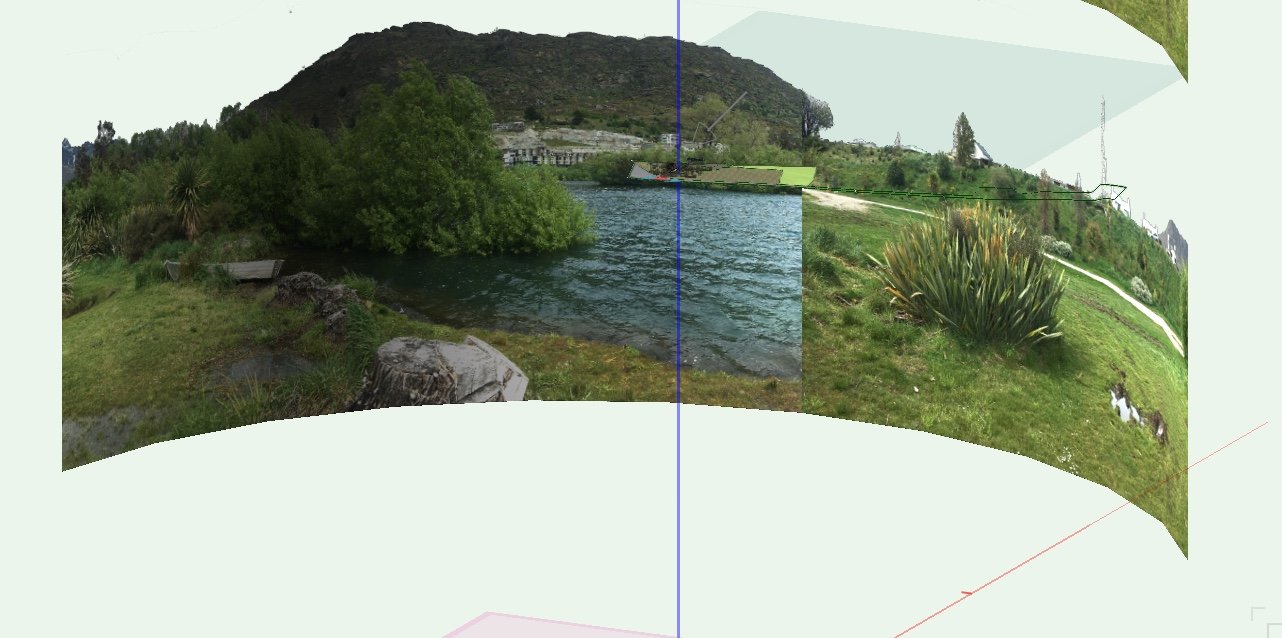
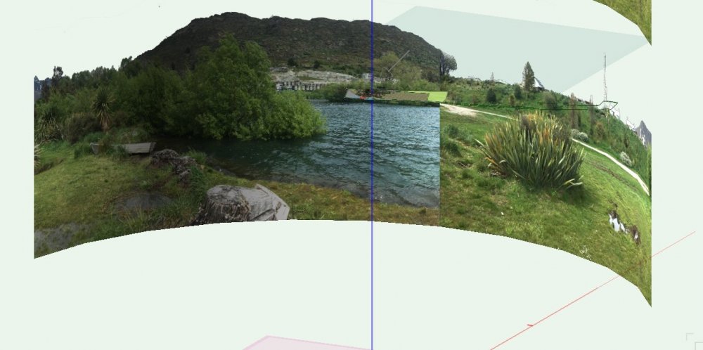
I am trying to place an outdoor panoramic background image around a model I am trying to render from 8 different camera angles. For the background I have made an image prop using an extruded arc that has been converted into a nurbs. On this I have placed a texture of the panoramic image, the sky has a transparency mask so I can use the HDRI sky in renderworks. The problem I am having is trying to get the image to scale and map to where I want it on the nurbs. for some reason the image crops out and repeats in random vertical sections and does not wrap continuously around the surface, I have tried using a decal but this has proved too difficult. I have tried turning off horizontal and vertical tiling and this doesn't work either. I'm sure there has to be a way to get this to work, any ideas much appreciated.
-
Railing Fence Tool - Corner Posts
Steve Riddle replied to ericjhberg's question in Wishlist - Feature and Content Requests
I'm using the fence tool and having the same issue with the corner posts rotating to 45 degrees. Also within the frame/panel attributes, frame bars don't appear to work independently from each other. I wanted to have horizontal slats at 10mm spacing and vertical slats at 200mm spacing for structure. The ability to add gates (in the same way as adding doors to walls) would be really useful. -
Am still having this problem, the text along path tool will not fill when setting the attributes to solid fill.
-
Area calculations of objects within Symbols
Steve Riddle replied to Steve Riddle's topic in General Discussion
This Great Thanks, I will place existing and proposed villa designs in a seperate layer and go through the steps above. Cheers, Steve -
Area calculations of objects within Symbols
Steve Riddle replied to Steve Riddle's topic in General Discussion
Hi Pat, Did you have any luck with this? It would be great if there was a solution as I have 27 villas (symbols) I need to provide cost orders for variations. Thanks Steve. -
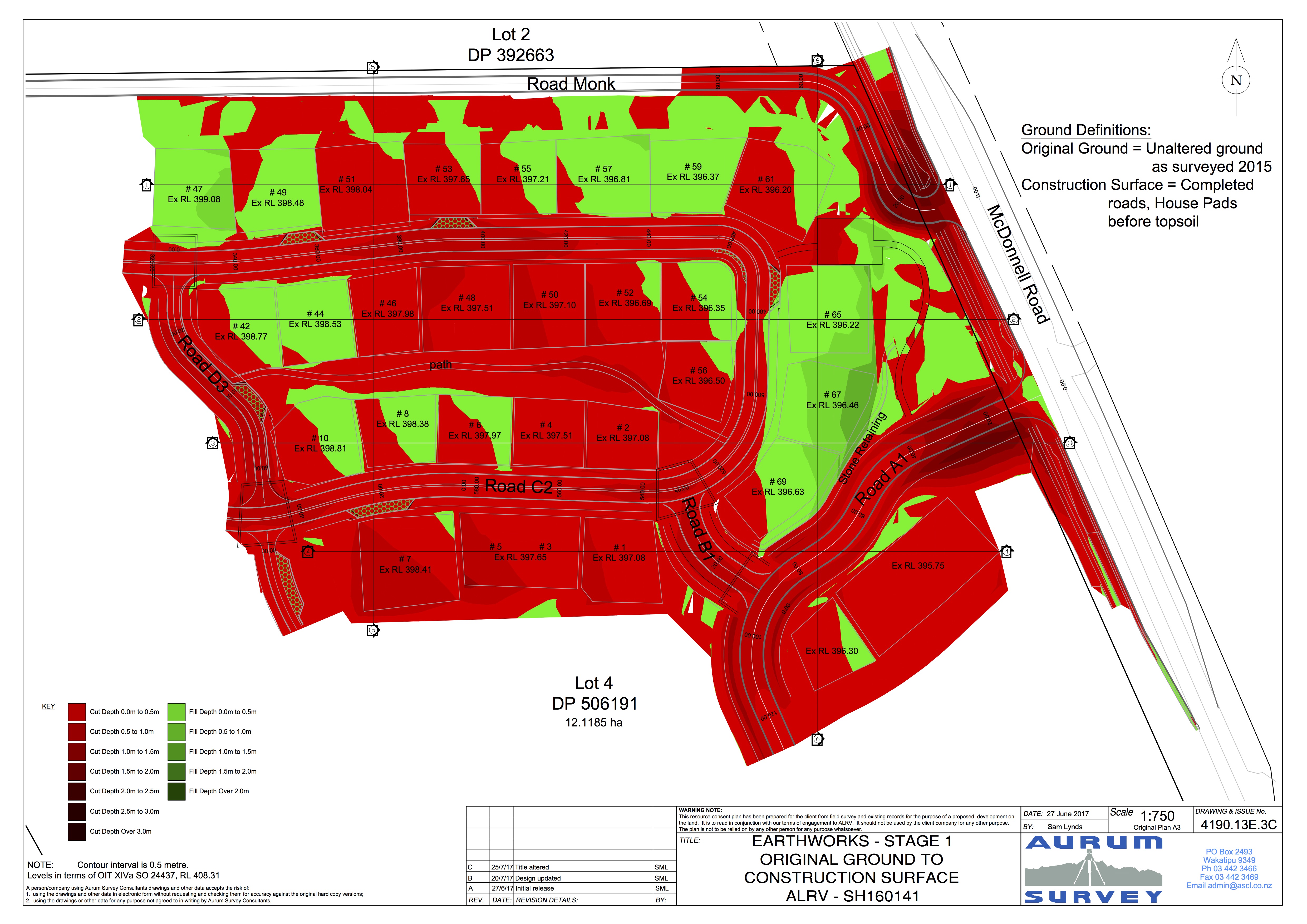
Display of Site Model cut/fill depth
Steve Riddle posted a question in Wishlist - Feature and Content Requests
I would like to see the ability to display Cut and Fill depth contours for earthworks plans, where the software calculates the difference between the existing and proposed site models. I often submit Earthworks drawings in Planning Applications that can show the extents of Earthworks and Cut/fill and proposed levels shown using the stake tool set to site model The council often requests further information with these as they want to know the depths, especially the maximum cut, I can currently only present these as cross sections, It would be great to be able to send a plan with coloured depth contours. -
I would like to see slab drainage features for hardscapes, with the ability to create channels, sumps and provide multiple falls. It would be good to be able to set the Levels of the top edge and bottom edge of the hardscape and have the software design and calculate the grades and directions of fall. Also to have the ability to set the level of and extents of an edge with fixed grades. I have a job where I am currently using multiple pad modifiers with landscape areas below to show extents and drainage of large paving areas in a retirement village. It would be great if I could use the hardscape tool for this.
-
Improved Landscape area updating
Steve Riddle posted a question in Wishlist - Feature and Content Requests
I would like to see improved landscape areas that can have specific plant mix for multiple areas changed via worksheet or dialog without requiring the eyedropper tool to update them all. I often prepare planting plans that contain a lot of Landscape areas but only a handful of plant mixes (eg. wetland mix, low planting mix, screening mix) It would be really useful to be able to save these mixes and have the ability to make adjustments to these mixes after the plan has been created. Using the eye dropper tool is not the best way to make these changes as there is usually a lot tags on the plan, and there is not an option to lock their position.(perhaps this can also be an addition to plugin parameters when using eyedropper tool). Currently about 50% of my time when preparing and revising planting plans is moving tags, I only want to place them once. -
Thanks Hans, I will have a look at the space tool.
-
Is there a way of displaying the areas of polygons with the text in the centre of the object without using the landscape area tool?
-
Area calculations of objects within Symbols
Steve Riddle replied to Steve Riddle's topic in General Discussion
OK thanks, see attached a copy of the file I'm working on, you will see on layer 'Floor Plans' there are villas that are embedded within symbols, as the villas sell the clients can request changes to the design. We are then required to prepare a rough order of costs for the changes to the landscaping that we pass onto the client for approval, this is where the worksheet comes in. I hope this makes sense. Thanks, Steve 265-4E.vwx -
I am working on a project that requires me to extract areas from polygons and landscape areas that are embedded within symbols and display them on a worksheet. I then need to summarise the areas by symbol name and class, Is there a way to easily do this as function within a worksheet or perhaps using marionette?
-
It would be good to have the ability to nominate the number of revisions displaying on the sheet border/title block. We use a small title block to increase the space available on the plan form and really only need to allow room for the 5 most recent revisions/ issues of the file. Is there a way to customise the issue manager so it displays a predetermined number of revisions ( ie allowing earlier revisions to drop off the sheet as a new set is issued?)
-
Live updating for site model section tool
Steve Riddle posted a question in Wishlist - Feature and Content Requests
It would be good to have site model sections that automatically update with the model, and the annotated levels. -
Drape Aerial photo
Steve Riddle replied to Steve Riddle's question in Wishlist - Feature and Content Requests
Thanks, I have tried the texture method but cannot find a way to map the georeferenced coordinates of the photo to the site model surface. Is there a way to do do this? -
Drape Aerial photo
Steve Riddle replied to Steve Riddle's question in Wishlist - Feature and Content Requests
Hi Jim, thanks for quick reply. I am trying to map it accurately (using a geotag) to a site model created from an imported GIS .shp file. The tiled aerial photos are also from the same GIS. we use them for Mapping large properties of 10-100,000 hectares and occasionally smaller properties. The aerial imagery aligns perfectly in 2d with the vector .shp data from the same coordinate system but taking this to 3d terrain is where i'm having problems. It seems there is some ability in vectorworks to create an image map or texture from the aerial photo. I may be overlooking something, but but am unsure how to scale, rotate and set coordinates for the image so it accurately maps to the corresponding site model surface. The ability to accurately drape any kind of raster image (not just aerial photos) to a site model would be a useful tool for our workflows. (Another good feature to have with regard to this process would be the ability to import more than one image at a time, often these GIS file downloads include 20 or so tiles of aerial imagery). Thanks, Steve -
Ability to drape a georeferenced aerial photo or tiled photos onto a site model surface.
- 10 replies
-
- 2
-

-
- site modelling
- gis
- (and 2 more)
-
Ability to display the depth of cut and fill in plan view Software to calculate the difference between existing and proposed site models and create colored contours, This is often requested by local government for earthworks consent plans, I can almost do the work myself but without this feature I have to refer to a civil design company using AutoCAD or similar.

-
Hi I am having the same trouble also, have imported 3d contour shapefiles and geotiff for a 1000 ha property my client want to run a visual simulation on for council. Have converted the contours to a site model and want to 'drape' the geotiff over the surface of the model using the existing scale and coordinates, perhaps I'm wrong but there doesn't seem to be a way to do this besides converting the aerial to a texture and placing a texture bed with the image on the surface of the terrain. This process throws out the scale and coordinate mapping of the aerial making it time consuming and inaccurate. Is there an easier way?
-
Thanks, I'll try it out!