


Urbanist
-
Posts
61 -
Joined
-
Last visited
Content Type
Profiles
Forums
Events
Articles
Marionette
Store
Posts posted by Urbanist
-
-
39 minutes ago, Art V said:
So for such a situation the option to automatically add a specified record to new objects would be quite useful as I would not have to do that afterwards through the OIP object. It would even be better if there would also be a fill-out dialog box as you can have with symbols upon inserting as an additional option to be set on/off.
A valid point indeed! A script that would attach records to objects without it and meeting some criterion (eg. layer) should be very easy to write.
Possible concept. 1. User selects an object with the record attached. 2. The menu command (script) creates a list of objects on the layer of the selected object, but without the record attached. 3. The record is attached to each object on the list, possibly with a date stamp.
Maybe 30 lines of VectorScript. Roughly 1 or 2 hours of work by a novice scripter.
A simple dialog for entering a single shared piece of data (eg creator) to all processed objects, typed by the user. Additional 3 or 4 lines of code in 5 minutes.
A fancy "modern" dialog for entering possibly required other data, with predefined drop-downs, but still without flashing lights and small fanfares at least until VW 2019. Maybe 300 lines of VectorScript. Roughly 20 hours of work by an expert scripter. Drop-downs that learn like those in FileMaker Pro: not the slightest idea even of the doability and elegant to use they would not likely be. (A short technical explanation may be needed: in FMP, a drop-down value list can be defined so that in addition to items given by the programmer, a user can type another value and that then is available in all records. it is not magic, it is the index of the field in question. No such thing in VW.
-
What are structural units? In the metric world there are only metric units, in the construction industry usually millimetres, but some countries e.g. Germany obviously centimetres are used.
-
14 minutes ago, Urbanist said:
The what to what -thing is not necessarily simple. I once tried to create a universal QS database and as far as the entity type was a sufficient way to determine th whats, I only needed to check whether the object being is processed is a bird or a plane. Certain other implicit items of data (file, layer, class, symbol name) were easy, but after wasting heaps of time (and not being a quantity surveyor) I gave up.
Just a few minutes later, in sudden moment of clarity, I remembered why I gave up. I went through a few decades of projects and realised that to get what I wanted would have required a huge number of wall types that would incorporate the painting system on each side and the facility to query those. My architectural English is even more lacking than my basic English, so forgive me for the long explanation. With painting system I refer to the entire surface treatment from structural wall to finish. Eg. in painted brick or blockwork walls there can be quite a lot of variation within a project. Eg. in a hospital or similar the corridor sides have simpler surfacing than in operating room sides. Once upon I time I embarrassed myself seriously by having an inadequate base for a hospital-grade painting. The client, fortunately, was forgiving although strictly speaking I could have been required to pay for the variation.
To quantify all this to a useful level for cost estimates just got too complicated, not to even mention the requirements to the VW user.
-
Databasewise a universal record is desirable so that the collected data can be efficiently processed in a separate database application with a reasonably simple schema. (Database in my world always refers to a real, relational database, not Excel.)
The what to what -thing is not necessarily simple. I once tried to create a universal QS database and as far as the entity type was a sufficient way to determine th whats, I only needed to check whether the object being is processed is a bird or a plane. Certain other implicit items of data (file, layer, class, symbol name) were easy, but after wasting heaps of time (and not being a quantity surveyor) I gave up.
-
10 minutes ago, michaelk said:
Famous last words: That should be easy to script
 .
.
Maybe, if one does not consider the requirement "what record to attach to what":
Anyway, I don't think that the available scripting languages can monitor the document and act when a new object is created. Maybe a C++ program done with the SDK could, but I would not call that scripting.
A script that would retroactively process all objects is technically simple to do, but the "what to what" clause is likely to complicate things quite a lot.
-
7 hours ago, emilie said:
Hi,
I'm really struggling to understand the hatch editor
We all are!
Years ago there was a 3rd party utility (Motivo?) that created hatches from patterns drawn normally. Obviously no-one wanted to pay for the functionality, so it disappeared. The user community can only blame itself for the lack of essential tools as there is no willingness to pay for anything; thus being at the mercy of Mr. Vectorworks, who does not do any real work with his software.
Another sad story is the demise of the Marketplace of Vectordepot. Really good stuff for $10-$20 per item, but few buyers.
-
 1
1
-
-
22 hours ago, Urbanist said:
Picture frames should be reasonably easy with VectorScript because they are planar and generally rectangular
I guess I tried to shoot before loading and aiming.
I can’t comment the Marionette proposal; being a puppet master was never a career option so I’ve not even tried it, but if Marionette has built-in functions (nodes?) for selecting symbols and maybe even textures, it might be a good choice. Assuming it does not ever require entering the dark worlds of VectorScript (VS) or Python, where angels fear to tread.
If it is for a mere mortal possible to enable selecing a frame profile symbol and even an image (texture or maybe image prop) in a Marionette object’s Object Info, go for it! In VS even one means easily hundreds of hours of frustration and despair with the arcane syntax and inadequate documentation ; whether Python is easier, I can’t comment. From some examples I have seen here, I’ve gathered that in Python one uses VectorScript function calls. The fourth option is C++, but even with the SDK (software development kit) one relies on libraries defined by Mr. Vectoworks. In VS perfectly working functions are being all the time removed with little advance warning, rendering your Plug-ins useless. As they sing, ”Wise men say, only fools VectorScript.”
In case of VS at least, the first thing to consider is the main user interface and the desired working mode. Whether you wish to hang your Pictures at the Exhibition as points, lines or polygons. Point and line can be hung in the plan view. This is what you need to decide when you say Create a plug-in object (or whatever the phrasing.)
From what you wrote one can assume that your pictures are rectangles and defined by overall frame dimensions. So, a Point object seems to be quite appropriate. In plan that can be shown as a line or be more complex, if required. It is possible to have interactive control points to define the width graphically.
A Line object would by default interactive as comes to frame width. 2D polygon is not a relevant choice and 3D polygon is (at least was) so problematic that I can’t recommend it, but theoretically it would allow you to draw any shape in a 3D-view, but this would always be interactive, you could not just give dimensions as you do with a Point or Line, which are fundamentally Plan view objects.
You need to define how your PIO interacts with walls in the same way as you do with symbols.
-
On 9/27/2017 at 3:48 PM, NCSMITH said:
However, what I would like to know is: is it then possible to make this profile/path object parametric so that we can copy/paste it for different size pictures and then input the size frame we need? To make a new path for every picture would be very time consuming!
")
Picture frames should be reasonably easy with VectorScript because they are planar and generally rectangular; non-planar objects are useless as the profile twists and turns. However, choosing the profile is the main issue. Plain rectangles are easy, but using custom profiles stored as symbols may not be. If you are happy to type the profile symbol name, fine, but if instead you want to have a dialog to choose one , you are in trouble. In my scripts for such purposes the script goes to the symbol definition and tries to find an object in the specified class (called, surprisingly, profile) and uses that.
-
17 hours ago, Art V said:
Depending on the amount of data you could consider using the built-in spreadsheet.
Well, in one MapInfo project even FMP of the day (ca 2000) was unable to handle the number of transaction records we received (millions), but fortunately I was able to preprocess them with FoxPro to form relevant summaries (reducing the data amount to only tens of thousands of records.) Linking data to VW objects would have been totally impossible, we had thousands of polygon representing the postal code areas that were the interest. I have the feeling that even MapInfo would have died trying to process the original data.
-
1 hour ago, Art V said:
This is not going to be a short and simple answer, as it depends on what you want/need.
An excellent introduction to the issues at hand, thank you!
I have in fact once bought a Windows (95) machine to run AutoCAD LT, for QA reasons. A typical situation was that an ACAD user sent a file that could not be openened in VW or was unusable. In almost all cases, the fIle was just as bad in AutoCAD.
A few of years ago I again bought a cheap Windows laptop, this time to check our IFC files with Tekla Model Viewer, as Solibri's free IFC program that worked on the Mac caused various problems and the local undustry standard was shifting towards Tekla.
I've not tried to use VW's GIS-functionality (no such projects lately), but in the 1990s when MapInfo was still available for the Mac, I used it for certain demographic studies related to urban planning. Anyway, in my thinking GIS runs as mapping engine or alternative front end to large alphanumeric databases and I've not been able to efficiently and usefully link FileMaker Pro data to VW via ODBC.
-
17 hours ago, Rossford said:
VW does have a CF analysis, with shaders similar to slope,
It does?
Well, there we go: I haven't used the DTM in detailed design for years, probably not since VW 9 or 10, so I guess I don't qualify as a real practitioner. If this functionality existed in those distant years, I have completely missed it.
I'll put my VectorScript pencil back to the pen box, then. Fortunately I did not waste time sharpening it.
Thanks!
-
The contact facility of VectorDepot does no seem to work and I'd need to contact Patrick. Does anyone know his email address? No particular hurry.
-
Not that I, as a retiree, would have much use for this, but out of curiousity: how many real landscape designers doing real work ("industry experts" at VW offices obviously do not qualify) would want to be able to determine the fill depth at a location, or for that matter, cut? That is: the level difference between existing and proposed terrain. The issue that got me thinking about this is a near-by building site, where the root areas of existing trees are liberally filled. We used to stipulate in our specifications the maximum fill in such situations, but of course had no feasible way to determine whether that was possible, especially in the old manual drafting days, grading plans coming from engineers, who would not give a hoot.
The functionality may be somewhere in Landmark (I've not used it much in the last years and not to do real work), but if not, it might be possible to write a VectorScript tool or PIO for the purpose, perhaps even so that the PIO would double-shift as a proposed terrain modifier.
Ideally, there would be a built-in option to graphically illustrate the cut & fill depths in the same manner as one does slope analyses. With an automatic legend this time.
-
The unfortunate and wrong contour generation at concave parts of the site is an integral part of the Terrain Modeling engine of VW; it might even be called a feature. The larger and more complex the site, the more errors.
-
1 hour ago, lisag said:
Is it possible to generate a set height contour for a proposed model?
For example, I have built a proposed site model. I don't know the footprint of the lake on the on my model in plan, but I do I know the water level on site is 29.150.
So, if I could generate a poly line at this height around the model, i.e. a contour line, I would be able to see the footprint of what will essentially be the lake and calculate area / volume etc?
A very good question! Too lazy & tired to test and no useful data set to use, but have you tried site components such as Pad, at least for illustrative`purposes? Water volume would be quite interesting in ecological landscape design, but of course one would need lake bottom data.
-
12 hours ago, Art V said:
I know what you mean with Mac vs PC and AutoCAD vs VW. It is that VW cannot meet certain client requirements for specific dwg based documents (mostly text styles , fonts and a few other things) or I would completely drop AutoCAD.
Tell me about this! The probably largest buyer of landscape consulting services in my country (the public works department of the capital city) has explicitly forbidden the use of VW a long time ago and later mandated (in my opinion illegally, considering the competition legislation) that all work must be carried out using Microstation. I can even imagine officials, wearing Fedoras, carrying out razzias to reveal the use of other software in violation with the contract.
The VW ban appears to be have been caused by uninformed users and the silly "define origin" function (at worst invoked my the even sillier rulers), resulting in a situation where the consultant's files cannot be incorporated in the municipality-wide CAD-database as the proposed new playground is located thousands of kilometres away.
-
23 hours ago, FBernardo said:
Hi all,
The compatibility and possibility to use other software besides vectorworks in our office (the answer i got from my colleagues and the fact they don't like MacOS)
Well, one can have Windows installed on a Mac and run it either separately (rebooted) or simultaneously (needs tons of RAM).
In my experience there are few people who wish to move from the Mac to Windows, even former Windows users generally prefer the Mac. I've dealt with an AutoCAD power user, who after some monhs of pondering, switched to VW and Mac as his colleagues in the office he was hired to be the AutoCAD man, were so much faster and less frustrated, producing superior drawings without sweat. Discipline was landscape architecture, large scale.
However, the current Mac line is obviously somewhat problematic as comes to VW's requirements.
-
On 9/20/2017 at 0:30 PM, lisag said:
I'm glad it's not just me, though am frustrated and disappointed that there's not an easy fix for this? We had assumed using landmark for topographic modelling would be straightforward.......

Unfortunately terrain modeling is anything but straightforward. As someone from the old school I like to think new landforms with contours. Luckily I do a bit of programming and was able to create a semi-satisfactory contour tool. It of course does ot help with the problems of the DTM engine itself. All these pads and what have you may be fine for architects who deal with small houses on topographically simple sites, but they are next to useless in landscape architecture. Not sure about garden design, never done that.
-
12 minutes ago, Christiaan said:
Bricks are 215 x 112.5, so dimension would actually be 327.5
Lucky you: the dimensions are easy. In my time I had to deal with 270 x 130 which caused interesting overall dimensions. Later they developed a new size 285 x 85, which gave a 100 mm grid, when laid as 1/3 but the result was horribly ugly.
I guess would lay virtual bricks but nevertheless do my calculations. Also, in my short time on the building site the supervisor liked to save on mortar so should there have been piers like that, they might have been smaller than designed. To be honest, I liked saving mortar, too, because receiving the mortar container to the platform was really scary; a 300 kilogram payload of mortar swinging towards you several times a day was not fun.
-
What is the brick size? One of the first real jobs I did as a young student was to dimension a brick facade. It was sort of fun because a couple of years earlier I had worked on a building site as a brickies' brick & mortar boy and spent a lot of time selecting bricks of suitable size as a foundation pour had not gone exactly right and six storeys worth of both oversized and undersized bricks were needed. The bricklaying work was done from hanging platforms that had to be manually lifted by means of winch levers in 5 or 6 frames. One of my duties was to receive loads of bricks and mortar, lifted by a crane with no direct sight to most locations, yelling instructions to the crane operator via a walkie-talkie from between the incoming load and building wall. Probably an illegal situation, but in 1972 no-one cared too much about occupational safety.
-
1
-
-
10 hours ago, Christiaan said:
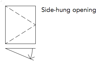
It's quite relevant in this elevation
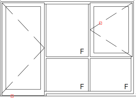
Fair enough, but no window manufacturer I have ever worked with needed such a representation. A diagram with single lines, dimensions and references to details or standards was enough. But as I said, industry practices vary and my main experience is from manual drafting in the 1970s and buildings with hundreds of windows usually following a typology. I have no idea of a workflow in which submodels such as your example can be reliably extracted from the building model, where one of course determines the dimensions and swings, but no-one wants such ugly lines in the elevation drawings. And speaking of details: I and my colleagues worked often very hard to find suitable steel profiles from manufacturers' catalogues, only to learn that the ones we chose could not be used for one reason or another.
10 hours ago, Christiaan said:Totally irrelevant to most of the window manufacturers we work with
-
5 hours ago, Christiaan said:
A key/legend solves that problem.
Keys and legends are a sign of poor drafting.
5 hours ago, Christiaan said:Forcing people to look at plans to know the swing of a door is lazy drafting, especially when you have a 3D model as a single source of data. It's not just door schedules either. Window schedules have doors in them.
One of the first things I learned was not to draw anything that does not have relevant information value or is shown elsewhere in a more appropriate or detailed way. The swing of a door in an elevation is irrelevant, especially when we have a 3D-model that can show doors opened or shut. That is how one communicates to non-professional clients in this century. In my country, the door schedule is the legally binding document in this respect. No matter what you have in plans or elevations, industriously drafted, the doors that are delivered are those in the schedule.
-
On 9/19/2017 at 1:46 AM, JHAM said:
Just downloaded 2018 and I am migrating over..
Tell me if I am missing something, but I cannot get the Door Hinge Markers to show up as dashed line type in an elevation (hidden line render).
I'm certainly missing something since I don't understand the need for this. A non-professional client does not understand the obscure and funny hinge marker anyway and surely the professionals use door schedules in combination with floor plans. Industry practices of course vary.
-
The DTM engine has had quite a few quirks with valleys ans swales, the algorithm does not look ahead, but connects closest points in a non-topographic way. I've had a few terrains that VW simply failed to model correctly. The most disappointing one was about partial filling and landscaping a former open-pit mine which would have been a quite significant project, especially fee-wise and also because there might have been several similar ones. I even considered getting AutoCAD, but with no required skills or machinery, just had to give up and decline to tender. Thank you, Mr. Vectorworks!
Generate Scope Drawings from Wall Styles
in Architecture
Posted
Good question, a useful approach for certain purposes. I remember a project long time ago (manual drafting days) where the client's cost consultant complained about the cost of a particular wall type. Surely it was expensive, but there was perhaps 100 sqm of it in a large project and it did not require a separate contractor or anything like that.
Fortunately I knew the project by heart to the smallest detail so was able to quickly quantify the problem and show it in proportion with a red Textmark. End of discussion.
I take you have tried using classes and viewport class overrides?