


reGenerate Design
-
Posts
37 -
Joined
-
Last visited
Content Type
Profiles
Forums
Events
Articles
Marionette
Store
Everything posted by reGenerate Design
-
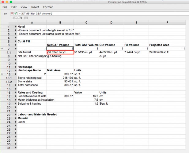
Hi Boh, I'm working on a similar application but I don't quite know how to make my worksheet recognize cut and fill values as numbers and not strings (as it seems it cannot use strings for making calculations. I see in your worksheet above that your cut and fill values are adding up in a totals row. I have used the "Create Report" option in Tools to generate a database row that shows only site models and provides some field information about the site model (row 7 in my worksheet below). When I try to do calculations on these site model values, I get unexpected results. How are you pulling your cut and fill values in your worksheet? Thanks so much , Adrian
-
Hi Pat, for sure. Here it is attached and I've added in the dimensions that they should be. Hopefully I'm not overlooking something simple here. My motivation for this is generally to create various parts for a project and use VW to track their sizes on the worksheet, such as a lumber cutlist for a woodworking project. Thanks again for looking it over. test.vwx
-
Thanks a lot for your response Pat. I think the main area where I'm having trouble is that when I use Width or Length or Height in a worksheet formula, it seems to give me different and unexpected values returned depending on the orientation the object or symbol is in the design layer. I'm hoping I'm able to use a formula that can return the actual dimension of an object or preferably a symbol regardless of what view is used, such as Plan, Top, Isometric etc. Actually in my document I'm getting rather unpredictable results with length and width. Grateful for any further thoughts on this!
-
Hello, I'm still a bit of a newbie to VW, but does anyone know how to use a worksheet column to report what the dimensions of a symbol or object are, regardless of how it is displayed or oriented in a design layer? I am simply using extruded shapes converted into symbols to represent various pieces of lumber for a project and would like to use a worksheet to function as a parts list where the various lengths of lumber types are reported by the worksheet based on the drawn dimensions of each symbol. I played around with the IF statement to only print the longest dimension, but it seems that the orientation still plays into what is reported. The project is attached. Any help would be hugely appreciated! Rock display table.vwx
-
Hello, I'm hoping someone can guide me in the right direction: I'm a VW 2015 user and I've having trouble finding out how to colour a texture bed modifier that is created by the Hardscape tool. Everything is working properly except the colour of the texture bed that is draped onto my DTM (right now it just appears as white, which is the same colour as my "none" class). Where I've gone into my Hardscape Settings with the hardscape selected, and I've set the 3D type to Texture Bed Modifier. Below that is a drop don menu labelled "Main Texture" where I should be able to set how the texture bed is coloured, but I only have 2 relevant choices: "None" and "By Class". Strangely, when I choose "By Class" and hit ok and then go back into the Hardscape Settings, it does not remember my choice and is set back to "None". Even if I was able to choose "By Class", where do I tell it what class to use? Grateful for any pointer you may have on this. I've attached the file I've bee playing around with. Adrian Record practice.vwx
-
Hello everyone, I'm hoping someone can help me with the following: Is there a way to set all selected plants within a Vectorworks document to a particular project ID in the VW Plant Database? I would like to be able to provide clients with a found set of plants in the VW Plant database that is based on the plant symbols in the VW program. One inquiry I have toward achieving this is if there was a way to append a Project ID to all plants in the VW Plant Database based on which plant symbols are in a project in VW program. I have version 2015 but if this is not possible in that version, I'm curious if this is possible in version 2018. Thanks!
-
Hello there, I'm hoping someone is able to help me figure out with making legends in VW 2015. As I'm a VW novice, I was happy to discover using Worksheets to make legends automatically as previous to discovering this, I was hand-building legends which are time consuming to manage. However, where it comes to lines (such as property lines, contour lines, utility lines etc.) I'm having trouble figuring out how to have VW just display a straight horizontal line as a legend item that's easy to see (like you would see on professionally drafted plans). I've attached a sample file that contains a worksheet that serves as a legend. The legend is on the left of the drawing on Sheet 01 Finalized Concept Design. Does anyone have any advice on how to make the line legend elements appear as simply straight horizontal lines (as opposed to the random lines that are generated by VW)? Thanks so much in advance Local_Roth_Design.vwx
-
Hi there, I'm learning about site modelling in Vectorworks and I have question about site modifiers. I'm trying to model a site that has an existing retaining wall. As I'm quite new to VW and maybe this is the incorrect approach but, I went ahead and made a Wall object with the appropriate elevations and then used the "Create Retaining Wall Site Modifier" to modify the terrain on either side of this wall. This 'existing' retaining wall passes through an area where I want to modify the proposed site model that is within a Grade Limit boundary. This is where I found out that you cannot overlap two site modifiers over each other without getting errors and unintended modelling results. My question therefore is when modelling an existing site, how do I model an existing retaining wall or similar other structural feature - that runs through an area where I'll be making proposed site modifications - in such a way that does not require the retaining wall involving a Site Modifier? This will allow me to avoid having two site overlapping site modifiers. I've attached a quick site model I made where I placed in a wall into the area where I'm making proposed site model changes resulting in the errors. Hopefully this question makes sense! Thanks everyone for your thoughts! 2018-02-21_Site_Modelling.vwx
-
Hi Zoomer thanks so much for getting back to me. Textures are already enabled in the OpenGL options (the 'use textures' box is greyed out but with it enabled.
-
Hello there, I am hoping that someone might be able to help me with a Vectorworks 2015 3D rendering issue that I'm experiencing. When I try to view plant objects in 3D, I only see a grey box in the openGL 3D preview pane. I've attached a file that has a single plant object in it. I would expect that I should see the 3D graphic or image prop for this plant object instead of a grey box. I have set the render mode to be openGL in VW preferences already. Thanks so much for any help on this. Adrian VW 2015 3D plant object issue.vwx
-
Hello bc, thanks so much for your input. That made everything work! Quite new to VW and exploring the world of site modelling and so this really moved me forward. Thanks a lot!
-
Hello everyone, I'm hoping someone can help me understand an issue I'm facing when I make a section viewport through a retaining wall I've made in a site model. When I render the viewport, not only am I seeing some bold lines that outline the correct surfaces in my section view, but I'm also seeing some unexpected bold lines for geometry that is not in the model. I've attached the Vectorworks 2015 file to this message. Thanks so much and grateful for any thoughts on this matter! Adrian test_model.vwx

