mike m oz
-
Posts
4,876 -
Joined
-
Last visited
Content Type
Profiles
Forums
Events
Articles
Marionette
Store
Everything posted by mike m oz
-
Automatically creating Loci in 2016 Fundamentals?
mike m oz replied to GrahamT's topic in General Discussion
If you have your Snaps set correctly on the Snaps palette there is no need for loci because the points you mention will already be available when you use the Move (and copy) by Points tool. -
It only works on Roof Face objects. So you would need to ungroup your Roof object to get access to the Roof Face objects. An easier way though is to reshape your larger Roof object with the Reshape tool to give you the configuration you want.
-
Use the Connect/Combine tool on the Basic tool palette. Click on face of first roof and then drag to face of second roof.
-
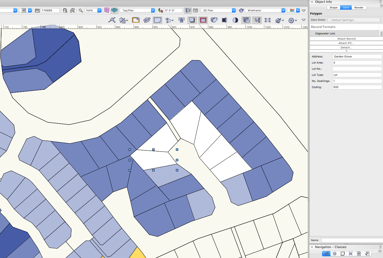
Data Visualization now works on Design Layers in Vw 2020. On Design Layers it gives you live updating as you change the Record of an object. Sheet Layer Viewports are used to provide views of the Data for printing. The image below shows the Data Visualization being used to graphically show the size of lots.

-
You need to edit the Rustic Shutter symbol in your file and change the Class of its 3D components to the Class created for the rustic shutters.
- 16 replies
-
- 1
-

-
- window tool
- color
- (and 1 more)
-
Edit the 3D component of the Rustic Shutter symbol and change its Class from None to the Class you have created for the shutter. Window with Rustic Shutters..vwx
- 16 replies
-
- 1
-
-
- window tool
- color
- (and 1 more)
-
If you want different textures for different components of the Window object you need to define the Texture as part of the Class for each Component and then on the OIP set the Texture to Class Texture. I know that seems a little obtuse but that is the way Vectorworks does it.
-
Are the existing windows Vectorworks Window objects or are they Symbols? If they are Vectorworks Window objects use the command Update Plug-in objects in the Utilities sub menu menu in the Tools menu. If they are Symbols edit the Symbol to see if they are Vectorworks Window objects. If they are then update them. If they are Symbols that are not Vectorworks Window objects then you should be able to Class the individual 3D component parts. Also check to see if the shutters have been modelled separately.
- 16 replies
-
- 1
-
-
- window tool
- color
- (and 1 more)
-
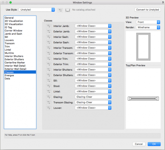
You control the appearance of the different components of the Window object by Classes. Create a unique Class for the external or internal shutters, choose the colour you want (or the texture you want) and set the Class properties to Use at creation. Then assign that Class to the external or internal shutters in the Window Settings dialog box.
-
VWX 2020 - Bug - Saving dimension settings
mike m oz replied to Andrew Davies's question in Troubleshooting
Tamsin, the weird unit expression is definitely a bug. The non appearance of the set units in a new file is not a bug though. Some users assume that units are a global preference. ie all they have to do is choose Imperial or metric. Unfortunately it isn't. -
VWX 2020 - Bug - Saving dimension settings
mike m oz replied to Andrew Davies's question in Troubleshooting
It is not a bug. It is working as designed (WAD). Dimensions are not a global preference. They are a file preference. When you set Dimension preferences you are only doing it for the active file. If you want those preferences to become a default for your work you can only do it by saving those settings as part of a Template file. To 'recall' them you then need to use that template file as the 'base' for the new file you are creating. Or you can create a unique 'Dimension Style' and then import that. Easier to incorporate it as part of your 'template file'. -
VWX 2020 - Bug - Saving dimension settings
mike m oz replied to Andrew Davies's question in Troubleshooting
I'd only worry about it if it persists. -
VWX 2020 - Bug - Saving dimension settings
mike m oz replied to Andrew Davies's question in Troubleshooting
After making the changes you want to set you need to save a Default Template file and then select that as the base for your new files when you create a new file. The Template file doesn't need to be named Default. It can be named anything of your choosing. The important thing is that you set it in the pop-up list when you create a new file so that it is the one that is used. -
Lee, I've never seen that issue. What OS, how much RAM does your computer have and what graphics card does your computer have? Also which version of Vectorworks and series?
-
You need to set your Layer visibility options to Show Others or Show Snap Others. Your two layers also need to be the same scale and both in Top/Plan View.
-
Vectorworks User Interface Overhaul
mike m oz replied to Thomas Wagensommerer's question in Wishlist - Feature and Content Requests
Zoomer, Texture seems to be a more common generic term in usage. I've always understood a shader to be a machine generated texture pattern and a texture map to be an image based texture pattern. Materials as a concept makes sense but only if you start talking about components of objects and defining their appearance in plan view, 3D views and sections in both linework views and rendered views. Also their properties in terms of energy analysis, weight, strength, etc. In Vw. Isn't that what we tend to do with Classes? Classes are the what in Vw with materials being one of the what classification systems. -
Vectorworks User Interface Overhaul
mike m oz replied to Thomas Wagensommerer's question in Wishlist - Feature and Content Requests
Top/Plan = PLAN -
The Classes you are using for your objects become Container Classes when there are objects that are complex and have different Classes used for their components. The None Class needs to be visible at all times and in all Viewports. Your visibility problem exists because you are trying to use the None Class to control visibility of objects or object parts.
-
The None Class is a default Class for objects and should never be made invisible, If you have objects that you want to have the ability to be seen or not seen then create a Class for them.
-
Do you have the Document Preference Save Viewport Cache on?
-
Line-weight, I didn't think through the problem before posting. Stephan is correct in that the number of sides needs to be even.
-
Fifteen is the correct number. There will need to be eight of one length and seven of the other length and you will need to nominate which of the two length there is eight of. You might be better off posting your query on a geometry/trigonometry maths query website.
-
If you are doing a building model workflow then all of your annotation for views generated from the building model, including plans, should be in Viewports on Sheet Layers. If you have 2D only drawings, such as details, on other Design Layers then you can choose between annotating on the design layer or in the annotation space of its Viewport on a Sheet Layer.
-
The Framing Member tool has the capability to use a custom profile.
-
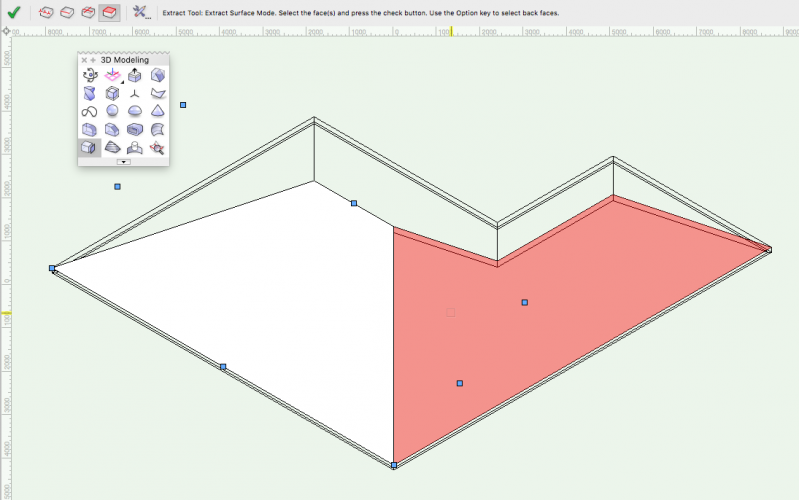
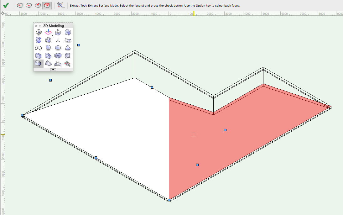
"unfold" roof to obtain actual roof size and run
mike m oz replied to O Design's topic in Solids Modeling
If you need the surfaces as graphic elements then use the Extract tool in extract surface mode. In too preferences set the mode to planar surface. Each surface can then be rotated in a side view by the roof pitch so it is parallel to the Ground plane.