mike m oz
-
Posts
4,876 -
Joined
-
Last visited
Content Type
Profiles
Forums
Events
Articles
Marionette
Store
Everything posted by mike m oz
-
Line-weight, the Chain Extrude command has always only worked on paths which have straight line segments. The paths also need to be parallel to the Ground Plane.
-
Model it how you think it would be built. If all the battens need to be the same size and shape try using Duplicate along Path in Fixed Distance mode.
-
VW US Windows (unequal bi-part tilt/turn configuration)
mike m oz replied to zoomer's topic in General Discussion
Possible that some users will want shims between butting units to replicate the real life scenario of adjusting units so they are vertical. Likely that would be the same width as the jamb to wall shims. Thus maybe separate shim thickness are needed for wall jambs and butting jambs. -
VW US Windows (unequal bi-part tilt/turn configuration)
mike m oz replied to zoomer's topic in General Discussion
Matt, One way around the problem would be to have user defined shim gaps for each edge. A better way would be for butting shim gaps to automatically set themselves to zero when units are butted up again each other. -
Section lines that can bend, not just step
mike m oz replied to Christiaan's question in Wishlist - Feature and Content Requests
Whilst the 'author' might understand what is going on with complex sections like those proposed, will the contractor, subcontractors and tradesmen understand it. The risk is them not understanding it and errors occurring on site. The resulting argy bargy about who is responsible and who is going to pay to fix the mistakes is territory best avoided. -
VW US Windows (unequal bi-part tilt/turn configuration)
mike m oz replied to zoomer's topic in General Discussion
Zoomer, you can do all of your first three with the custom configuration of the Window tool. The last one you can do with the Door and Window tools. The only issue appears to be the Wall break line that shows in Plan View when you have shim gaps. Set the shim gaps to zero and there is no Wall break line in Plan View. -
VW US Windows (unequal bi-part tilt/turn configuration)
mike m oz replied to zoomer's topic in General Discussion
Zoomer, can you please provide elevation views of what you need. -
Window tool: - Click on the Settings button and in the General Pane select Custom Configuration. - Edit the Custom Configuration to define your number of columns. - Define the window type for each cell. Windoor tool: - Click on the Form button. - Create two horizontal cells. - Select which casement type you want in each cell.
-
Windoor doesn't do curved windows.
-
If you want to taper to a single point use the menu command Tapered Extrude (Model menu) and enter the taper angle you want. If you want to taper to a single line top edge then draw a line where you want that to be, then select the line and rectangle and use the menu command Multiple Extrude (Model menu) and give it the height you want. There are other ways to do both, but these are the simplest way to do it.
-
It isn't just about showing the client the design. They need to be able to explore and understand what their project will be like. Thus we need to be able to give a client a 3D model of the building and the site that they can easily navigate around.
-
Game-like navigation through 3D models
mike m oz replied to Christiaan's question in Wishlist - Feature and Content Requests
It isn't just about showing the client the design. They need to be able to explore and understand what their project will be like. Thus we need to be able to give a client a 3D model of the building and the site that they can easily navigate around. -
Yes.
-
Game-like navigation through 3D models
mike m oz replied to Christiaan's question in Wishlist - Feature and Content Requests
The architecture paradigm is rapidly changing and those that don't start working in 3D will end up being marginalised. -
I have a client who is having difficulty with the PC Navigation. Advice on how to get them a better experience would be greatly appreciated.
-
VWX 2023 - DWG import - Blocks not coming in as symbols
mike m oz replied to Jeff Prince's question in Troubleshooting
Jeff, if you rule out everything obvious then please submit a bug report: https://www.vectorworks.net/support/bugsubmit -
VWX 2023 - DWG import - Blocks not coming in as symbols
mike m oz replied to Jeff Prince's question in Troubleshooting
Jeff, I would check that it isn't an exploded DWG. -
VWX 2023 - DWG import - Blocks not coming in as symbols
mike m oz replied to Jeff Prince's question in Troubleshooting
What version of Vw and which SP are you using? Also which OS? -
VWX 2023 - DWG import - Blocks not coming in as symbols
mike m oz replied to Jeff Prince's question in Troubleshooting
Click on the Advanced button in the bottom LH corner of the DXF/DWG Import Options dialog box and make sure the option to Convert all blocks to groups isn't check marked.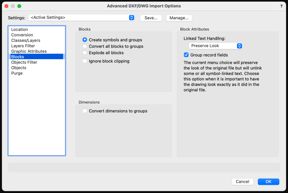
-
Outdoor Brick or Concrete pedestal for School Mascot (Ram)
mike m oz replied to The Hamma's topic in Site Design
A structural engineer will be able to give you appropriate advice on the three parts and connections between them. -
The underlying 3D geometry of a non planar 3D polygon with more than 3 vertices will be triangles as shown in this Artistic Renderworks image.

-
3D polygons are planar so need to have only three vertices. You need to either raise the 3D polygon ends in the centre of the image so they finish on the edge of the 3D polygon on the right or break the latter up into smaller triangles that join at the lower common point.
-
Outdoor Brick or Concrete pedestal for School Mascot (Ram)
mike m oz replied to The Hamma's topic in Site Design
Have you tried to find a suitable one at Sketchup Warehouse? If you find a suitable one you can import it into Vectorworks. Alternatively provide a sketch of what you want so it can be modelled. -
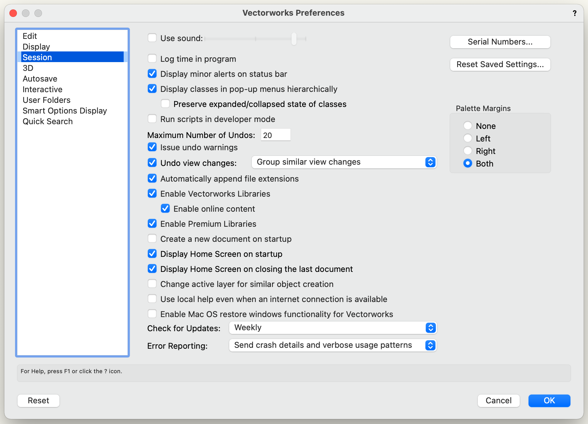
Vectorworks Preferences / Session tab. Uncheck: Display Home Screen on startup Display Home Screen on closing last document

-
2" Mid Reveal in Cabinet PIO Can't Be Changed
mike m oz replied to Sky's question in Troubleshooting
The Cabinet tools are scheduled to be improved. https://www.vectorworks.net/en-AU/public-roadmap All too often I end up modelling cabinetwork because the existing Cabinet PIO capabilities can't get me close enough to what I need.