
lisagravy
-
Posts
203 -
Joined
-
Last visited
Content Type
Profiles
Forums
Events
Articles
Marionette
Store
Everything posted by lisagravy
-
Thanks @RussU - much appreciated. Also thanks @Tamsin Slatter - I have tested exporting the georeferenced file to DWG and reimporting in a non-georeferenced file, and it doesn't maintain X, Y co-ordinates unfortunately. I think the reason is that if you geo-locate, and effectively move the user and internal origin to the project location, the export retains the X, Y position relative to this origin point. If you didn't geolocate it might retain the X, Y co-ordinates, but then we would obviously have issues with functionality of the file? The only way I can get it to work is by geo-locating, but then moving the user origin back to the equivalent of British Grid 0,0. Then the X, Y in the file looks to be representative of the E, N values... and exports and imports again ok. But I don't want to start doing this if there are issues with it I can't see... 🙈
-
@RussU It depends on the project really? The drawing I have open is just under 1km square. I need to be able to provide a contractor with co-ordinate points for that, usually set out to the nearest millimetre? (Some other drawings are obviously much smaller!) Edit: I typically work in Scotland, and British Grid origin is south west England so in terms of X, Y distance from user origin 0,0, this can be X: 300000m Y: 800000m, which would relate to British Grid Easting 300000, Northing 800000m, if that makes sense?
- 28 replies
-
- 1
-

-
- gis
- georeferencing
- (and 3 more)
-
Sorry to continue this @Tamsin Slatter, but actually the discussion on the X&Y / E&N discrepancy has actually raised another couple of points for us! My (albeit limited!) understanding of British National Grid is that the Eastings and Northings are projected flat and are equally spaced, which is how we used them before accurately just by referencing X and Y? I did a test where I imported a DWG file not geo-referenced, and checked an X Y position on a standard stake, and then imported a georeferenced version of the same file to check the Eastings and Northings of the same point on a GIS stake, and I get the same answer from X,Y to E,N. If X and Y will never completely match Easting and Northing when the co-ordinate system is active, how does this work in terms of us actually drawing information? For example, should we still be drawing accurately using the standard poly line / arc tools etc, and lengths and dimensions as we did before? Would you ever draw with Great Circle? Also - a lot of our 2020 files have an active geographic co-ordinate system turned on as default (before we really understood what this was)... we've been using these files as per our existing workflow, i.e. X & Y as British Grid, ignoring all the georeferencing settings. (Though to be fair the georeferencing tick box on all the layers is disabled.) Will this affect any of our dimensioning on these files?
-
Thanks @Tamsin Slatter ! I've had a quick play with the Great Circle tool and a read through of @RussU 's post, and I get what you mean! Can see a difference of around 7 or 8mm over the 50m section I've tested. I just wasn't sure if because British Grid is a projected grid system it would have worked locally or not.
-
Thanks @Tamsin Slatter - I guess.... (possibly incorrectly?!) that if I move the User Origin back to British Grid origin 0,0 after geolocating my file - by firstly defining it's current Easting and Northing position via GIS stake, and then moving it to the negative X and negative Y values of this - this sets my X and Y values to be the same as the eastings and northings? And then I could use the X Y positions of the GIS stake to move?
-
@bgoff Thanks @bgoff - I've already set my file to use OSGB 36 and the origin is set, the file is accurately positioned and georeferenced. My question is about whether or not I can position a GIS stake point by typing in the co-ordinate, or if point and click to position is the only method?
-
Is there a way to move a GIS stake to a defined co-ordinate position? For example, with a normal stake, you can place a stake, and then amend the X, Y details to move it to an accurate position. Can you do the same with a GIS stake, to identify a particular co-ordinate position, i.e. 257850E, 667750N (British Grid) - without having a line or point on the drawing already in this position to snap to?
- 28 replies
-
- 1
-
-
- gis
- georeferencing
- (and 3 more)
-

Vectorworks Upgrades
lisagravy replied to lisagravy's question in Wishlist - Feature and Content Requests
@Tamsin Slatter Amazing! Thank you. No idea this existed! -
When we have a Vectorworks upgrade, would it be possible to include a batch upgrade of external references feature please? I love having 2020, but for every existing file I open, I have to individually go and overwrite all my external references in the new version before the file works properly again - I had to do this with 2019 too and it took a fair bit of time. Not an issue on smaller jobs, but a 'would you like to update all your external references to the new version' feature, or a batch way to do this, would be really really beneficial on more complex projects which are at Christopher Nolan 'Inception' level of external referencing?
-
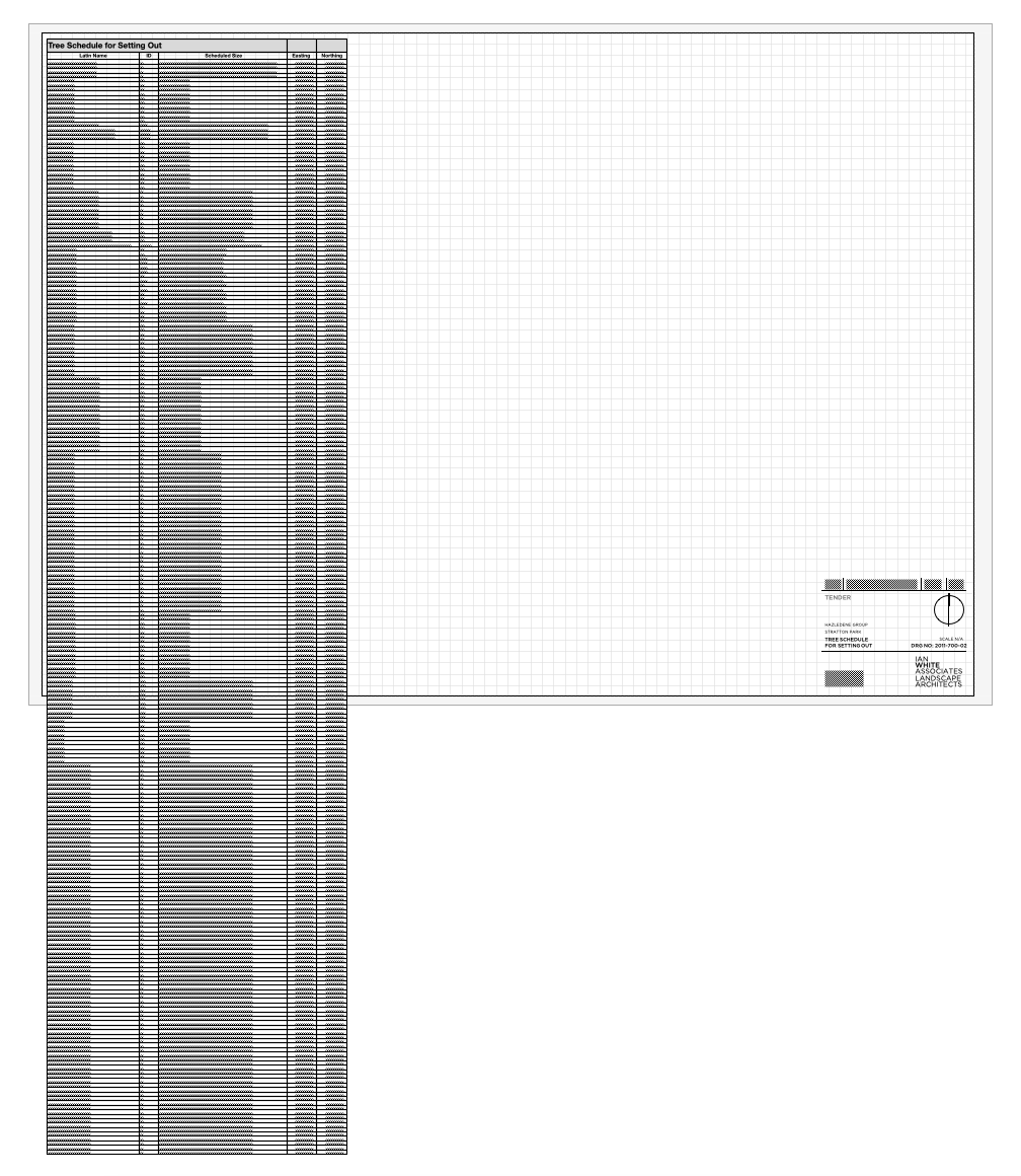
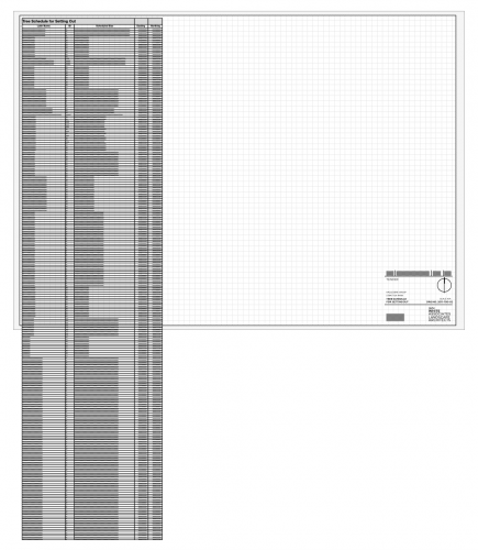
I have a reeeeeeally long worksheet generated from a load of data in my drawing. I want to display the whole thing on a sheet, but because there is so much information it doesn't fit on the page, and as such I want to split the worksheet (probably a couple of times, and ideally with the headers repeating!) so that I can fit all the info on one page neatly. I also want to still be able to recalculate the worksheet. Is this possible?
-
Did you manage to get anywhere with this @bgoff?
-
Thanks @Tamsin Slatter - I've already emailed the file to Bryan, but have uploaded to Cloud Services too. As I've explained to Bryan, the positioning I have in the file currently isn't technically geo-referenced, but the X position directly relates to the Easting position of British National Grid, and the Y position directly relates to the northing, accurate to millimetre precision - so if georeferencing is likely to move this at all or change the accuracy of the current positioning I don't want to go there, as I need to be able to use the drawing for Construction setting out for a Contractor to this level of accuracy? It's an exciting tool though so I'm hopeful I can use it!
-
@bgoff Thank you - advice much appreciated! Think my file is too large to send... but if there's an easy way and this helps, happy to send you a copy.
-
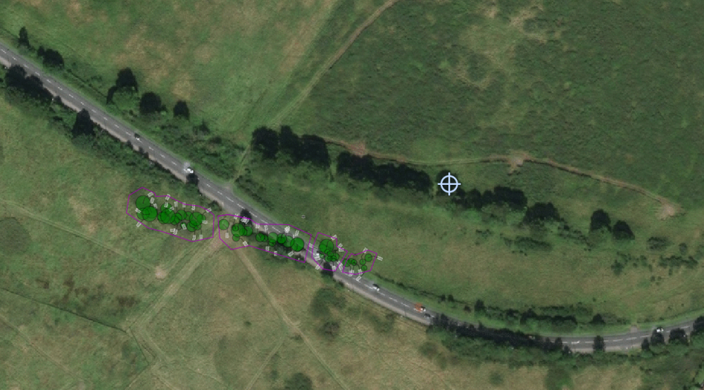
Thanks @bgoff - but I'm still struggling with this? I'm toggling geo referencing on for each layer. This allows me to move the internal origin without automatically moving my drawing. But I'm getting close to the right results but not there! So just trying to establish the workflow? Right now I am: - Toggling all layers to georeferenced - Using 'geolocate' to move the internal origin to a point at which I know the lat and long values - Using file > document settings > georeferencing to put in those lat / long values. Below screengrab of the results I'm getting - you can see the line of existing trees on the aerial vs the drawing. Any help gratefully received!
-
Thanks both - the problem I'm having with the geolocate tool is that is seems to move my drawing along with the internal origin? If I choose a point I'd like the internal origin to be - for example using a stake tool - and then use the geolocate tool to move my internal origin to this point, my drawing seems to move in relation to this as well? Does that make sense?
-
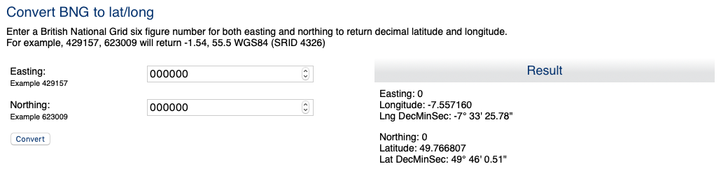
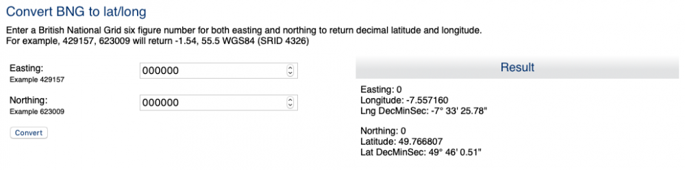
I've upgraded to VW2020 and as a GIS champion, I love the look of the geoimage tools and being able to tap into these libraries! However - I've opened an existing file, which is located correctly in terms of X, Y location as E, N location in relation to British National Grid. I want to change the geo referencing settings in the file to pick this up, and I've got the EPSG code 27700 - but I seem to need to also input the lat / long of the internal origin? This is an issue for me because I've already centred the drawing on the internal origin, which is at something like X: 270545.936m Y: 846170.209m - i.e. not an easily convertible integer. I'm sure I could find an online converter, but I don't want there to be any issues with conversion, because I need to use my file for construction setting out - so I need millimetre tolerances on the co-ordinates. British Geological Society only convert to the nearest metre. Does this mean I can only do this with new files - like set the 0,0 origin to the attached lat / long settings before drawing anything? Or am I missing something?
-
Drawing information moving miles away...
lisagravy replied to lisagravy's question in Troubleshooting
Exactly right! - so we had this problem again and issued the file to Vectorworks for review, and this is what they came back to say - that we'd saved one of the references while in a 'rotated plan' view, which had caused this issue. Glad to know we're not going insane! -
Drawing information moving miles away...
lisagravy replied to lisagravy's question in Troubleshooting
Thanks - we fixed the one that caused us issues yesterday just by manually moving all our drawing information back to the original position... but I will send through the next problem file(s) we have if that's ok. -
Drawing information moving miles away...
lisagravy replied to lisagravy's question in Troubleshooting
I'd say maybe if it was one of us it could be someone taking a shortcut or accident, but that it's happening to three of us separately, when we're not really crossing over in terms of working on each others drawings, it's quite hard to believe? We also have a few strong opinions in the office about always importing into a blank file, and it's been part of our workflow for a long time with no problems - we've only really started to have this issue since upgrading to VW2019? -
This has happened to a few of us all working on separate drawings now - our drawing information sometimes seems to transport itself way way off grid, with no particular pattern as to why? Can anyone shed any light on this? In terms of our workflow, all of our drawings are set up initially using design layer viewport referencing, to reference in information such as topographic survey, architects / engineers layouts etc, from separate Vectorworks files. All of these referenced layers are set to 'Centre first import, align all subsequent imports' when initially importing into their own files from DWG. Once all of these design layer viewports are referenced (and sense checked that they are in the correct place and suitably stacking on top of each other,) we are then choosing to centre drawing on internal origin, before we begin adding our own information. We then use the design layer referenced viewports as a base to work from to inform our own design, which we draw on a separate layer(s) but in the same position, often snapping etc to the referenced layers and turning things on and off. Sheet layers are created with annotations etc, using both our own layers and the referenced layers. The file can be used for days or weeks working correctly. But then, suddenly we will notice that a sheet layer is only showing annotations and any referenced layers, with none of our own drawing information. The design layer references all remain in their original position, but our drawn information is appearing anywhere up to 250,000km away, and requires to be moved back into place. Is there a reason for this / something we can fix in our workflow to avoid? Or is this a bug of some sort?
- 7 replies
-
- 1
-
-
- origin
- references
- (and 3 more)
-
Is it possible to 'bind' a Vectorworks drawing with xrefs on export, so that all the xrefs are absorbed into one single drawing file - while also retaining a Vectorworks format rather than exporting to DWG? I know when you export to DWG, the option exists to 'Export Design Layer Viewports as separate files', which provides the option of this function in the dwg export. In this instance, the consultant I want to send my files to also uses Vectorworks, so I don't need a DWG export - I just want to 'Save As' or export a Vectorworks file as a copy essentially, but in a bound version with all the xrefs included. As a workaround, I can delete my references and absorb the content - but without first saving a copy of my file, this affects my original referenced file, which I want to keep set up in it's current state. I just want to essentially 'package' the information as an export so it can be easily transferred to someone else also using VW. Is there an easy way to do this that I'm missing?
-
Perfect! Thanks. It is under modify, rather than on right click as for a polygon. My example has the same plants in each, but would be good to see if could add different plant groups and merge them...
-
I third this - necessary on almost every project and really difficult to achieve at the moment via workarounds.
-
Is it possible to add two landscape areas together (in the same way one would add two adjacent polygons) to allow a single tag, properties etc? I don't seem to have this option on right click, and can't convert back to polygons to add together...
-
Thanks @Tamsin Slatter - ideal!