
lisagravy
-
Posts
203 -
Joined
-
Last visited
Content Type
Profiles
Forums
Events
Articles
Marionette
Store
Everything posted by lisagravy
-
I've had a look at camera match before... and it does look fab for illustrative purposes! It's just that I need to be able to work to a stringent methodology in terms of demonstrating no skewing etc has been applied to the model to make it fit the photo? And also as we're not always working with buildings / urban settings, it can be difficult to define the lines of each plane in landscape photographs. The idea I was trying to work with was that if you take a photo from a particular co-ordinate point and height in the real world, with a set camera lens / angle of view / other definable camera settings, you can then replicate these settings within a Vectorworks camera, and the rendered export should be at the same scale / orientation as the photo? Which could then be combined in photoshop / another software?
-
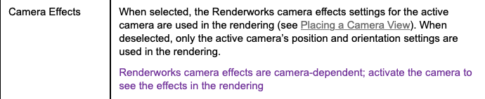
So I found the camera effects tick box. It's in View > Rendering > Custom Renderworks Options, which is only an option when the camera object is selected. I found this Vectorworks link to be more directly helpful than the series of 37 youtube videos detailing the full rendering process! Thanks anyway though. Looks like without this setting enabled, the majority of the camera settings aren't incorporated into the render, which is maybe why I'm having issues replicating a 50mm scale with angle of view etc! Will give it a go.

-
@Zeno Thanks, will have a watch. When you say render with a style with renderworks camera set to on, does this just mean use a renderworks-style render setting, rather than OpenGL?
-
@Zeno This is similar to my workflow: - create a model in Vectorworks - set a renderworks camera on position, 50mm FL, angle of view etc. (I wasn't sure whether to use perspective or orthographic projection.) - render a viewport from the camera (is there a setting to turn camera effect on? Where is this?) - export the image for external work, to overlay the image onto the original photograph. BUT, when I overlay the resulting model on the photo, it needs a fair bit of rescaling and skewing / warping to fit properly over the image. I wasn't sure if I was missing settings somewhere to make the model export from the camera more reflective of a real 50mm camera photograph in terms of scale and perspective.
-
@Zeno- I need to be able to use a 50mm focal length camera to take a photograph, with an exact horizontal angle of view, to use as the base image for a photomontage - so basically I want to take a model from Vectorworks and overlay the exported render image from the Renderworks camera onto the 50mm photograph in Photoshop? I can't edit the perspective of the photograph at all, so I want to make sure the model to be in the same perspective as the photograph? Does that make sense?
-
In terms of the projection settings in Renderworks Camera, the options are limited to 'perspective' or 'orthographic'. Which of the two would be the most reflective of the projection of a photograph taken from a standard 50mm fixed focal lens camera, if I wanted to overlay my model onto this? (without using the camera match feature?) Professional guidance on visualisation of developments refers to both 'cylindrical' projection, which maintains vertical lines and scale across the image; and also 'planar' projection, which is that as captured in a single frame camera image. Am I right to assume cylindrical would be best suited to an orthographic setting in Vectorworks, and planar would be best suited to the perspective setting?
-
Yes please!
-
I have a geo-referenced file, with geo-referenced data imported. The data in my file all sits in the correct place when I add a Geo-image to check the geo-graphic location - however, the file has never been 'geo-located' - so the internal origin is miles away from the data. If I try to geo-locate now, the data in my file moves position to retain it's offset position to the internal origin, which I don't want. I've tried this with both the geo-referencing turned on for all layers, and also turned off. Is there a way around this?
-

Georeferencing with Design Layer Viewport References
lisagravy replied to lisagravy's topic in Site Design
@Tamsin Slatter - just working this through on a new file, and while it will work a dream in SP2... there are a few extra steps for the SP1 method. Reason being - if I have Target File 3 as a blank file, without the SP2 'Align User Origin with Georeferencing Coordinate System' dream tool, I can't locate a GIS stake in the same location as the Internal Origin of the xref files, because my XY don't align yet so I don't have any way of positioning it. I have to use the search geolocate function to find the site, then geolocate on a random point - then set the user origin manually to align with the co-ord system to allow me use of the XY positioning. Then I can set a stake tool with the same co-ordinates as the Internal Origin for other files, and geolocate again to this point. However, this messes up the user origin again as it's position is set in relation to the Internal Origin... so I have to set the User Origin back to the position of Internal Origin, before I can reset the user origin manually again to align with the co-ord system. It works, but it's convoluted! When is SP2 coming out again?? 🤪 -
I realise this post is out of date now but just wanted to throw in a tuppence worth. Previously we've used (Q)GIS at Planning and feasibility stage, to make use of extensive datasets which are available - particularly base mapping but also overlaying landscape and planning designated and protected areas, terrain data, ZVIs etc. in initial site analysis and planning reports. We've then used Vectorworks concurrently for early design drawings and diagrams at feasibility and planning stages. Our Tender and Construction drawings evolve from our early stage Vectorworks drawings, and our GIS drawings tend to get archived. The recent 2020 release is good for us as it provides welcome integration between what have previously been separate technical exercises required for the same purpose early on in a project. We can now utilise additional base information straight from Vectorworks, (such as aerial and base imagery) and import and read the data attached to shapefiles to be read in context with our design. I'd second @unearthed comments on the likelihood of continued GIS use for large scale analysis - I wouldn't want to import national shapefile datasets to Vectorworks - but complementary systems allow better workflow between the two.
- 2 replies
-
- 4
-

-
- gis
- site planning
- (and 3 more)
-
GIS Programs Similar to Arc GIS (ROW info)
lisagravy replied to HEengineering's topic in General Discussion
Have a look at QGIS? It's an open source GIS software. You would need to input or source all the ROW information yourself, it's not going to collect the data for you - but if you contact the county GIS departments they may be able to send you GIS shapefiles from their systems which you could load in, combine and amend as necessary? Then you'd at least be able to build up one single source. -
How-to: import GIS Data (KML / SHP) into Vectorworks Spotlight
lisagravy replied to mjm's topic in General Discussion
I'm using Landmark, which does support importing GIS data such as shapefiles, so I can't help with a Vectorworks based solution I'm afraid - other than to ask if you are sure Spotlight doesn't support this - check that it's not just that you need to add the tool to your current workspace. If it doesn't support this, you can use an open source GIS software (QGIS) to open GIS data, review the shapefiles natively within a GIS system, and then export to DWG if necessary? And at least that way you can see if the full data set you need is within the GIS file you've been provided with and it's an issue with DWG conversion - or if the shapefile doesn't contain all the information you need and you just need to request another SHP with the right data in? -
@JeremyLondonRMLA I'm not sure if this helps or if I'm misunderstanding your question... but incase it does. We regularly import non-georeferenced CAD data, which is located via user origin. If you import this in a geo-referenced 2020 file as per workflow for previous versions, and also import shape file data to the same file, the data doesn't align automatically anymore, where previously it would have. This did stress me out a bit when I first noticed it. However, if when you import the CAD file, you select the 'this file contains georeferenced geometry' tick box, this automatically sets the 'advanced' settings to 'align with internal origin', and projects the CAD information to the correct geographical location in the file based on it's own user origin. This then aligns fine with shapefile imports, and exports the data geographically in the correct place too. If you try importing a CAD file with these settings, and compare the same import using the previous workflow 'centre first import, align all subsequent imports', you'll note that the X and Y positions of the CAD data are different depending on which workflow you use. Previously the X and Y were reflective of the co-ordinate positions, where with the new geo-referencing workflow they aren't. If you want the X and Y to also remain reflective of geographic position (e.g. if you want to be able to export CAD data again as well as GIS data,) you need to manually adjust the User Origin to align with the georeferencing origin, either manually or (hopefully soon!) with the SP2 tool. This then allows you to import and export both GIS and CAD data with the correct positioning, and also take advantage of the benefits of the geo-referenced data within Vectorworks, which I think overall has improved CAD/GIS integration?
-
Exporting Shapefiles from Georeferenced Files
lisagravy replied to lisagravy's question in Troubleshooting
@Tamsin Slatter I LOVE the poshness v normalness classification! 😂 Weird you can get it to work. I've tried on both my machine and a colleague's, and when I hit OK to export the shapefile, the dialogue box goes away but no shapefile is ever created? Can chat next week, I'll maybe send you a basic test file! None of my tests are as fancy as yours though, literally just using a single polygon. Have a good weekend, and thanks very much for all your help on this!! Really excited to roll it out as our new workflow ☺️ -
Georeferencing with Design Layer Viewport References
lisagravy replied to lisagravy's topic in Site Design
@Tamsin Slatter - amazing! Thank you. -
Georeferencing with Design Layer Viewport References
lisagravy replied to lisagravy's topic in Site Design
Thanks @Tamsin Slatter ☺️ Much appreciated! -
Exporting Shapefiles from Georeferenced Files
lisagravy replied to lisagravy's question in Troubleshooting
Thanks Tamsin 😳 -
I'm having issues exporting shapefiles from VW2020 files which have the geo-referencing settings switched on as default. If I select a simple polygon within a georeferenced / geolocated file, and navigate to File > Export > Export Shapefile; I typically then would choose selected objects, keep projection, and write .prj file (and choose all additional object data). When I do this and click OK, I am prompted where to save the file, and click OK again. Nothing happens, and no file is generated. What I'm having to do as a workaround is open a new file, turn off all the geo-referencing settings, copy / paste in place my polygon to the corresponding X Y location to the co-ordinate position, and then go through these steps again for a shape file to actually output? Is this a bug or is there a flaw in my workflow somewhere?
-
Georeferencing with Design Layer Viewport References
lisagravy replied to lisagravy's topic in Site Design
🙈 Thanks @Tamsin Slatter - I must be your most irritating customer at the moment! Everyday a new georeferencing query 😂 -
I have two files containing baseline information for my project - Topographic Survey and Architect's Layout. Both have been imported from DWG into their own new VW files, and georeferenced according to the procedure detailed in the previous georeferencing thread on this forum. I can Geo-image in both of these files and the drawings fit beautifully over the site. I now want to reference the information in these drawings into a new master file, using the design layer viewport referencing system, so that I can use the information to inform my own drawing. However, when I try to do this... while the X Y positions of the drawings remain correct, the GIS stake shows that the design layer viewport referenced layers, when created, are nowhere near the geo-located positions set in their original files. Am I missing something really straightforward? Any help much appreciated.
- 11 replies
-
- 1
-
-
- georeference
- georeferenced
- (and 3 more)
-
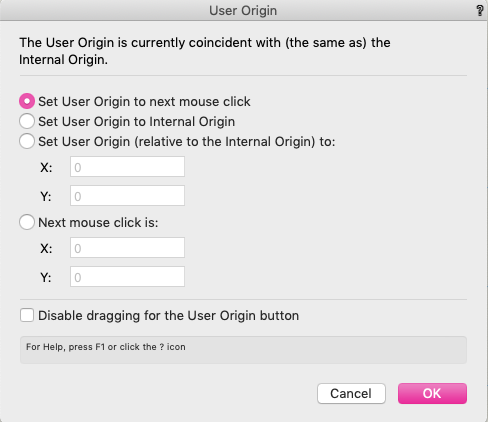
This is pretty similar to what I did, but I shortened a step... which may be incorrect but thought I'd share just incase! At step 6 - Tools > Origin > User Origin - even after I geolocated, the top of the prompt box for this tells me "the user origin is co-incident (the same as) the internal origin". So if you have this as well, it might save you a click 😂

- 28 replies
-
- 1
-
-
- gis
- georeferencing
- (and 3 more)
-
Thanks so much for your investigation on this @Tamsin Slatter - it's massively appreciated, and the results will make a huge difference in our ability to integrate our current VW CAD work into a GIS system! I've undertaken similar testing and it's worked really well. One of the interesting parts of this in particular for me is that IF aligning the User Origin in metres maintains accurate X, Y positioning within a geolocated file... by implication then once this is set up, we could easily move GIS stakes etc and other objects in Eastings and Northings also by utilising the X,Y position in metres, and still be able to accurately geo-reference and extract the lat/long values if we wanted to - which is a HUGE development. Really exciting stuff! Also delighted to hear about the integration of this feature in SP2! Thanks Engineering team!
- 28 replies
-
- 1
-
-
- gis
- georeferencing
- (and 3 more)
-
😂 Thanks! Also should say - I found this relevant resource on the Vectorworks University site (though it is American). https://university.vectorworks.net/mod/scorm/player.php?scoid=196&cm=302&currentorg=articulate_rise The first section relates to 2019, which is different so don't watch it because it's just confusing 🙈 but have a look from 22:45 mins into the video, to around 29 mins in, where they seem to manually set the user origin to match the geo-referencing co-ordinate system... which apparently is due to be an automatic option in SP2?
- 28 replies
-
- 1
-
-
- gis
- georeferencing
- (and 3 more)
-
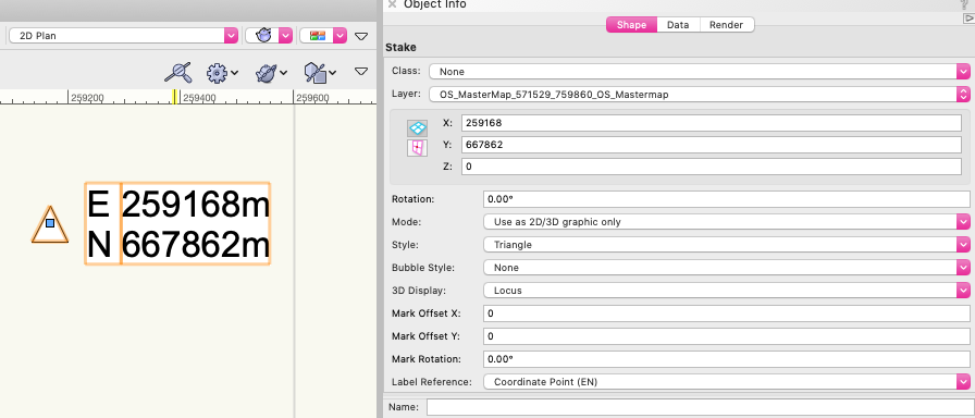
So my testing with British Grid so far is that the E and N don't unwrap back to X, Y if you have geolocated the georeferenced file to move both origins to the project data - they relate to the new X, Y positions relative to the origin, which don't relate to anything. BUT, if you move the User Origin in the geolocated file relative to British Grid 0,0... and then check the X,Y positions of a GIS stake which shows the E, N positions, I can get my X, Y to match E and N, and export to DWG perfectly? But yes, my mind is a bit fried by it all, a large glass of wine / whisky is required! (Also note for this that the co-ordinate precision is set to 0.0001m)
-
@Tamsin Slatter Thanks! I do get that typically when you are in a georeferenced file you want to be working with the projected co-ordinates (E, N) and ignore the X, Y as irrelevant. Just thinking (hoping!) that specifically for British Grid, as the projected co-ordinate system is actually projected flat onto an equally spaced grid of metres, in this particular case the X and Y might also remain reflective of the projected Eastings and Northings when displayed in metres? (as it would obviously make my life much easier 😂) Thanks for checking it out.