


Ross Harris
-
Posts
346 -
Joined
-
Last visited
Content Type
Profiles
Forums
Events
Articles
Marionette
Store
Posts posted by Ross Harris
-
-
I'm Auckland based and use the council gis regularly - but only for initial feasibility. The council gis is very ballpark in terms of levels - at worst it's over 1m out compared to a site survey and on one site, the sewer and manholes were 6m away from where the gis put them. My advice is to not use the gis data for resource or building consent design work - get a survey done. Also don't mix surveyors levels with the gis levels - the inaccuracies of the gis with accurate survey levels will skew a site model, hence the odd contours. Take note of the disclaimer you have to agree to - it goes to great lengths to highlight the data is 'informational' and that all liability rests with the user of the data. You are potentially opening yourself up to liability relying on the gis.
ISSUE 1: You can download a georeferenced DWG from the gis - this makes initial creation much quicker. The boundary lines are from LINZ, so are accurate, but the contours are ballpark. The contours (depending on the gis dataset available for the area) can be big steps, so you won't get the detail of a site survey. It sounds like you have mixed the babbage spot levels in, which as I mentioned above, will make the site model inaccurate. Paying for a survey is money well spent and very much a get out of jail free card.
ISSUE 2: Model your house FFL on a design layer at 0m elevation and then create a design layer viewport (DLVP) to send the 'house' as a 3d viewport to the site model. That way you can grab the DLVP and position it where you like and it will report the actual vertical height to the FFL in the site layer. My 'house' layers are storey driven, and the site layer is not associated with a story, so I create a viewport with the house layers in the usual way, but send them to the site layer - not a sheet layer.
Your site layer should be set to 0m elevation so that a gis or survey I port will always report the correct levels.
Elevation benchmarks - I usually use them in control point mode in the annotation space of the viewport (for flexibility) taking the FFL of the DLVP height in the OIP from the site model layer. From memory, I think elevation benchmarks will report the height of a DLVP... Will have to test 🤔
ISSUE 3:
1. The red lines are a cube representing the top and bottom extents of the site model.
2. The skirt extents are in the site model settings - you can have it go to 0, a set elevation or it can be to the lowest contour of the site model - which is good for sites at 100m elevation for example. Also good to allow the site model to extend if you are doing cuts that go below the exisitng site contours.
Depending on how you have set the contour multipliers in the site model settings, they can be different to the the gis - also the interpolation VW does creating the site model can create contour variations. Also mixing in survey data with the gis data will cause this to go whacky - as noted above.
I can't overstate getting a survey done. An accurate model starts with accurate data, and in the worst case, can save you a day in court .. I will turn a job away if the client won't get a survey done. This is even more critical and mandatory in flood zones since the flooding last year.
-
 3
3
-
-
Although that achieves the result, the update has resolved one workaround (contour units) and added another with the steps to create a label less site model to use the 'add contours' button and tools.
One takeaway is that it is less onerous that tricking the site model to stay in a different unit to the rest of the project units... but still - how is a new user supposed to work this out?
Also, 'custom label placement' should be renamed to 'Auto contour placement' There's nothing custom about that preference in the dialog. The user should be able to turn this off and still be able to use the tools activated by the 'add contour labels' button in the OIP.
So, for update 5 or VW 2025, can we please:
- Rename 'Custom Label Placement' to 'Auto label placement'
- Allow the 'add contour label' tools to be used when the above pref is off.
Once that's done, we just need to property lines to be data taggable and it will be just about perfect. 😍
-
1
-
What we need here is a pin object option, with lock remaining a full lock up - this would be useful across the board.
-
3
-
-
We almost got there....
The ability to place contour labels under a poly line is fantastic... but... why oh why, can we not have an easy way to start with no contour labels and allow the polyline mode to place them where we want and these be the only contour labels on the site model? Am I missing something?
For all the amazing capabilities in the site model that really stands VW apart, its things like this to document a 2d plan that completely let the whole show down. That and property line annotations - these should be data taggable. The big R gets this stuff right..
Generally, the tweaking to the site contour labelling in this update has been fantastic and has been wished for many times on this forum over the years... but it just needed to go the extra millimeter to give total control of labels to the user. 🥹
Please.. in Update 5 can we have the option to have no contour labels on the site model but still use the polyline mode to place them?
-
2
-
-
@napwszzm rerun the updater and you should see update 4a - works a charm.
-
4
-
-
NZ's a special place 😉 😁
-
1
-
 1
1
-
-
Sorry - should have mentioned, I've run repair on the updated install and the clean install with no change in result.
-
@JuanP nothing - I double click and get the busy cursor for a couple of seconds and thats it. I've rebooted and also done a clean install of VW from the customer portal after doing the update from the updater. This is happening on my office and home PC's where 3.1 was working perfectly.
-
I've installed the AU/NZ version of update 4 and it won't even launch..
-
1
-
-
I prefer to do floor finish slabs on top of the structural slab so I can schedule/quantify all the floor finishes. Plus, all our floor finishes except polished slabs are inside walls, so is 'construction correct'.
-
2
-
-
Twinmotion 100% for presentation exteriors. Enscape for something quick - mainly use this for interiors tho.
-
1
-
-
- Popular Post
- Popular Post
Yep a totally reasonable question. All software has it's pros and cons... Now that we've got Revit (after an 8 year sabbatical) it gives a refreshing perspective give on things generally. Both do exceptional things.
The unfortunate side effect of raising prices is that it becomes within distance of the competition, you naturally start looking at the alternatives and what they can offer.
-
5
-
2 hours ago, High_Viz said:
every day is a school day
100% agree on that! Great detective work on the AVX issue too.
-
1
-
-
Go to a system builder for your new machine - the big box brands (dell. HP, etc) always scrimp on a system component somewhere to enhance their profit margin to the end users misfortune.. not to mention the insidious crapware they preload to 'assist'...
You don't need a workstation spec machine - a hot gaming rig will do the business. I usually upspec as much as I can with the CPU and memory - hard drives and new graphics cards are easy to add in or swap later on for a bit more longevity.
-
1
-
-
It might have the speed on paper, but it's the architecture of the components. A system from in 2009 is practically prehistoric compared to systems in the last 3-4 years. Bus speeds, memory bandwidth, memory type (DDR3 in your rig vs. DDR5), PCIe lanes are considerably faster on current cpus, which the software (windows, directx, drivers, vw) in 2024 is written to leverage.
I had the same issue years ago with my old 2008 cheese grater Mac Pro - great machine, but the architecture just let it down and was put out to pasture in 2015.
When looking at minimum system specs, you might need to consider the other things you'll be using, like chrome running lots of tabs, pdfs open in acrobat, outlook - known resource hogs. System specs only consider the software they represent, not real world use cases of a computer with multiple programs running - which they can't - no vendor can account for individuals computing workflows/habits.
-
2
-
-
Your Xeons came out in Q1, 2009.. so pretty old tech. Maxon recommend a Kaby Lake minimum - that's a 2016 release
Last ditch options are downloading the latest NVIDIA driver and running windows update to get most current win 10 version (updates directx at the same time) that will run on the pc. Failing that it's got to be compatibility issue with old hardware.
You'd probably best to start thinking about an upgrade for VW 2024 and newer - the good news is you won't need dual CPU or Quadro to make VW fly - a current i7 14700k or a Ryzen 9 7900X3D with a rtx4070ti super (our two office rigs have i7 13700k/rtx4070 and i9 13900k/rtx4080 respectively) will make your current rig look like a bicycle being overtaken by a Veyron on the Autobarn - for less than matching your current config with today's products (dual Xeons, quadros,etc) - unless you need this config for another use, that is. My home home rig is a Ryzen 9 3900x/rtx3080ti (CPU is from 2019) and is no slouch using VW - no maxon plugin errors on any of these machines or our laptops.
-
1
-
-
This is something that should be updated when the drawing set is published. Other softwares manage this - at the moment it's just another thing to forget when under pressure. At the very least it should be significantly easier than the process to update them all as noted above.
-
Wow! I've not seen 24gb sticks before... Just checked my usual retailer and there they are! They certainly weren't there a month ago when I specified a rig - most sets are on back order so I presume it's a recent development/availability here. There's more 96gb sets coming through than 48gb though, and not to stupidly priced.. which is great for ITX builds with only two slots, which I'm keen to do
Which makes your issue puzzling cos they should be interleaving... 🤔
I just built a 14900k/4090/64gb rig late last year to run VW+Interiorcad and Enscape with with two 42“ monitors for a colleague... It doesn't break a sweat; Interiorcad can can be heavily taxing with a buildings worth of fully detailed cabinetry on top of piping out to Enscape for real time rendering.
Is there anything loading at startup that's sucking the life out of the machine?
-
2
-
-
It's probably not the ram clock that's the issue... 48gb is an odd number, meaning that the two sticks are not a matched pair and can't read and write in interleaved mode. Which as far as I can recall means it writes to both sticks simultaneously - when it can't there is a reduction in speed.
I'd look at getting a matched pair of ram sticks with the rated clock speed for your CPU. Matched pairs go up in multiples - 16gb, 32gb, 64gb etc.
If you've not overclocked, DDR5 5600 or higher(assuming the board is a DDR5 board) should do the business.
We've got two matched pairs of 32gb DDR5 5600 for 64gb in our 13900k rigs and they are flying with multiple acrobat docs, photo viewer, chrome tabs and occasionally YouTube running.
-
1
-
-
Its 90% there.. except I can't fillet the tread cleat to the tyre wall. it will do one, then can't do anything else. Also I imagine adding additional detail like branding and other info that follows the tyre wall curve will also be tricky/impossible in VW.
Blender is looking like a goer.. so much cool stuff, like a plug in that does a weld style fillet..

-
1
-
1
-
-
Just search on YouTube 'how to model a tractor tyre' and seee how advanced some of the modelling tools are in other softwares...
I'm doing a scale model tractor as a 3d printing project... Started it in vw, but I'll have to go to blender.. or stump up for Rhino (it's totally a business cost ..)
-
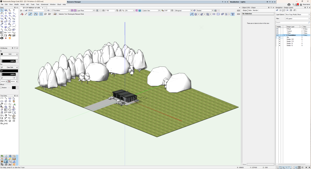
Funny you should mention that... mine has lapsed and in the VW screengrab above is exactly what you are left with - all the resources (low poly proxy's, textures) that were inserted into the VW file. Once you renew it'll render as normal.
-
11 minutes ago, line-weight said:
That sounds much tidier than the Datasmith export system to me ... if it works.
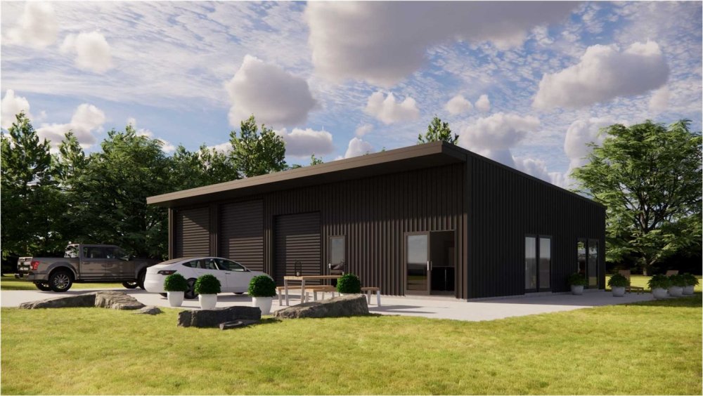
Oh it is... it's a brilliant workflow. It's just not quite there for me compared to the output I get in TM.. If you need to do renders on the fly I can't rate it highly enough; I usually wait until I get to a point in the project where its 'set' to render in TM, and any changes afterwards that will affect the render, I'll budget an hour or two to do a new TM render. That shed render above was literally 5 mins of work.. and that was just to drop trees, cars and landscaping assets plus adjusting the specular setting on the glass; so for clients who don't expect that sort of work for small jobs like that, it's a bonus and blows their socks off for virtually no work. To do that in TM is probably 30 mins or so swapping textures, painting grass and finding/placing assets.
Gotta say, I love the depth the built in Enscape sky projects. Just adding some Cirrus makes it feel huge.
-
2
-
-
- Popular Post
- Popular Post
Enscape is 100 'in' VW. It doesn't manage its own geometry or textures - it just renders what's in your VW model - it's basically a floating window (dual monitors are a must). In recent versions you can manipulate assets in the Enscape window, but any change you make there happens in VW as well. You have the choice of placing assets from the Enscape library into VW or if through Enscape window, the asset will appear in VW as well as a low poly proxy.
Same with textures - if you download an Enscape texture via the texture library it appears in the resource manager to apply to the object; editing a texture also edits it at the RM level. Some of the best grass I got in Enscape was using the VW grass shader.
-
7


Process…
in Architecture
Posted · Edited by Ross Harris
There's so much missing or refined that needs to be prioritised I feel. As Matt alluded to VW being a global software, a framing tool risks being regionalised to be useful in a code compliance manner - a bracing tool (as an example) would be useless for us here at the bottom of the world if developed for a 'predominant market'. Trusses here can only be engineer designed or provided by specialist software then made by licensed fabricators. All timber framed houses and truss fabrication here are designed (post council approval) by detailers using predominantly Mitek Sapphire in the pre-nail factories, loaded on a truck and delivered to site. Designers here only need to cover the bigger picture stuff with specific detailing to get building consents. Trusses can have complicated loading paths to foundations and are best left to specialist software and engineers.
We also have steel framing gaining in popularity - which is again detailed for prefabrication in specialist software like framecad that talks directly to the machinery rolling the frames.
To be able to cover all the legislative requirements, loading and structural codes around the world and being able to certify compliance would be very diffcult or next to impossibe for software like vectorworks. I can almost guarantee that the sketch up plugins are more for looks or will pump out a design that meets code in a specific locale. If vectorworks were to focus development on a specific region would likely alienate others - especially if this developmet were to raise the cost.
My vote is to leave this to specialist software. We just need to get everyone here interchanging with ifc..