


Matt Hall
-
Posts
83 -
Joined
-
Last visited
Content Type
Profiles
Forums
Events
Articles
Marionette
Store
Posts posted by Matt Hall
-
-
On 10/9/2023 at 10:51 AM, Matt Hall said:
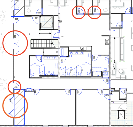
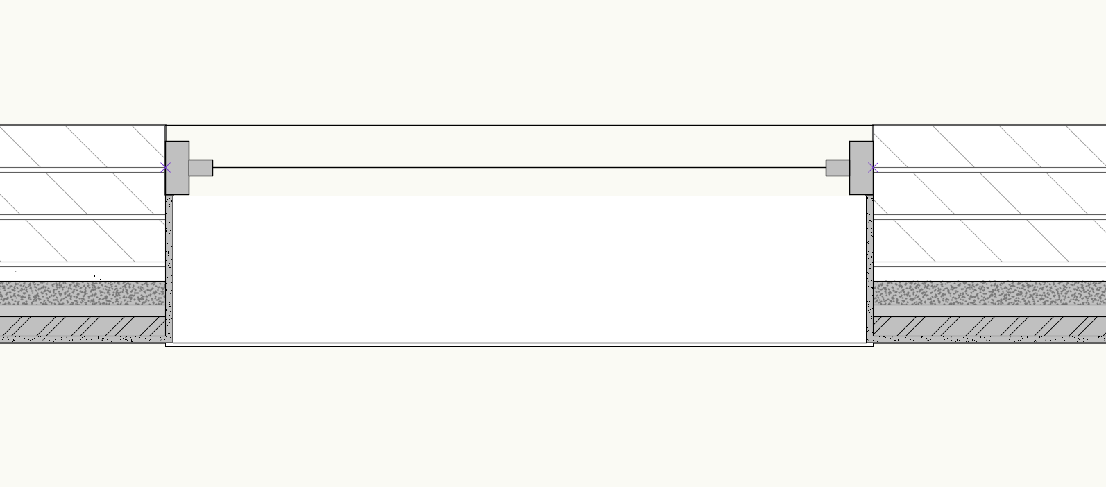
Any thoughts on a work around for this condition?
or is there something I am missing?
When I change the wall closure stetting the wall opening goes to the outside of the frame as shown above
the fix
If I copy to another document, duplicate the wall with the widow, covert the copy wall to unstyled, fix the wall closure, then create new wall style and name it the same as the original, then copy it into the original document to overide the wall style in the original document then it looks right in plan. Simple?
The walls were created in a VW 2023 document. We have had several issues with editing door and window styles after upgrading to VW2024.
-
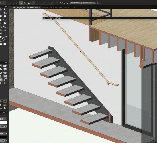
The new Rail Tool, Dosnt seem to work with outside stringer stairs
I had to convert the stair to a concrete stair, do the handrail and convert it back.
I had drawing it in plan then used the gravity tool on a different stair but had issues, most post hit the stringer but one or two would land on some other element that i could not find (lots of levels in this project)
PS how about adding a metal pan concrete stair tool to the options (very common commercial stair)
-
 2
2
-
-
After upgrading to 2024 I we have had some periodic issues with doors.
some seem to have disappeared. not right away. might be happening has we modify a wall style but haven't been able to realy see a pattern to when and why it happens
one time i moved a wall and the door disappeared, i did an undo. I could not move the door in the wall, i could not copy the door and past it somewhere else, I was like it wasn't there
I had to let the door go and copy it back in from an old backup
-
I have updated but not attempted to retry, I will give it a shot when I have a moment, Thank you
-
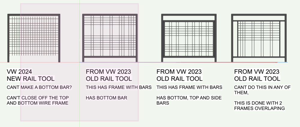
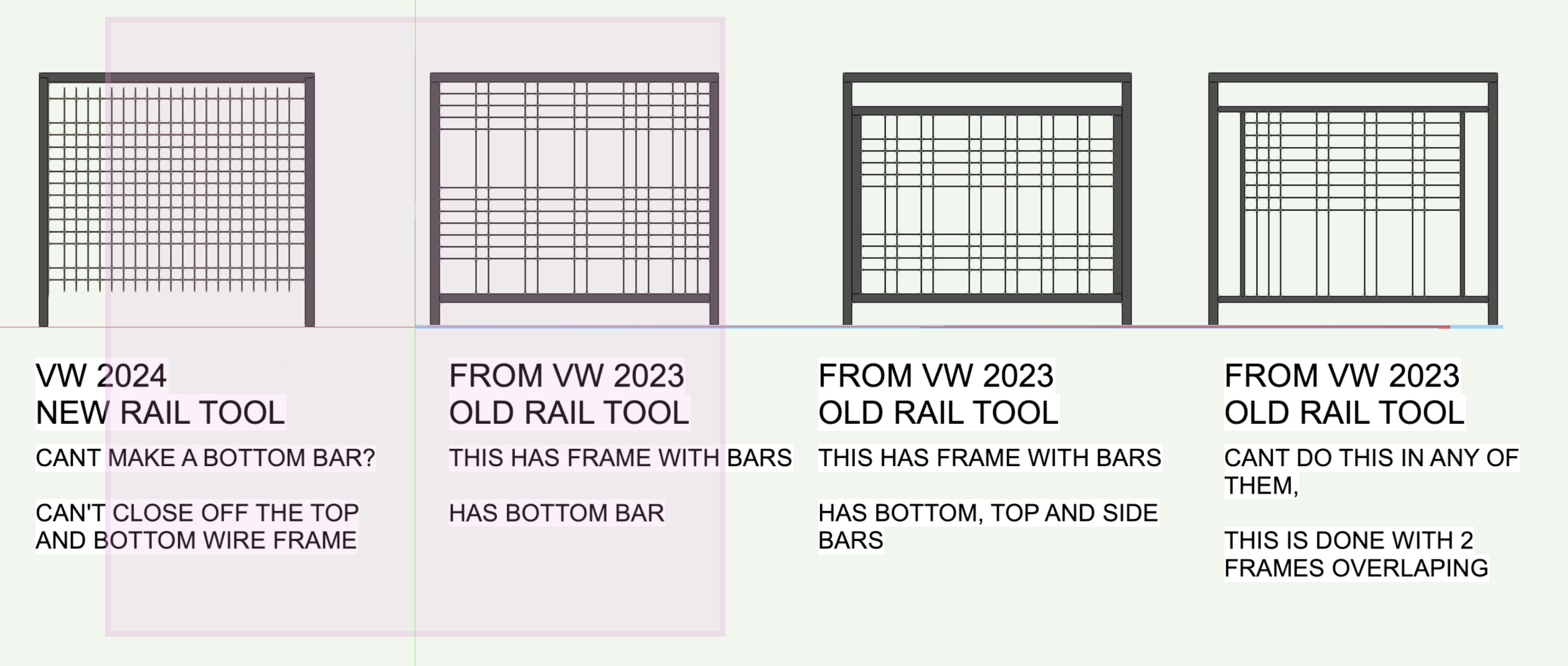
I cannot find a way to add a bottom bar to a frame made with the new rail tool. Ideally I would like to make a rail that has a frame panel in it (like the last example, this infill)
Am I missing something?
(sorry the Screen shot does not show the 2x2 wire grid well)
-
1
-
 1
1
-
-
Any thoughts on a work around for this condition?
or is there something I am missing?
-
Juan,
just sent you a file
Thanks
-
We are having real issues with the sill as well
the sill wants to be within the jamb, not the entire window
we are also using shared project files and get a lot of crashing while we save and commit. Seems to happen after we work with walls and windows.
when you crash while committing everyone gets locked out of the project file and we need to create a new project file from somones working file, losing the work that had not been committed.
We have had doors and window randomly disappear as well
We jumped into the wall and window upgrades and love what they can do now. But we have lost days of work scratching our heads and rebuilding files that seem to be unstable. I think its about the walls and doors windows
any thoughts
-
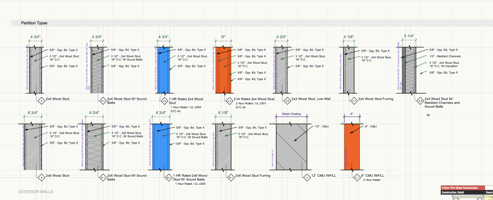
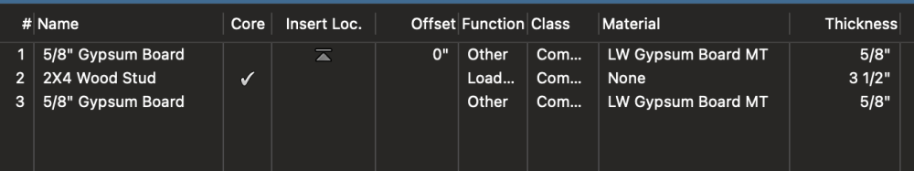
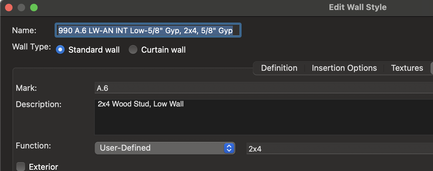
I would like to us visualization to show all 2x4 studs, 2x6 studs. I cannot find a way to have the visualization identify what wall uses 2x4 and 2x6
Any thoughts. Below is using visualization to ID fire rating. I would like to do the same for stud thickness.
this would be an internal review not construction documentation
I though i could use the "Function User-Defined or the wall style name. But i cannot find how to add these to the Visualization tool
Thank you

-
Thanks for the reply
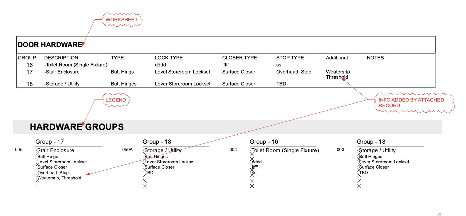
i recall many years ago adding a field to an object but I do not recall the circumstances, Your probably correct that we cant customize the hardware, it seems very locked down.
I did however have the same idea as EFA and added the field via a record. It does work but adds a second step, that makes if feel a bit fussy. just have to try it out to see how it works in a team setting.
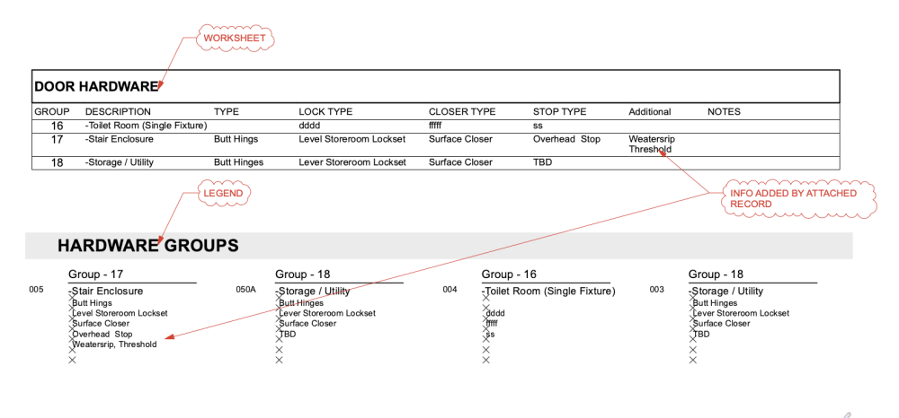
also used a legend to format the hardware groups the way wanted.
Thanks for the input
I can move ahead with this but if feels a bit like a mish mash of data that requires some finger crossing.

-
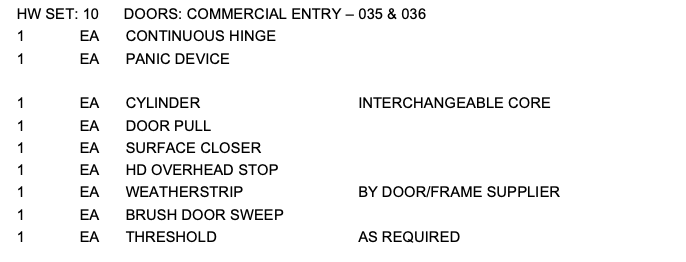
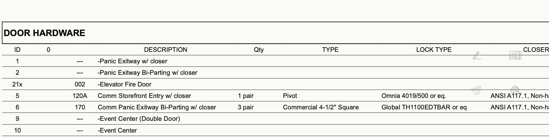
I am trying to make use of the Hardware sets as part of Door Styles.
To really use the Hardware set I need to include some items that are not part of the standard options. Example, weather striping or card readers. These could be dumped into the notes area but it would be nice to be able to include them in a proper format
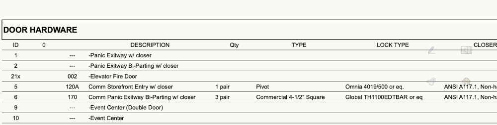
The next step would be to format the groups with the items stacked
(rather than like a schedule where the items are all in one line (
Preferred
this seems to be the default
-
Yes, the property line should be able to be just a line without fill.
-
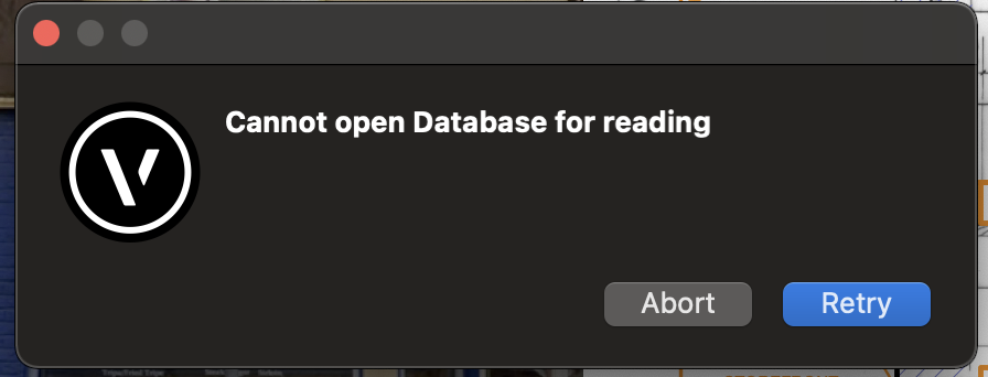
I am having trouble setting up Key Note database with project sharing. We keep our project sharing VW documents on the Vectorworks Drive. We have set up a shared workgroup folder on our google drive. the workgroup folder seems to be working for multiple users. I cannot get the notes in a place that is stable or accessible. after i think i get things set up it gives me this.
I have not found a step by step description, video or diagram that has helped me figure this out.
any direction would be appreciated
-
1
-
-
Right on
Did the polyline tool the did create objects, hardscape path object
Thanks thats the simple process i was looking for, in hindsight I should have figured that out.
-
1
-
-
Is there a curved double line tool yet?
The site model tools have come a long way and I would like to make a curving sidewalk but cant find a one step process to make a curving polygon
-
When I use a space object and select a finish to go into the field, it works great, shows up on the room finish worksheet or tag i have set up.
however if i edit the finishes to make a new finish option, all the fields change from what I had picked to some default. So i have to reselect the finishes i want to show up on the schedule. This makes this workflow unusable.
It's unrealistic to think you will not have to add or make changes to a project, and the point of BIM is to lock in information in one place.
Please let me know if i am missing something
Making a workflow with a BIM Room Finish Schedule should be a basic out of the box feature.
-
This is an issue for me as well.
Are there people using this feature to create and manage Room Finish Schedules. It seems unstable.
Would love what other are doing for work flows for finishes
-
I am very thankful
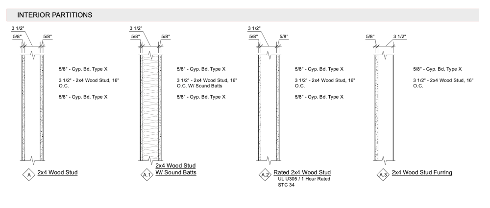
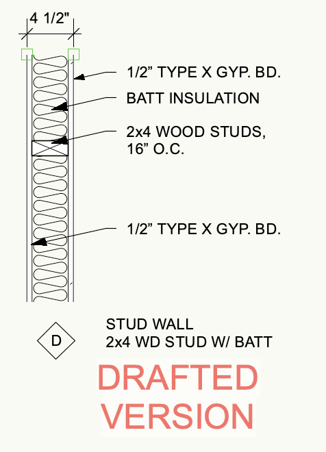
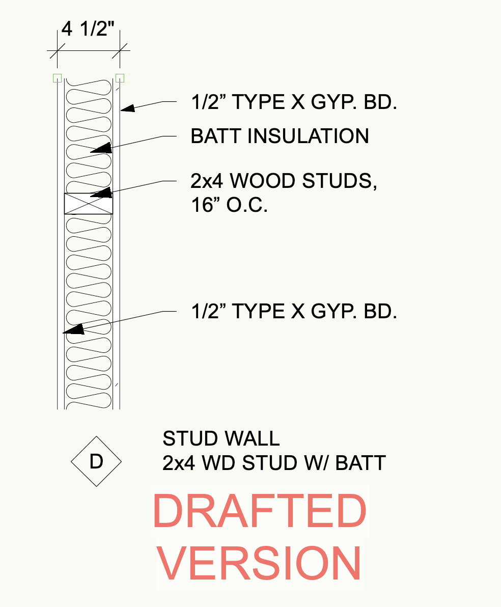
the screen shot is of a legend tool for wall types
This is very close to what I would have done if i drafted them.
(Below that is a screen shot of a drafted wall type legend)
All the information is now imbedded in my wall style.
very very cool
(I have been very happy about the impute I have gotten from people out there and wonder how they have time to figure this stuff out. I sill wish VW could have items like this prepackaged. Seem like this would be a basic for any architecture office.)
Thanks again
-
1
-
-
On 3/24/2023 at 3:08 PM, Pat Stanford said:
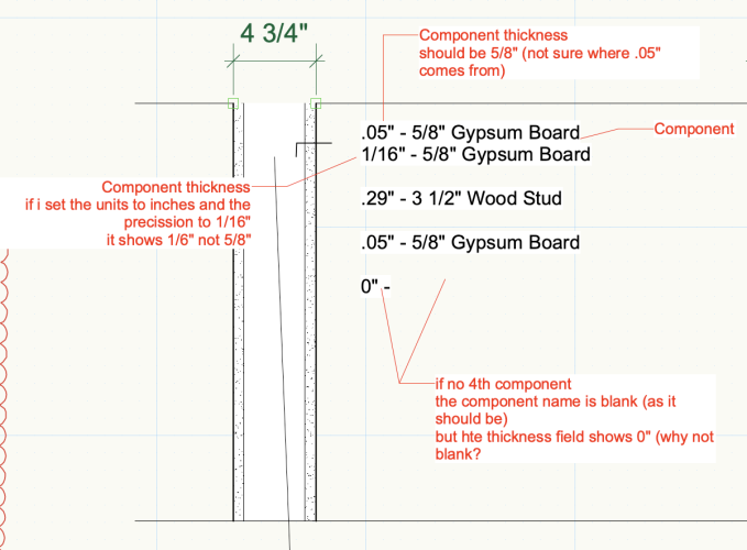
I am pretty sure that the thicknesses are reporting in decimal feet coming from the document units of Feet/Inches. Try setting them specifically to inches in the dialog box.
Why zero? Because zero is a number and blank is not a number and the formula you are using is returning a number. 😉
The workaround is to use a more complicated IF formula to return an empty string if the line should be blank. The following is not tested and is done from memory, so you may have to adjust.
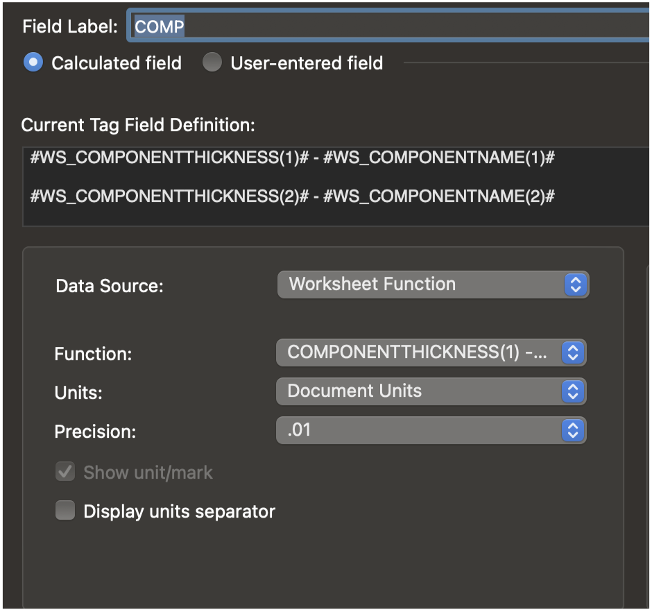
#WS_IF(ComponentName(1)='', '', Concat(ComponentThickness(1),' - ',ComponentName(1)))#
The above says that if the component name is an empty string [two single quotes next to each other] then return an empty string, otherwise return the Component Thickness and Component name separated by a space, a dash, and another space [what is inside the single quotes.
Note that inside the #WS_ # limiters everything has to be Worksheet format. You can't randomly mix and match Worksheet and Data Tag formats on the inside. In the data tag itself you can use both formats.
Pat,
Your formula works. Except it still reports back in decimal feet. I understand what your saying about setting them to inches in the dialog box. But that changes the formula and it no longer works. I cant figure out how to modify your formula to report back in inches or inches and feet
-
Thanks
I will need to look into the Data Vis deeper
-
Tom,
I like the ability to pull the material info from the wall
I started to use materials but backed off because I don't think you can use class overrides in viewports to control the look of the wall in plan
I have a wall I need to show both existing and new components. At 1/8" I don't want to see all the components and at larger scale
If i view the detail level at "low" to component disappear but then I cant see what is new and what is existing
-
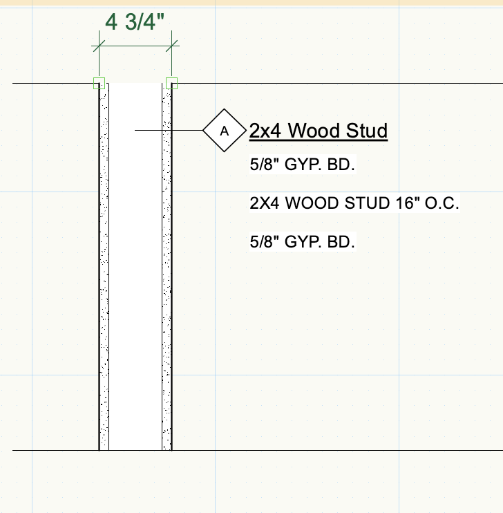
Pat
This is really really great
I can get the name of the component as I have it in the wall style
(I included the thickness in the in the component name - but it would be better if it took the thickness directly from the wall style data)
There is a component thickness text but its not doing what I expect.
any thoughts on how to have the actual thickness as part of the tag?
-
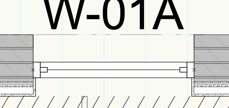
I would like to have a data tag that would report components of a wallI
The tag I made reports the description (I listed the components in the description) but this means i have to manually input info that is already part of the wall
There must be a way to pull the component "Name" and "Size" that is all-ready part of the wall type
how can I get this info into a data tag?
-
Unless you can use Tags on referenced projects/objects the you are forced to pick on or the other when you start a project.
Tags are to awesome so good bye referencing project sheets, hello incredibly large documents.


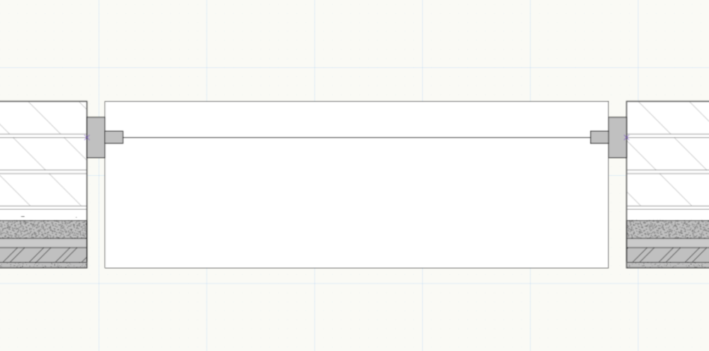
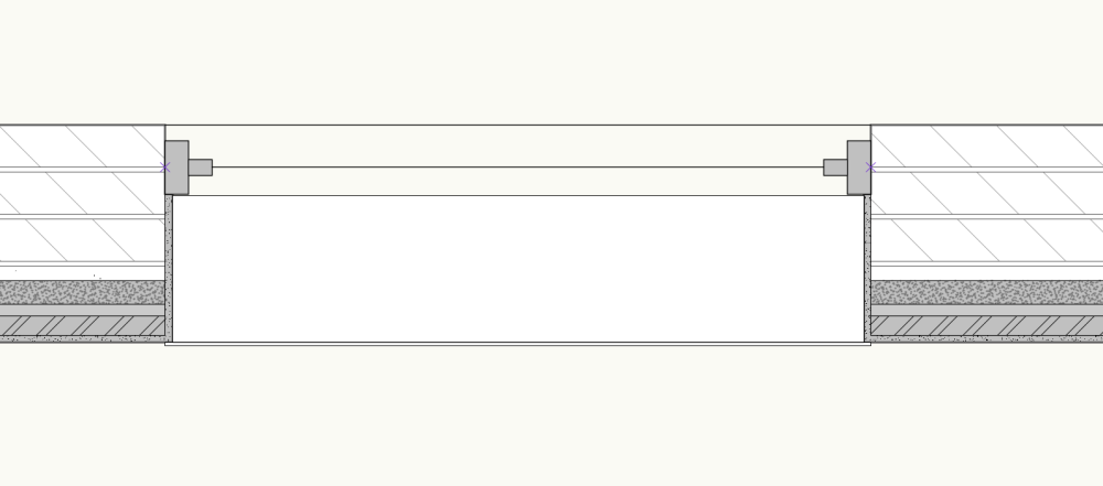
Window Sills, windows and wall Closures
in General Discussion
Posted
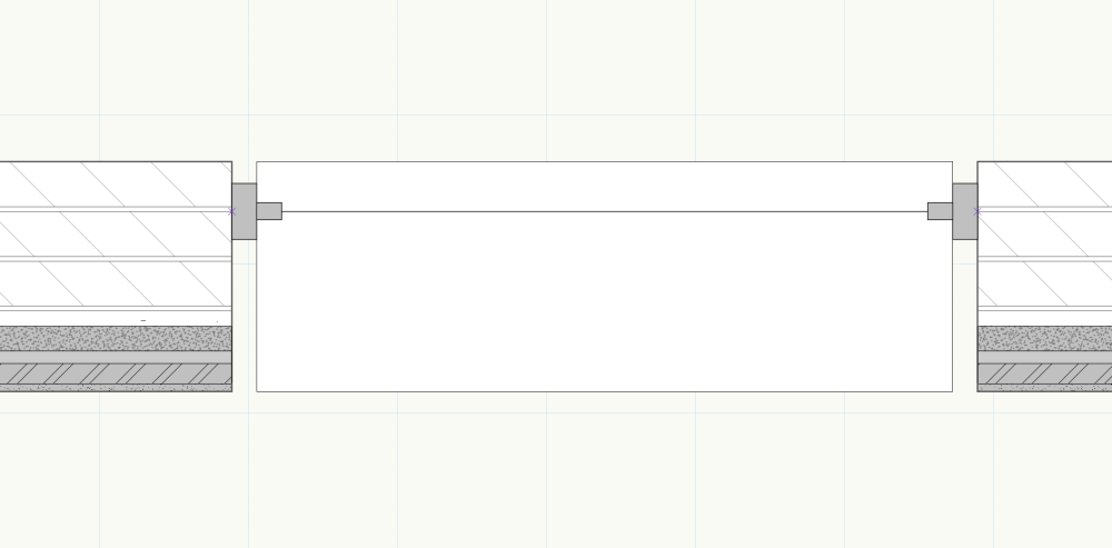
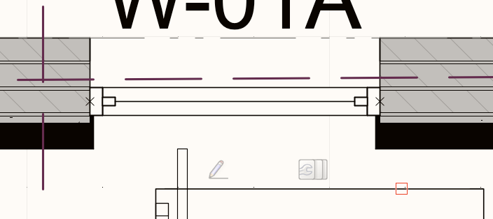
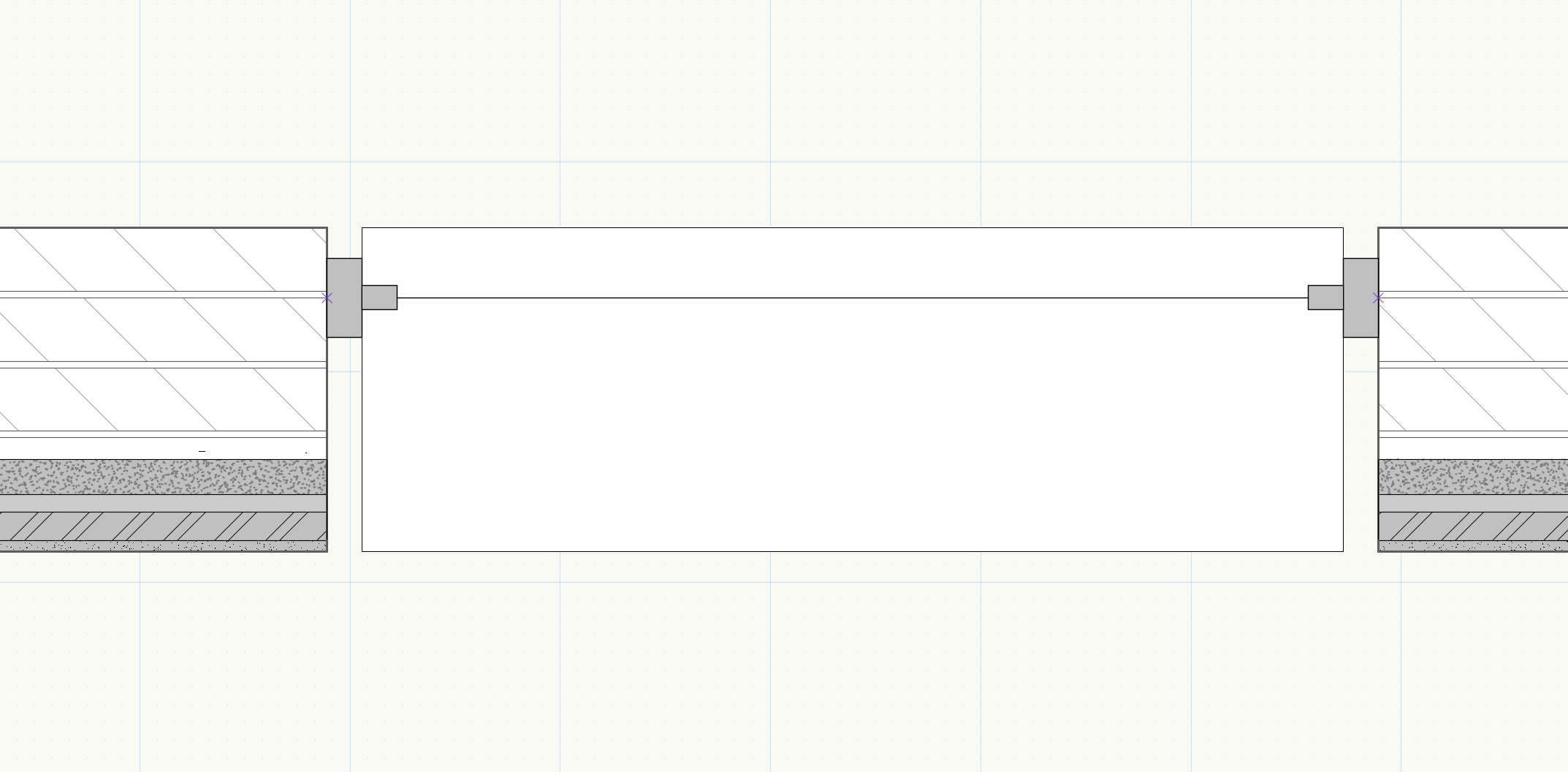
We have set up our window styles and wall closure so the window are in the correct location automatically. However when I add window sills to the mix, the sill is in the wrong position. they are offset from the correct faces of the window frame
it seems the window sills are set up to understand the the center of the window frame and the center of the wall, so when you set your windows to insert of another position other than the "center" it throws off the sill. I really never understood how to control sills so perhaps I am missing something.
it seem like the sills are not yet compatible with the new wall and window insertions controls.
It would be great to have a detailed video walking through several condition combining sill types, window styles, wall styles with several components set up with wall closures showing how you can place a window exactly where you want it to go relative the the wall components.
and or a working file with examples that really cover some real world examples
Thank you