


Hammerhead
-
Posts
18 -
Joined
-
Last visited
Content Type
Profiles
Forums
Events
Articles
Marionette
Store
Everything posted by Hammerhead
-
Thanks Alan!
-
Any place to get a 2D/3D hot tub?
-
There is a sloped window option, but as far as I can tell only the top of the window slopes. Is there a way to slope both the head and the sill of the window? In the attached file, the windows would go in the wall above the gable roof and below the shed roof. Thanks in advance for any help you can provide!
-
Hey Guys. I backed up and used a pad with grade limits without using the contours mode and got the results I was looking for. Thanks again for all the help!
-
Thanks guys, and thanks for your comments Benson! I have learned a bunch in pulling this project together and wouldn't have gotten this far without everyone's help in the community board forum! I go back way back to the Minicad days and am finally designing in the way the program was intended, in 3D! I will give your thoughts a try tomorrow, but in the meantime attached is another screen shot showing more of my project...
-
In the attached scan you will see green highlighted existing contour lines. The red contour lines are the new contours, the green contour lines are the old (existing) contour lines that should go away when updating, but are not. There should not be multiple contour lines at the same elevation. Bottom line, we need to get rid of the contour lines shown in green.
-
I did not build a pad, or set grade limits as I am simply building a stepped foundation matching the existing contours. Is there something in the programming VW that requires me to set a grade limit before I can modify contours ending up with only the modified contour line without keeping the section of existing contour line? No error messages. BTW, although the bottom of the page shows SST-Issue 1506, I actually pulled your instructions from SST-Issue 1507 starting on page 24. Thanks!
-
I am trying to modify my site plan to show new contours to work with my building plan. I followed Jonathan Pickup's SST-Issue 1506 unfortunately without success. The original section of existing contour line between the ends of the new (red) contour line remains in place after updating giving me wonky results in 3D. In Jonathan's example the existing lines go away after updating. The techs at VW do not seem to have an answer for me. Any thoughts out there. I have attached both a 2D and a 3D drawing to help explain my situation. Thanks as always for the help!
-
Hello Again Jim, Well, with a bit more effort I was able to get your solution to work using the extract tool then the fit walls to objects command. Thanks!
-
Hi Jim, I believe I tried that with Alexander over the phone with no luck. I sent the file to Alexander last week and he was puzzled and was going to consult with other techs. Would you kindly check in with Alexander to have a look at my file to see if we can hash through this. Thanks!
-
Jim, I used the stepped wall command to draw the foundation walls and tried using the "fit walls to object" option, but with no success. Thanks for the thoughts. Any others?
-
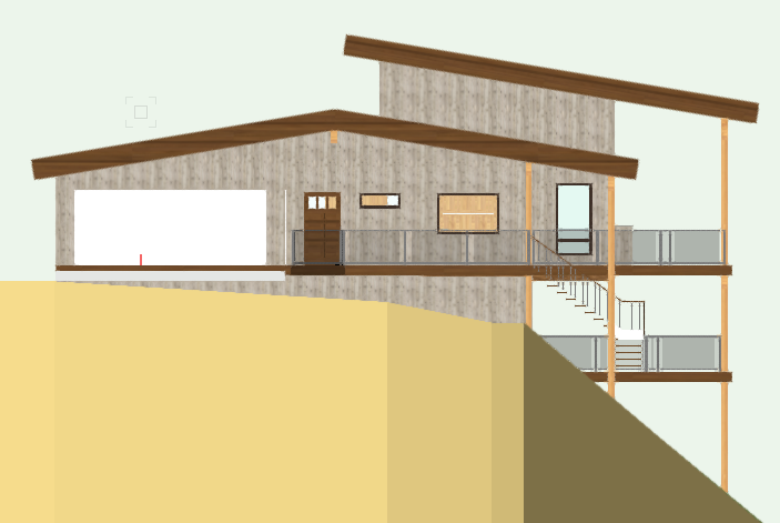
Hello All, I spoke with a tech at Vectorworks about how I could stretch the lower floor walls of my project, at least the siding anyway, down to the stepped foundation below and he could not come up with a solution. He was to reach out to other techs and I have not heard back. Does anyone out there have a suggestion about how I can stretch the gray siding of the lower elevation down to the stepped foundation shown in the attached photo? I will likely build the project with the bottom of the siding not stepped but following the grade in a straight line on each of the four elevations, so showing it this way in the drawing would be best, but if it is easier to somehow have the siding follow the stepped foundation in the design I am OK with this. Thanks in advance as always!
-
That did it, thanks Benson, and others!
-
Bingo! Thanks Benson. I actually tried using the Split Tool, but must have not been using it properly. Is there a way to now join all of the pieces of the extrude now that I have deleted the parts that I don't want so that I don't see the lines between the extrudes when rendering?
-
Thanks Jonathan. BTW, I subscribe to Archoncad. I am not understanding your suggestion. What exactly do you mean by "create the clipping solid objects"? I can't figure out how to turn the extrude (radiused roof) into several solid objects which might be what you are suggesting. I have tried creating a rectangle over the extrude (radiused roof) then "Clip Surface" but I get an "illegal object(s) selected" message. I have also tried using the clip tool on the extrude (radiused roof) and although I see the clipping rectangle being drawn nothing happens. Further thoughts/suggestions?
-
Hello All, Does anyone know if there is a way to clip an extrude, or might you have a suggestion about how I could remove a section of radiused roof. In the attachment you will see there is a lower radiused roof and an upper raised roof. I need to remove not only a section of the lower radiused roof under the upper roof, but a few other areas as well. I am hoping I don't have to draw several sections of lower roof then combine them. Thanks in advance for any advice you might be able to provide!
-
Thanks Zoomer!
-
Hello All, I have owned VW for many years and I hate to admit it but I have really only used it 2 dimensionally. I am currently working on a design for my own home and have decided I should learn to use the program as intended. Anyway, I am currently doing some modeling of the home on the site. The roof is radiused and I am trying to figure out how to do draw walls that have radiused tops to complete the model. I am guessing there is an easy way to do this but haven't sorted out how. Any help would be greatly appreciated! Attached ( I hope) is a screen shot showing the home without the radiused top wall. Thanks!