pbat
-
Posts
14 -
Joined
-
Last visited
Content Type
Profiles
Forums
Events
Articles
Marionette
Store
Everything posted by pbat
-
Add plan guides to doors that do not affect wall opening
pbat replied to pbat's topic in Architecture
Andy, That worked! Thanks so much for that information. My screen grab was of me doing a very quick diagram in plan around a door in a wall. I had prepared a unique plan symbol with all the info needed. Once I added the loci, it worked perfectly! Thanks! -
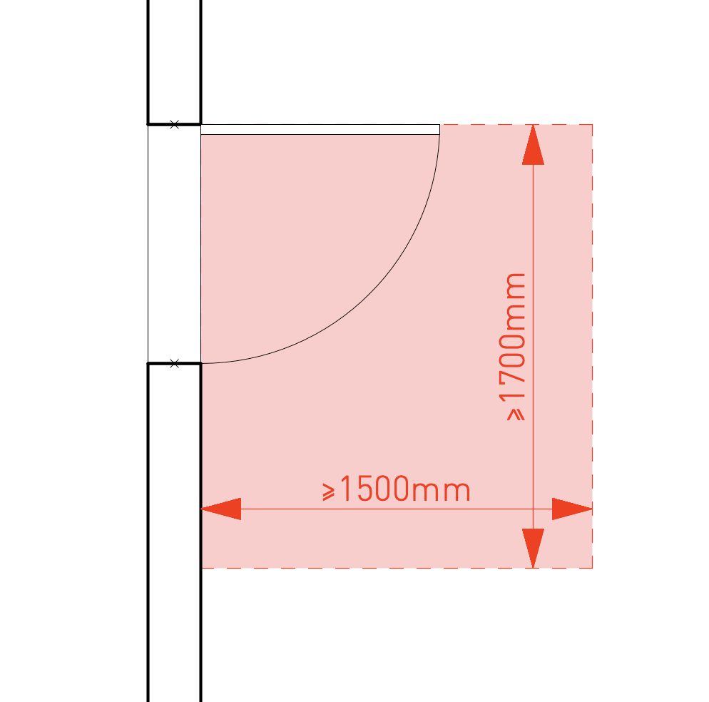
I am looking to add some building code minimum distance requirements on either side of a specific door type. It is a door that is commonly used at the entry of units within a multi-family development [see the screen shot below]. I would like to add them on a class that can be turned on at any time to quickly verify that all doors meet code requirements. It seems to me the only way to do this, would be to make our own custom hybrid symbol and then place it within the "use symbol geometry" in the door tool. However, I am struggling to do that without affecting the 'opening' on the wall. Is there a way to add 2D lines or rectangles with text on the plan view of the hybrid symbol in a way that doesn't affect how the wall is cut when inserting the door in?
-
Thanks Jeff. I think you are correct, but I was hoping someone had found a way around it.
-
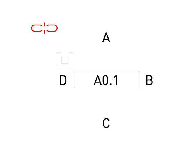
We are just moving into VW 2021 from 2019 and looking to maximize the potential of smart markers. As part of that we are customizing all markers to fit our office standard. I am having a hard time customizing the interior elevation marker to the graphic layout we would like. It looks like the interior elevation markers are designed to all be square or at least for the drawing number reference to be equally spaced from the centre point of the marker. Our office interior elevation marker is rectangular [see screen shot below]. Does anyone know if it is possible to adjust where the 'A' and 'C' reference text are located in relation to rectangular box with the sheet information? Thanks,
-
A project sharing file that has been working properly over the last few months is having doors, wall data tags, and symbols in the resource browser randomly disappear. The file was cleaned up and purged to streamline speed of work and ensure office graphic standards are being used about a month and a half ago. Yesterday, the computer of one of the team members had an issue connecting with the server while their local project file was actively being worked on. The office server had to be restarted for the computer to be able to reconnect to the server. Right after that, the same user started having odd things happen on the file. First, all the resources/symbols on the resource browser disappeared. The resources/symbols were still present and editable in the actual drawing but the resource browser was empty. To resolve this, the local user file was deleted and a new one opened from the master file on the server. That resolved the resource browser issues. At the end of the day that person saved and committed their work. This morning that same person pulled a new local/user file from the server and replaced the one that was used yesterday. Halfway through this morning, the doors, which are made with the door tool and have a custom style disappeared from some but not walls. The walls had an opening showing but no doors [we double checked and it was not a class visibility issue]. We tried adding a door on the wall to see if that refreshed the wall. That made all the openings on the walls heal and close. We had to add new doors and data tags. A similar problem is also happening with data tag on walls. Some wall tags are disappearing randomly or shrink to be so small they can't be seen. All these problems were limited to the computer that had the server problem until this afternoon, when it started to show up in other local files of other team members. If the master file is opened on computers that have never opened the file, the local file displays everything correctly, even if that same files shows up incorrectly on the computers that have been working on that file for a few months. Are these common/known issues? Could this be a result of a corrupted file due to the server issues yesterday. If it is related to a corrupted file, is there a way to fix the corruption or issues without starting a new file from scratch? Starting a new file is super inefficient and time consuming. My biggest concern is on making sure this does not come back later on when there is much more information on the file or when there is a push for a deadline. I don't think this has any effect on the file, but we do not use a full BIM system. The only 3d objects used are walls, doors and windows. The rest of the drawings are in 2D. I hope someone can help Thanks!!
-
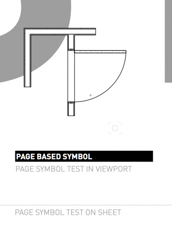
BUG: Page Based Symbols with Navigation Graphics
pbat replied to John Meunier's question in Troubleshooting
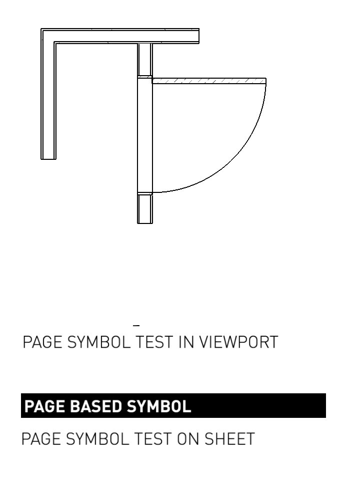
I am having the same issue with page-based symbols in viewports when using VW2019. The page-based symbols work properly when the 'Navigation Graphics' setting is set to 'Good Performance and Compatibility'. When that is changed to 'Best Performance' the page-based symbols seem to be scaled down inside the viewport. In the image below the page-based symbol should be the same size on the sheet and in the viewport, but in the viewport you can see it super small just above the 'T' in 'test'. The page-based symbols on the sheet super scale up when you work in annotation space. In the images below, the grayed out text and line are the page-based symbol on the sheet. Has this been fixed in the service pack 1? Our updates keep failing for that as well.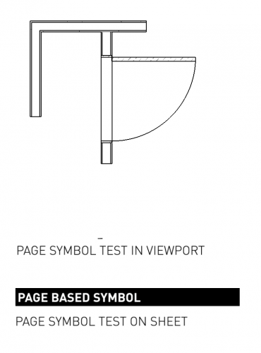

-
At the office we have made custom symbols for the room names, grids, sections, etc. All of these symbols have been made as page-based symbols so that their size is the same regardless of the viewport scale. That way the annotation symbols in a detail at 2" = 1'-0" and a floor plan at 1/4" = 1'-0" are the same size. This is creating issues when the sheets are exported as DWG. The page-based symbols exports super small in the DWG file. If seems that the page-based symbols are not being scaled with the rest of the drawing to a 1:1 scale. This has become an issue with sending CAD files to consultants because all the grids, section markers, room labels, detail bubbles, etc. are all too small to see in their cad drawings. Is there something that can be done to avoid this? We are working on VW2017SP5. Thanks,
-
I found a work around where I adjusted the one of the standards symbol in the ID_Symbol.vwx file. This allowed me to control the visuals of the symbol and font. Then once I placed one into the file. I edited it through the individual file resource browser. There I made it a page based symbol and re-scaled it to be the right size. Now I have a custom wall tag that is in the office template file and is the same size in all drawing scales. I am not sure that is how it is supposed to work, but it got me what I wanted.
-
I drew the symbol in the same file that the standard ID label symbols are drawn in - 'applications/VectorWorks 2017/Plug-ins/Common/Data/ID_Symbols.vwx' . Is what you mean by the correct library file?
-
Does anyone know how to make a custom wall ID label work? I followed the steps on the VectorWorks Help [ http://app-help.vectorworks.net/2017/eng/index.htm#t=VW2017_Guide%2FAnnotation%2FCreating_Custom_ID_Label_Symbols.htm&rhsearch=Id label&rhhlterm=Id label&rhsyns= ] but when I go to my file and use the ID Label tool the new ID label symbol does not show up under the ID Style drop down menu. I have tried multiple times, restarted VectorWorks, but it still doesn't show up. Also the symbols scale up in viewports at different scales. Is there a way to make the ID labels act like a page based symbols instead of world based symbols so they remain the same size at different scaled viewports? Any help would be great. Thanks!
-
I would also like to know if there is a way to create custom drawing labels that have the same capabilities as the standard drawing labels.
-
I am looking for an answer to the same question. Has anyone figured out a way to do this, or will I have to look into writing a script to accomplish this.
-
Thanks Pat. I will try this out.
-
I have made a series of custom door symbols with a record format that includes door no., dim, material, type, etc. on it. When I create a worksheet report, it shows four symbols on the worksheet for ever symbol on the drawings. Each of the repeated symbols have the exact same data. I could hide the extra instances by using the sum command, but I would like to know/understand what is going on. I have tested the symbols and worksheets on an empty file and it works find there. Any idea what is making the worksheet show extra datal? Thanks in advance, pB