Steven Kenzer
-
Posts
241 -
Joined
-
Last visited
Content Type
Profiles
Forums
Events
Articles
Marionette
Store
Everything posted by Steven Kenzer
-
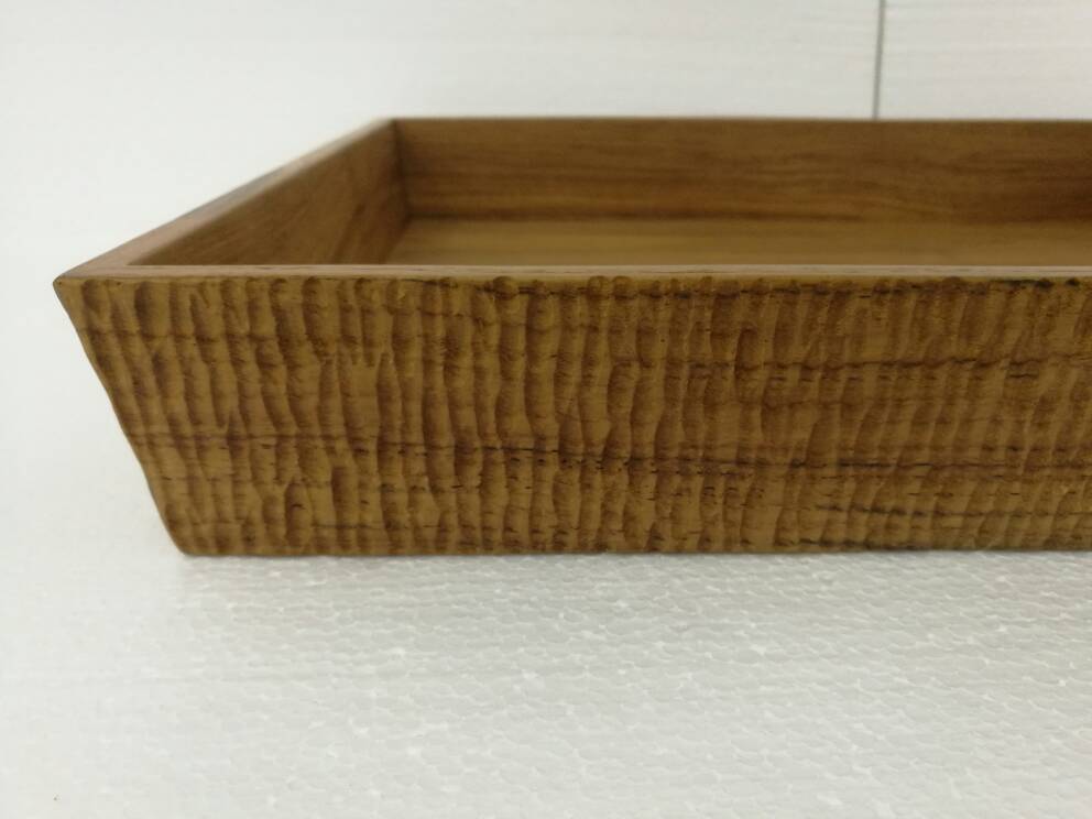
I need to create a 3D solid object that looks something like the attached 2d screen shot. I'm trying to create the carved texture you see on the image attached by taking that object and then subtracting from a solid one. I can easily extrude a free form shape but that ends up straight along it's path. I need that path to be irregular also. Maybe I’m going about this totally wrong...this is a bit out of my wheelhouse. Does anyone have any thoughts on this? Perhaps a different approach or one that gives me the solid object I'm trying to create? Ultimately, I don't have to duplicate the image exactly but just convey a somewhat similar hand carved look to the surface. Thanks in advance for any help here...always appreciated.

-

Extrude along path.....need help
Steven Kenzer replied to Steven Kenzer's topic in General Discussion
That's a good point...thanks. It does seem simpler to change path with Sweep than EAP. I'm back on track now. -
Extrude along path.....need help
Steven Kenzer replied to Steven Kenzer's topic in General Discussion
Great to know......thanks again. -
Extrude along path.....need help
Steven Kenzer replied to Steven Kenzer's topic in General Discussion
The beauty of this forum. Yup, that was it! The other day, I was curious about that setting, so switched it on. Unfortunately, forgot to turn it off. Thanks so much everyone. -
Extrude along path.....need help
Steven Kenzer replied to Steven Kenzer's topic in General Discussion
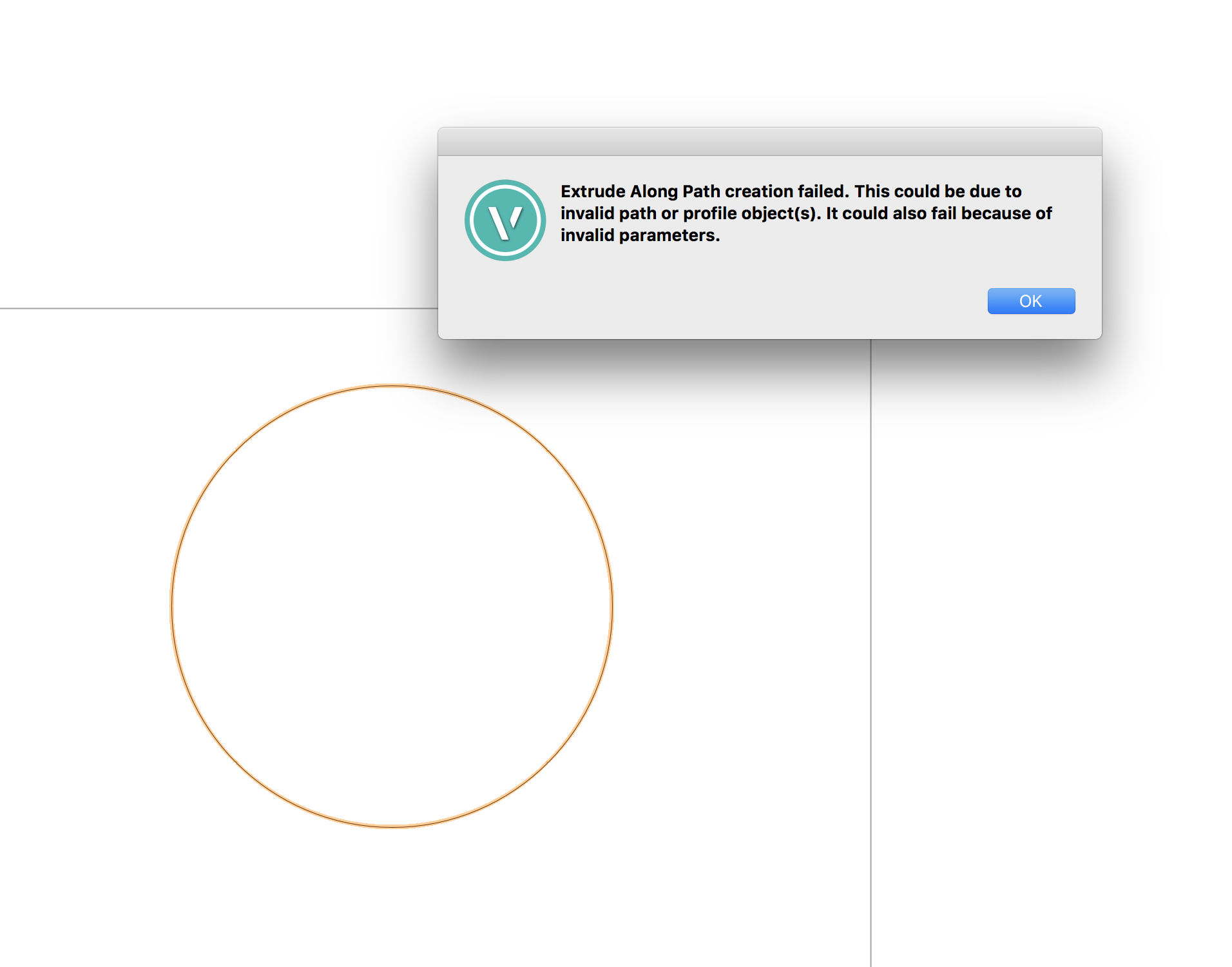
Thanks, Pat. Yes, I've never been concerned about the location of the profile before. Having said that, I just opened a new blank file, plan view, placed one circle in, then placed a smaller circle in. Selected both and used the larger circle as the path, smaller one as profile and.....failed once again! See screenshots. I'm starting to wonder if this is some malfunction of VW for some weird reason. Is it possible something is corrupt here??


-
Extrude along path.....need help
Steven Kenzer replied to Steven Kenzer's topic in General Discussion
Sweep + loci worked well...thank you! Jim, I'm still not able to do this as I typically did and as you showed doing it??? No clue why that isn’t working. I am on 2017 SP3. No need to convert these 3d circles for that process, correct? You drew a large circle, then drew the smaller one, placed profile circle where you said and it worked. I go through that same process and it fails. I was never aware the location of the profile made a difference. Baffled but all good with Sweep command for now. I'm going to keep playing with this to see what I'm doing wrong in terms of Jim's technique. Thank you all. -
I'm having trouble with a very simple extrude along path command. Here's the task. I need to run a 1/2" diameter rod around a 36" diameter circle. Sounds simple, I know but..everything I've tried fails. I first create the 36" D circle, the path. Am I correct I need to convert that to a polyline? Then I draw a 1/2" diameter circle, the profile. Do I need to convert that profile circle to something other than what it is? I've tried all kinds of combinations to no avail....all fail to create the object I need. If someone could help me out here, I would be most appreciative. What's crazy is I've done this on many occasions before...can you say "Senior Moment"? :-) Thanks everyone.
-
Ha! That was it! Thank you!
-
Out of the blue, my Navigation Palette is empty. It remains empty no matter what layer I'm in and no matter what drawing I'm in. I must have triggered this somehow but honestly, I have no clue. Does anyone know why this would suddenly happen?? Thanks in advance for any help.
-
I'm getting ready to pull the trigger on a new 15" MacBook Pro and wondering if the forum could help me in terms of what upgrades are worthwhile to this laptop. . I'm currently running 2017 on a new 27" "souped up" iMac and all is well on that end. I would be adding a display to the MacBook Pro, perhaps the LG 4K although wondering about other recommendations for the secondary display. This is not for heavy architectural work but complex furniture design, 3d and 2d. I'm currently looking at: 2.7GHz quad core Intel Core i7 processor/Turbo Boost up to 3.8GHz. Would I noticeably benefit from the $200 upgrade on the processor 2.9GHz/3.8GHz? Radeon Pro 455 with 2gb memory. How much of a difference to go to the $100 upgrade to the Radeon Pro 469 with 4gb memory? Any issues I should be aware of with this laptop in terms of interacting with 2017? Is its limit of 16 MB of ram an issue for anyone? Thanks in advance for any help/advice on this subject.
-
Trackpad, which I don't normally use, works fine. Not one issue of that "edit extrude" window opening on a single click. When I went back to my Logitech Performance MX, it did it again.....must be a mouse hardware issue. I never considered that. The mouse is several years old so guess it's time for a new one. Thanks, Jim.
-
Interesting thought, Jim.....I'll check that out and let you know.
-
When I'm working in a 3d model, furniture in my case, I've been finding that a single mouse click on an element will randomly open the "Edit Extrude" window. Shouldn't this be brought forward by a double mouse click? I can single click various elements in a drawing without the "edit extrude" window opening but then, when I single click another random element, the edit extrude window opens. I believe this started with 2017 and wondering if there's a preference or other setting that I need to change. I've checked my mouse preferences, VW preferences, document preferences, etc....can't find anything related to this. What am I missing here?
-
My Selection Tool Marquee boundary line is no longer visible after recent update. It still selects what I'm after but it would be nice to see the boundary line as it does. Is this a simple matter of some preference needing to be checked, or something like that? I've looked and looked to no avail. Thanks.
-
Just updated to SP1 2016. Does this resolve issues with El Capitan? I haven't updated my OS to that yet but would like to. Jim, are you giving the "green light" to move forward on EC/2016 now? Thanks.
-
Thanks for the link...and advice. Yes, I think I'll hold tight for awhile before El Capitan update. Just not worth dealing with VW issues.
-
I haven't upgraded yet to El Capitan because of issues mentioned here. But, I am wondering, when one refers to older HP plotters, just how far back one has to go to be concerned. I have an HP Designjet 510. Will that model be affected by upgrade to El Capitan? No issues with it on VW 2015/2016/Yosemite. Thanks.
-
Yup, not exactly a powerhouse machine but really has treated me well and been fine for several years. An upgrade does approach though. Thanks for your time.
-
Interesting, Jim. After rebooting my computer, things are moving smoothly again. I guess it just needed to get it's "life" in order after downloading. Thanks.
-
Thanks, Jim..will send shortly.
-
Has anyone noticed a sluggish behavior to 2016? I'm having some issues. Not terrible but enough to frustrate me. When I pan, there's a micro delay. Dimensioning and lines also seem to be slightly delayed. I'm wondering if the specs on my computer are now starting to take a hit with the new release. Maybe there's a setting I'm needing to turn off? No issues with 2015. Jim, might that be the case, that it's time for a new computer? Thanks.
-
Thanks, Tim. I'll check out that technique, as well.
-
I think I just answered my own question via Vectorworks Help: "If objects seem to be the wrong physical size after import, ensure that the units chosen are correct. (Model Space Scale only affects the display, but Units Setting in File affects the actual measured size of the objects.) DXF/DWG or DWF files do not always have the true units set, and sometimes have incorrect units set. The Vectorworks program guesses the units based on the information available, and indicates what it found in the dynamic text at the top of the pane. If the guess is wrong, set the units manually. If you do not know the correct units, but you know the true length of one of the objects in the drawing, determine the true units as follows. Import the file and choose Custom units, setting the edit boxes to something like 1 DXF Units = 1". After import, measure the size of the object that you know the true length of. Close the document and redo the import, but this time set the units to Custom with these values in the edit boxes: (measured length) DXF Units = (true length). For example, if the true length is 1", but the measured length is 2.54", enter 2.54 DXF Units = 1". (Do not include units in the first box, and if in feet and inches mode, just use the total measured length in inches.) If the Vectorworks program finds an exact match for that ratio, it will change the Custom choice to the correct units. (In the example above, it changes it to Centimeters.) If the measurements and the ratio are not exact (for example, 2.539 instead of 2.54), manually adjust it to a standard ratio. Common ratios have values such as 1, 12, 2.54, and powers of 10. Examples: 1/12, 12/10, 2.54/0.01, etc. If you do not know any true lengths, but the document contains dimension objects that show lengths, follow the steps just described with the following change: Select Convert Dimensions to Groups (see Import Options: Objects Tab), import, and use the value in the imported dimension object as the true length."
-
Hi, All. I'm trying to figure out why a dxf file I'm importing is showing up with bizarre dimensions. For example, a room that should be about 14' wide, dimensions out as some absurd number, like 250' wide. This is a 3D model I'm supposed to do a 2D shop drawing for, so I need to read all dimensions accurately, of course.. It's coming from an office that uses CadWorks..all pc, I'm on a Mac, not that that should matter. I've played around with the importing options but seems, no matter what I try, this behavior remains. Are their certain import options I need to pay very special attention to here? Do I need to know what the scale the designer used on the 3D model is and match that on my import or, can I import to "fit the page" or "this scale" and select any scale I want? Is "Determine Automatically" to be selected or not? Should "Set Vectorworks Units to Match" be selected? Any help here would be greatly appreciated. Thanks.
-
Thanks, Alan......helpful video, for sure.