


taavilooke
-
Posts
41 -
Joined
-
Last visited
Content Type
Profiles
Forums
Events
Articles
Marionette
Store
Posts posted by taavilooke
-
-
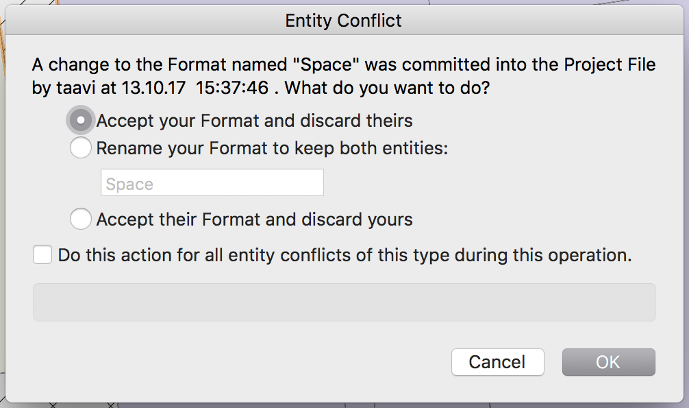
Here is the dialog I was talking about. If the other users accept this change, the spaces become uneditable. As far as I know, I have not changed any formats, whatever this is.
-
Hi!
There's a weird problem with space elements: every once in a while they become uneditable (like the one that is selected on the screenshot)-- instead of the normal OIP for a space it shows only a few fields for the element and the boundaries of the space cannot be changed any more. Sometimes it helps to restart VW or create a new working file from the project file. However other times the spaces stay like this and the only way to change them back to normal, is to delete the space and crate a new one.
Has this happened to anyone else? What could be causing this?
We are working on VW 2017 SP4 with project sharing.
Regards
Taavi
-
Hi!
I'm working in a Project Sharing file and trying to export to IFC. It seems that the data that is entered into the Export IFC Project dialog will only stay in the same working file that it is in. Even when I also commit the setting to the project file, it does not show up in the other working files or in new working files created from the master.
Does anyone have experience how to save the IFC Export Setting to the Project Sharing master file?
Regards,
Taavi
-
Oh well, you've got my vote on this.
As a sidenote, this WinDoor looks like a really good plugin, it's a pity they only sell it down south.
-
 1
1
-
-
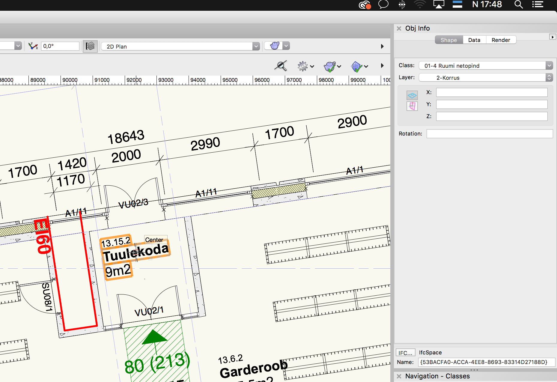
Is it possible to replace the window and door ID labels with custom ones, that would display some additional information from the data attached to the elements (e.g. the dimensions or fire resistance)? It would be really useful, but I haven't found any reasonable way to do this. The ID label tools seems to be the right tool, but it still only allows displaying the 3 ID parameters just like the window element itself.
Regards,
Taavi
-
Hi!
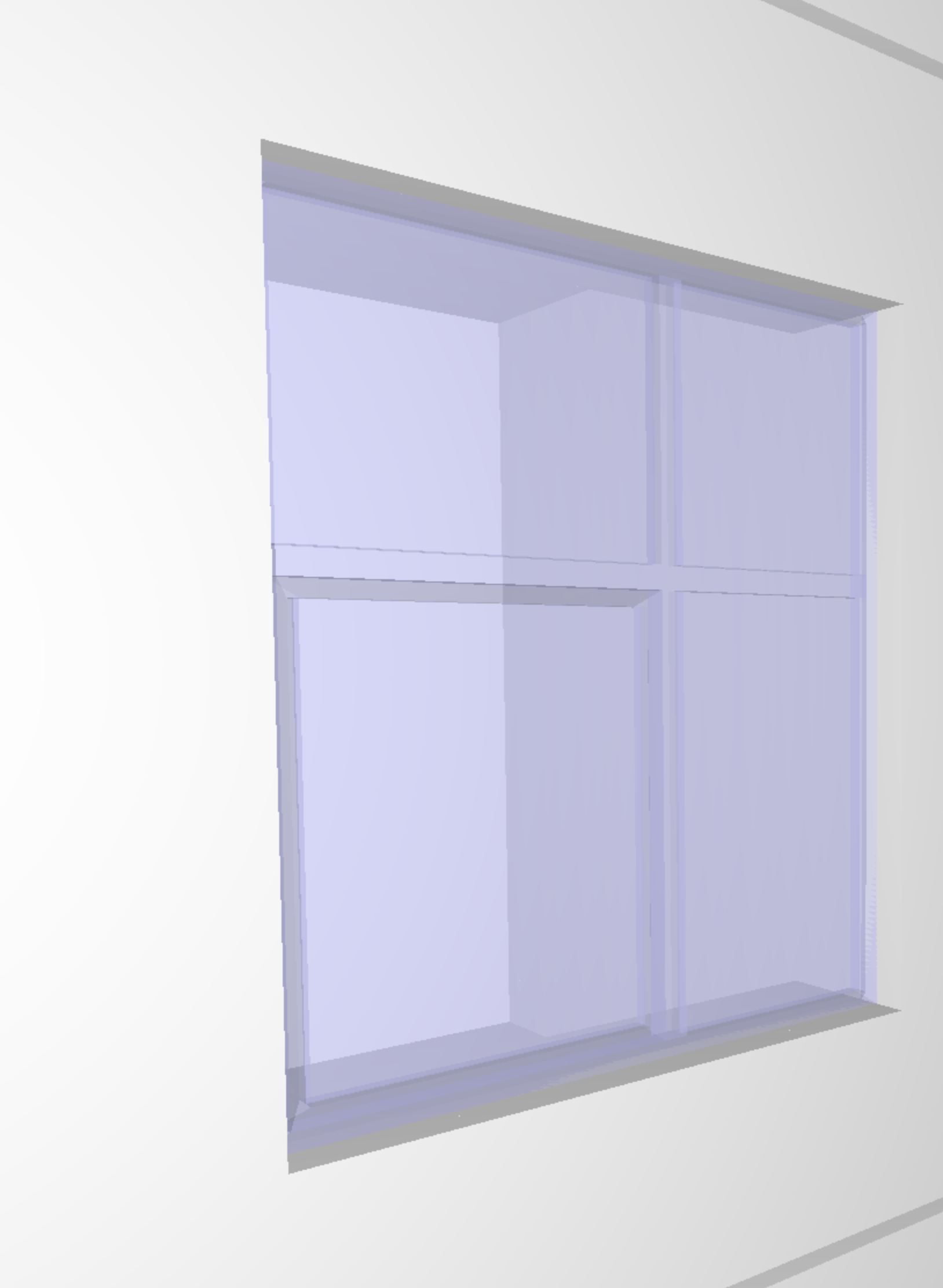
The geometry and textures of windows are wrong when I export the model from VW 2017 to IFC 2x3 CV 2.0. The frame of the window is transparent and the faces of the jamb and sash are intersecting. I've attached a screenshot of what the window looks like in Solibri. What could be causing this and how do I fix it?
Thanks,
Taavi
-
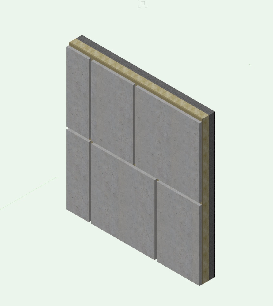
Hi!
I'm trying to create a wall that has vertical and horizontal joints (essentially just the outermost layer of concrete removed). I've attached a picture of what I'm trying to achieve. At the moment I'm creating the horizontal joints by lowering the top bound of the outer layer in the wall definition, and the vertical joints by creating wall recesses. However there is a problem that these recesses do not export to IFC.
Using a symbol seems reasonable considering that the wall has about 1000 of these joints. However I cannot make a symbol of the recess itself and I cannot make a recess with a 2d symbol (rectangle). I can only make a recess with a symbol that is a box and in that specific case it does not show up in IFC. Why could that be? Is it a bug? Are there any other ways to create these joints?
Regards,
Taavi
-
Sorry for replying so late, I didn't have time to look into it before the summer break.
Thanks Pat, this script worked perfectly. I modified it slightly so that it also displays the current value next the field names and types: https://pastebin.com/Dq0baJmH. It makes it a bit easier to understand which field is which. With these field names it was really easy to create a worksheet that displays and changes all the custom sash options.
For future reference, these fields mostly control the custom sash options:
'Window'.'Cols' & 'Window'.'Rows' -> the columns and rows
'Window'.'CustSashWdth' & Window'.'CustSashHght' -> semicolon separated list of widths and heights of the openings between the sashes
Window'.'CustSashOp' -> semicolon separated list of integers indicating the window opening type
Window'.'CustMullWidth' & 'Window'.'CustMullDepth' -> mullion dimensions
-
I'll try to explain the situation a bit more:
I have already created all the windows in the model with the correct rough opening sizes. Now I have to specify how they are divided up into panes. Style-wise they are all the same style, just that the dimensions and sash patterns are different. The tricky part is that almost none of the windows will have the same sash-panel patterns. I'm hoping I can specify the sash pattern through some code and then make Marinonette (or vectorscript/python) set the custom sash options for all the windows. Styling all the 500 windows manually will be a headache...
-
Hi!
I have a project where I have to create about 500 windows with custom sash options (multiple panels, some operable-openable, others fixed). There are reasonable constraints like the operable parts being the same width everywhere. This seems like a perfect place for using Marionette to set all the custom sash options according to some pattern from a record or sth similar.
Is there a way to access the custom sash options of windows inside a marionette script? Looking through all the nodes, I cannot find anything for this purpose. The Vectorscript/Python reference does not give me much either.
Regards,
Taavi
-
In a sense a large part of designing in BIM is assigning styles to objects, i.e. declaring that these objects are of one specific type and have the same properties. When the properties of this style are changed, all the objects, that this style is assigned to, should change as well. I have been trying to wrap my head around the system that Vectorworks has to make styled objects, but so far it does not make much sense. Below I'll outline how I understand it so far. I also tried to put then into a hierarchy and attached an image of this. Is that roughly correct? Is there some intentional logic underlying this system, or is it mostly just contingent, in the sense that these features have been added incrementally and Nemetschek hasn't taken the time to redesign them in an intentional way? Are there plans to update this system? The way this works in Revit for example, makes a lot more sense.
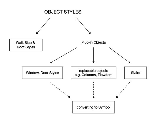
There seem to be only 2 real "object styles" (shown on the image below as well):
Wall, Slab, Roof styles - these work exactly how one would except styles to work
Door, Windows styles - essentially work like styles as well, but are grouped under plug-in objects for some reason.
Everything else only works as replaceable plug-in objects. In the OIP these have the save element and replace element buttons. However all of these objects have to replaced manually to reflect the changes, that have been made to the style, which will get complicated on larger projects with lots of elements that have to be changed.
Stair seem to be different from other plug-in objects. There's a button to save an existing stair as a style, which can be placed in the model, but it works the same way as the rest of plug-in object (updates to the style are not reflected in the object instances). However I cannot find a way to replace an existing stair with another saved style. Hence I have to make changes to stairs individually to every instance. Correct me on this if I'm wrong.
All the plug-in object can be turned into symbols, of course. This only works for objects that are not height parametric, e.g. columns can have a different height depending on the story they are on, in a symbol they can only have one specific height. Therefore this one only works for things like furniture.
Edit: Corrected the type in the image
-
Hi!
I'm working on a BIM project where I have an orthogonal building, but it is not facing exactly north-south. It makes sense to draw it so that the building axes are facing straight up-down and left-right. How can I export the model so that it is rotated to the right north-south direction (i.e. X axis pointing to north)?
Thanks,
Taavi
-
Looking into it a bit further, both of the properties (LoadBearing and BuildingEnvelope) seem to come from the IFC Data that is attached to the object (Select object > AEC > IFC Data) and I can change the value there to control what gets exported to the .ifc file.
Is there some way to control the IFC data for all these object through a report (or some other way) where I can assign the same data to many object at once? The idea would be to create a report for all walls in classWall-Interior for example and change the BuildingEnvelope to be true for all of them at once.
-
Hi!
I'm working on a BIM project, where I need to include metadata about the objects in the .ifc model. Does anyone have experience with the following metadata?
For walls/slabs/windows/doors, mark whether they are located in the building envelope or internally
In VW wall styles there is a place to define the building envelope (Edit Wall Style > Data > External), but window and door styles do not have this checkbox. When I review the .ifc model, VW seems to export this information-- model objects have a property BuildingEnvelope (true/false). However they do not always correspond what I have defined for the walls, it seems to be assigned autmatically by VW. How can I control this directly?
For walls, mark whether they are load-bearing or not
Inside VW wall styles there is a place for defining whether the wall is load-bearing (Edit Wall Style > Data > Load-Bearing checkbox) and the .ifc model has a property in Pset_WallCommon (LoadBearing). However these two do not correspond, even when I define a wall as non-load-bearing, it sometimes still marks the object LoadBearing=true. How can I controll this directly?
Thanks,
Taavi
-
In design work it is often necessary to model two (or three or however many) versions of a plan or some other project feature to compare them visually, present them to the supervisor or the client and then choose which one of them to go forward with. It seems however that Vectorworks is not built with this idea in mind, i.e. one model file is supposed to contain only one version of an object, not alternative versions of it. This often creates problems while working on project. Are there any recommended best practices how to organize the alternative designs?
These are the options I have gone through, but none of them really work:
- Splitting the alternatives into different files is possible, but cumbersome because it is complicated to compare the different alternatives to each other. Essentially they can only be compared by plotting and putting them side by side.
- Creating separate classes turns into a nightmare-- there will be way too many to handle.
- Creating separate design layers for the alternative designs seems like the best option. It becomes a hassle, if the alternatives need more that one design layer-- there will be 1-Plan-Alt_1, 2-Plan-Alt_1, 1-Plan-Alt_2, 2-Plan-Alt_2. Also, it is complicated to store these alternatives for later review, because layer organization soon becomes a mess with so many layers in there.
Theoretically it would be good to put all the alternatives into another file using the last option (creating separate design layers), with everything but the appropriate layer referenced into the file. This file can be archived and it will not clutter the layer organization of the up-to-date model, but it feels really hard to set up this file, especially if the model already has references, sheet layers etc. Is there a way to set this up fast? Are there some other options or VW features that I have missed?
Edit: Corrected some typos.
- Splitting the alternatives into different files is possible, but cumbersome because it is complicated to compare the different alternatives to each other. Essentially they can only be compared by plotting and putting them side by side.
IFC Export Setting in a Project Sharing file
in Architecture
Posted
It seems I managed to solve this problem. You have to convert the project file back into a regular VW document, make the changes to the IFC settings there and turn this file into a project file again. Then the IFC settings set in the regular document will always show up in the working files. Kind of tedious, but better than nothing.