


taavilooke
-
Posts
41 -
Joined
-
Last visited
Content Type
Profiles
Forums
Events
Articles
Marionette
Store
Posts posted by taavilooke
-
-
DomC's script does exactly what I need. That Marionette thing might actually be useful at one point. Thanks!
-
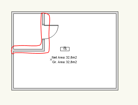
@Hans-Olav Well yes, but this creates spaces one room at a time. To get the area of the whole apartment with one space object, this one space has to encompass the whole apartment, right? But this one element doesn't know there are walls inside the space that it has to substract to get the net area (like the walls here).

-
Just now, Hans-Olav said:
@taavilooke I would use space objects to show area of apartments. We usually have three sets of spaces classed in three different classes, Net room, gross apartment and total floor area.
That would be nice approach. Is it possible to get the net apartment area (substracting the area of walls inside the apartment) with this approach automatically though? Drawing a space object with the perimeter walls of the apartment easily gets the gross area, but I can't find a way to substract the area of walls this way. Having to draw the space boundary manually would be a lot of hassle...
-
Ok, let me try.
Firstly, I have a worksheet like this that has all rooms summed up per apartment. Secondly, I have sheet layers with the plans of each apartment 1 through 12. What I would like to do is display the summed-up area of each apartment next to the plan. So the question is whether it's somehow possible to automatically look up the area from the worksheet and place that next onto the sheet layer as text?
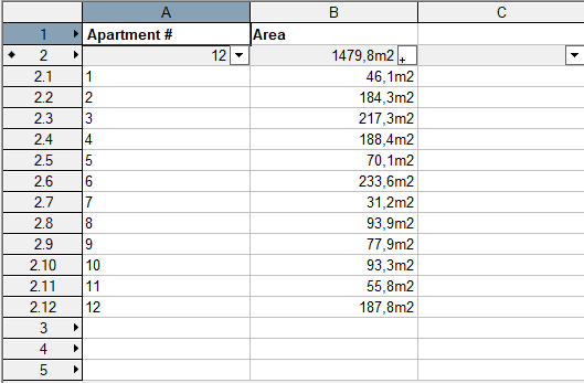
I mean I could always simply copy the values as text next to the plan, but it would be nice to keep that link automatic, so that when I update the plans, the area updates as well. Other way I could think of was to create a separate worksheet for each apartment and place that onto the sheet layer, but this seems like a lot of hassle to achieve something that should be easy to do.
-
Hi!
I'm drawing an apartment building and I need to set up a separate sheet layer for each apartment's plan with the area of that apartment displayed next to it. It's quite easy to set up a worksheet that sums up the area of each apartment (using Occupant Name for example). However in the worksheet all the areas are in one table. Is it possible to look up that corresponding value from the worksheet and display that separately from the other values?Thanks,
Taavi
-
Hi!
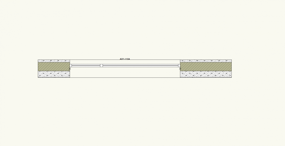
Is there any way to choose how custom sash windows are displayed in 2D plan view? I have windows with multiple columns and 2 rows of sashes and the openable sashes are always in the lower row. It seems that VW only displays the openable sashes in the upper row, in the example below the openable sash does not show up in the plan view at all.
Is there any way to fix that? I tried playing around with the options in the window setting and also the layer cut plane, but it did not change anything.
Thanks,
Taavi

-
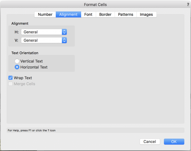
I got in touch with the local support and figured out a solution for one of the problems: It is possible to add line breaks to worksheets as carriage return characters ("\r") and they will show correctly if Wrap text checkbox is checked in the Format Cells dialog for this column.
Does anyone have recommendations about the hatches and world units? Is it possible to scale the hatches inside viewports in any way, to allow creating drawings in different scales?
-
 1
1
-
-
Thanks! That did the trick.
-
Hi!
I'm using scripts to write data into worksheet database cells with Runscript() function. Every time the worksheet is updated a dialog shows up that asks if the execution of the script should be allowed or blocked. I accidentally clicked on block all. Now the the dialog does not even show up and none of the scripts run in worksheets. How can I re-allow or unblock scripts to be run with Runscript() ?
Thanks,
Taavi
-
That was actually quite easy. This script will output all the wall or slab component names and widths to one cell. It is run with =RUNSCRIPT('ScriptName') in the worksheet header. There is a weird problem though: all the components are on one line when the worksheet is place on a sheet layer. Any thoughts how to fix that?
EDIT: the line wraps work if the line break character is "\r" and Wrap Text is check for this column. See the next post.
wallObj = vs.WSScript_GetObject()

(a, numComp) = vs.GetNumberOfComponents(wallObj)

comps = []

for x in range(1, numComp+1):
	name = vs.GetComponentName(wallObj, x)
	(a, thickness) = vs.GetComponentWidth(wallObj, x)
	comp = name + " " + str(thickness)
	comps.append(comp)

str = "\r".join(comps)
vs.WSScript_SetResStr(str)


-
2
-
-
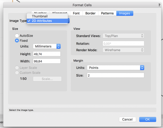
@JMRI actually figured out an even better way. In the Format Cells > Images dialog you can change the Image Type to Thumbnail. Then you get an image of the same length in the same scale for all the walls. It even works for slabs as well, you get a section of the style.
There is a weird problem though: the worksheets mess up the scale of the hatches that are set to page units. The hatches are way too small for the rest of the geometry. It seems to display these hatches as if they were in 1:1 scale. Does anyone have an idea how to change that?
For the component list, I'll try to create a better solution that would list all the components automatically in one cell.
-
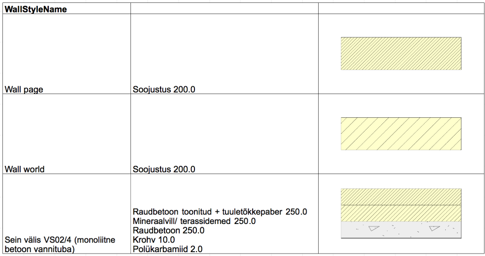
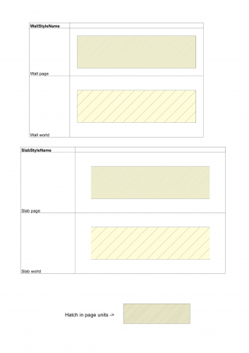
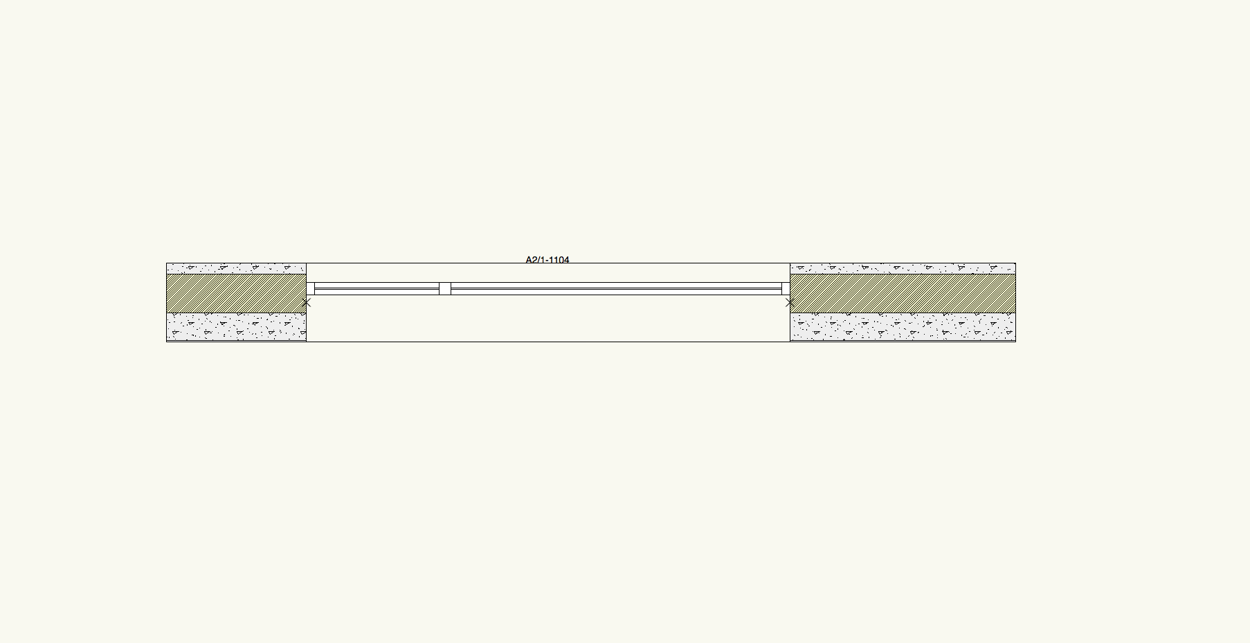
Aren't we talking about different things? I want to make a schedule describing styles (see the image that I attached). Now we are placing a piece of the wall into the model space and making a viewport out of that. That at least saves us the hassle of redrawing all the styles, but we still have to add the text by hand. But since we have about 90 different wall styles in the project, it is a lot of work to update the annotations if we change something.

-
Hi!
Does anyone have recommendation how to make automatically updating wall and slab style schedules? Yes there is a default schedule for wall styles, but that doesn't really do all the things that we need. We are doing it manually at the moment, but I'm wondering if there's any way to automate it.
I need a schedule that includes at least
- an image of the style as it would appear on the drawings (short section of the style in 2d plan view with hatches in the right scale). I can put an image of wall styles in the schedule (but not slab styles), but the hatches are not scaled right and it doesn't look like the walls in the drawings.
- a field describing all the component names and thicknesses in the wall/slab
Has anyone tried making anything like this?
At the moment we are manually placing a section of all styles somewhere in the model and creating viewport of them to annotate and place them on the drawing. I'm wondering if there is a way to automate this or is it better to do it through worksheets. Can more detailed images of the elements be placed in worksheets somehow?
For the components I imagine I have to write a short script to extract all the information?
Thanks,
Taavi
-
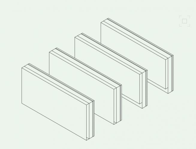
The issue was that in some cases if components are assigned to classes, VW will only export some components of the wall to IFC and others go missing completely. Also when combined with offset wall component heights, the class (IFC layer) of the PIO object is replaced with the class of the first component. I attached the test file that I made, that has 4 walls (with and without component classes, combined with component height offset). I submitted it to Vectorworks through VSS, but as usual I haven't gotten a response about that.
In general exporting walls to IFC worked okay, as long as you don't use component classes or wall caps. Wall features and component offsets mostly worked, but needed jumping through some hoops.

-
Do the wall component classes help with the wall finishes in any way? Or is it just a general tip? We were assigning components to classes earlier, but in some cases it seemed to mess up the IFC export and we had to forgo that. That was on 2017, so it might be fixed now, I have to check.
This is annoying, in Revit-land there are some much more appropriate tools for defining finishes.
-
On 1/5/2018 at 5:01 PM, Gerard Jonker said:
You could leave the finish with a link to the overall class so you'd see a class for each type of finish while still having only one wall style?
Could you explain that a bit more in detail? Do you mean I should assign the wall to a different class based on the finishes?
-
Hi!
I find it difficult to model finishing layers (components) for wall. Sometimes the finishing layers are up to a few cm thick and should be modelled for accuracy. However when the same wall construction can have different finishes, it can get complicated really fast. If I model the finishes as separate walls, I have to duplicate all the openings in the walls as well and keep then in sync when I change the wall itself. If I put the finishing as a component into the wall type, I will end up with many duplicates for the same wall style (wall type without any finishes, with plaster on one side, with plaster on two sides etc.).
Are there any good principles to get around this problem? Is there another way that I'm not seeing?
Regards,
Taavi
-
1 hour ago, zoomer said:
1.
Is it enough if Symbols get an IFC Tag itself or is it also needed that all its components get tagged ?
My impression was that that the symbol definition has to have a tag. Then it will export as one element/component. Otherwise the behaviour was inconsistent.
Also, I could not find any way to export solids and symbols into IFC so that they would have subtags (like the way walls decompose into components or curtain walls into plates and members).
For the other things I don't have much experience with those.
-
17 hours ago, rowbear97 said:
@zoomerWould it be possible to use a worksheet to select objects without IFC tags and then edit from there?
In the Default library at Reports_schedules/Architectural Reports.vwx there is a worksheet Objects without IFC Entity that lists all object without an IFC tag attached. There you can right click on the row header (the gray color thing on the right with the worksheet row number on it) and click Select item.
This is only useful for solids, autohybrids and some PIOs that cannot be styled (railings and stairs). Adding data to windows, doors, symbols, walls and slabs should go through the Resource Browser.
-
It would make a lot of sense that all objects would have some IFC type attached already (like IfcObject). Then they you could see that something some data is missing or erroneous and make the appropriate changes. At the moment these objects just do not appear in IFC and unless you intentionally look into it, no-one will find out that something is missing.
The workaround that I found is to make a worksheet that looks up all symbols without an IFC type attached...
Also, weirdly, if I assign the type IfcObject to an object, it does not show up in the export at all.
-
8 minutes ago, zoomer said:
Even worse, you can't assign a IFC tag when you have selected more than 1 Symbol Instance.
You would need to do that one by one.
You can actually assign the IFC type to the symbol definition in the RB. Or if you change the IFC Data of an instance it asks you if you want to assign the same data to all other instances. However there is still this problem with Project sharing...
-
We have just finished making the first really standard-compliant BIM model with Vectorworks. Vectorworks is indeed capable of producing correct IFC models but there are lots of weird behaviours and bugs that need some kind of a workaround. So, I though I'd share the knowledge I have gathered going through this. Hopefully it will make it easier for those who have to start working with BIM. We worked on VW2017, so some of those might be fixed in 2018 (I have tried some on the new version as well and these have not been fixed).
Following is a list of things that do not work as expected or need some weird workaround to accomplish:
Walls/Slabs
- If the wall profile has been set by dragging the handles for the wall ends, but the profile is still horizontal, the wall exports to IFC with the full height (displayed in the OIP) rather than the where the handles are, even though it shows the correct geometry in VW).
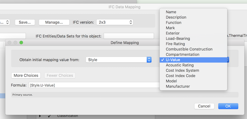
- U-values of wall and slab styles should be written directly into the ThermalTransmittance field in the IFC Data. The style parametric object does have a field for the U-value of the wall (that is also exported to IFC), however this field is not exposed anywhere in the interface to write values into that field.
- When you offset the profiles some of the components of walls or assign some components to different classes, the data about the wall components and thicknesses is not exported to IFC. Also walls are exported by component, data about the materials is missing as well.
- Roof faces are missing most of the IFC data, it has to be entered manually through the style IFC Data option.
- Curtain Walls are exported with the IFC layer field empty (all other objects export the VW class as the IFC layer)
- Wall End Caps export to IFC with the geometry corrupted.
- Wall recesses export to IFC only if they are made with a 2D object, but not with a 3D object (or a 2D symbol). I think it should be possible to accomplish the same thing with symbols with a wall hole component.
Windows/Doors
- The geometry of the window frames is corrupted in IFC— the jambs of windows are not rectangular but in an X shape. Also, both the window and the jamb are transparent.
- Adding U-values to doors and windows through the style IFC Data does not work consistently for me. It is more foolproof to add the value to one of the User Data fields in the style and map this value to export to the ThermalTransmittance field in IFC through the Data Mapping dialog.
- Even though there is a field in window data for frame and glazing materials, this is not exported to IFC. I have not managed to change the data mapping to make those fields export. The best way I found is to write this info to a User Field and change the mappings accordingly.
Symbols
- Symbols are not exported to IFC unless they have an IFC type attached (same is true for solids). They also do not export if the object does not have a fill. This can easily lead to mistakes, because there is not really an easy way to check that all object that should be exported do have a IFC type assigned.
- Symbols export with the IFC layer field set to the VW class that is assigned in the Symbol options dialog (not the class that the symbol instance is actually on like all the other objects)
- If an IFC object is placed inside another symbol, the export behaviour is somewhat unpredictable. If the symbol is a VW parametric object it exports without having a IFC type attached (however it does not create a wall hole, unless the IFC type IS attached). For symbols containing other symbols, it does not export without the IFC type and also makes all the content into one IFC object (that does not decompose into the subobjects).
- Scaled symbols export with the original size not the scaled size.
- This one is actually useful: if you assign an IFC type to a symbol but do not change the name field, it will export with the name of the symbol as the name field by default (even though it does not show this in the IFC Data tab).
Project Sharing
- IFC Export Settings are not saved to the project file on commit. To get them to save you have to turn the project file back into a regular document, make the changes and convert it back to project file.
- Data Mapping settings are stored in the local computer and are not saved in the project file (or a regular file either).
- In a Project Sharing document, the changes made to IFC Data of symbols are not saved to the Project File, changing them needs the same procedure as the export settings.
Miscellaneous
- Adding data to PIOs that cannot be styled is a hassle, because the same data has to be added to all the objects separately. In these cases I have resorted to creating symbols of these objects. I think this gets better with VW2018, even though stairs and railings still cannot be styled.
- Assigning an IFC type to a group does not make it export to IFC.
- Spaces export to IFC only if they have the Show 3D option checked. Also it seems there is no way to make a space object with variable height.
- Parking spaces export as IfcSpace objects. This can lead to confusion, because you cannot differentiate real spaces and the parking spaces. It’s best not to export Parking Spaces at all.
- Solids and Autohybrids are sometimes assigned weird colors in IFC (it seems to depend on the IFC type attached to them).
- Stairs and Curtain Walls decompose to subobjects in IFC that do not have any data attached (the object that contains them does have all the data though).
- Some BIM standards expect object in IFC to have two levels of names, a generic name (Type Name in Solibri) and a specific name (Name). It seems that Revit and Archicad make use of these two levels to organize the objects and styles, while Vectorworks resource structure does not (this might be changing with the new window and door catalogs in VW 2018). The content of the Type Name field can be controlled for most objects in some way or another, but it seems easier to just declare that the content of this field does not matter.
-
3
-
We are have to do a formalized BIM process now, where every engineer is producing IFC models.
Importing the IFC model into a separate VW document and referencing it to the model seems like the best way, I've found it easiest to create a separate layer for the DLVP and switch the layers in it on and off as needed. Since the engineers are constantly producing new models, it's easier to update one reference rather than one for each story.
If you need to produce valid IFC models, then architects and engineers should make their own objects and just keep them in sync. Every object in the ifc model has to have it's own unique GUID, hence copying objects from one file to another does not work well with this. We are using Solibri Model Checker to run a conflict check and see where the object are not aligning and should be corrected.
Of course if you don't have to produce a IFC model yourself, you don't have to worry about the GUIDs and could theoretically import the engineers model into yours.
It's also worth noting, in our case engineers only model the load-bearing structures while architects model everything.
-
Hi!
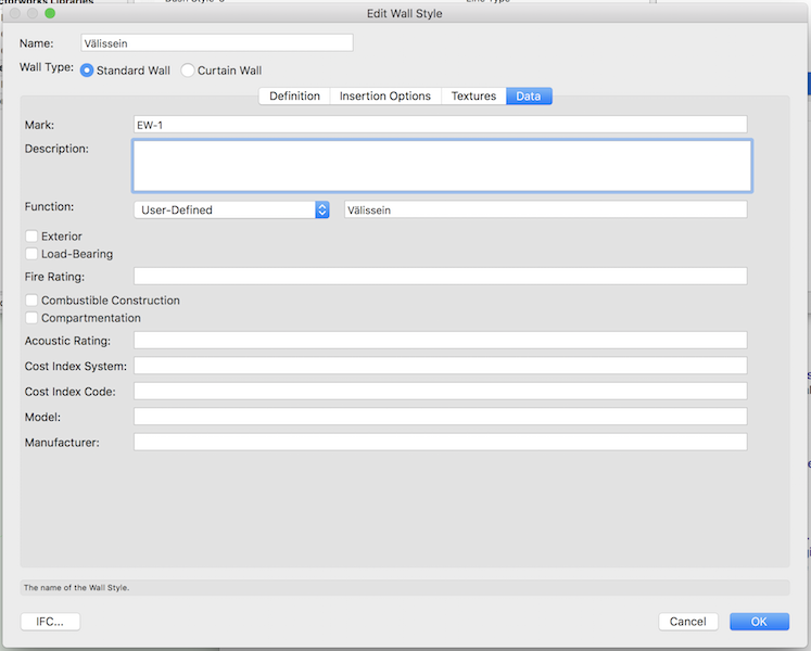
I'm trying to attach the U-value to wall styles for exporting it to a IFC, but there's a weird inconsistency in the settings. In the IFC Data Mappings tool there is a list of properties which can be exported to IFC. Most of these are visible in the wall/slab style data tab, with the exception of U-value. I can query the value in a worksheet ('Wall'.'U-value'), however this just shows 0.
Does anyone have experience with that? Where can I set this variable for the wall/slab styles? Is it dependent on some setting or a preference that the U-value is not shown in the data tab?
Thanks,
Taavi


Wall With Interchangable Assemblies
in Wishlist - Feature and Content Requests
Posted
@AJIsaaks To put it in perspective, we had a recent project (a new building), where there were over 300 wall styles and over 150 slab styles. The problem was the same, that there were a number of wall cores and then a number of finishes that could be applied to any of the cores, the combinations get out of hand quite fast.