TheatreG
-
Posts
9 -
Joined
-
Last visited
Content Type
Profiles
Forums
Events
Articles
Marionette
Store
Everything posted by TheatreG
-
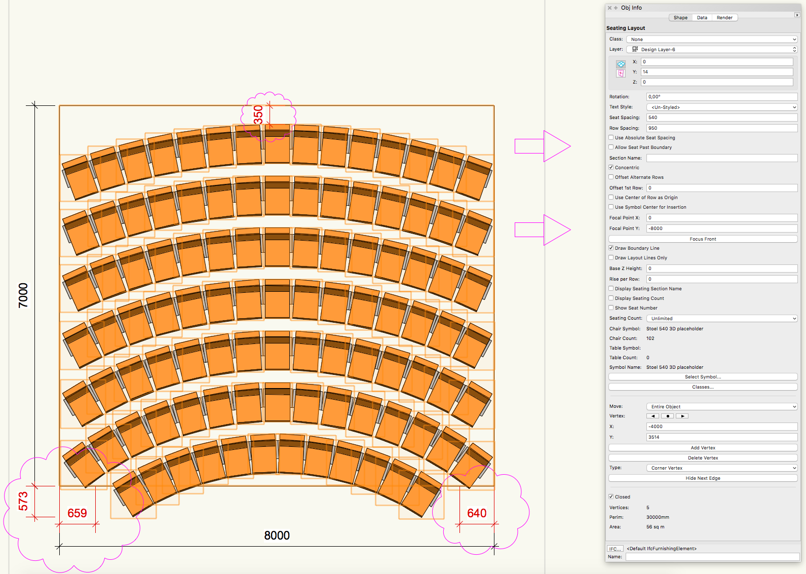
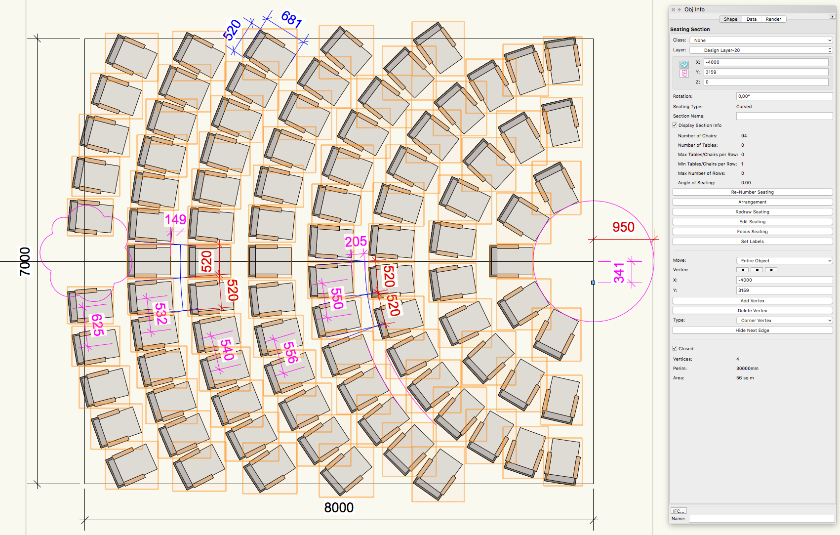
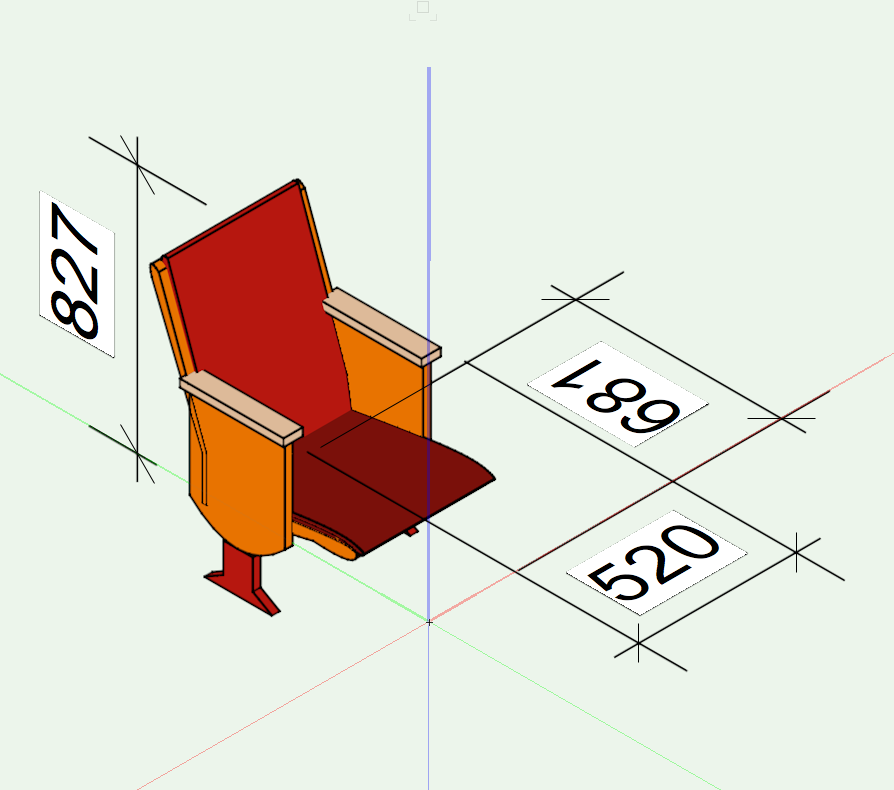
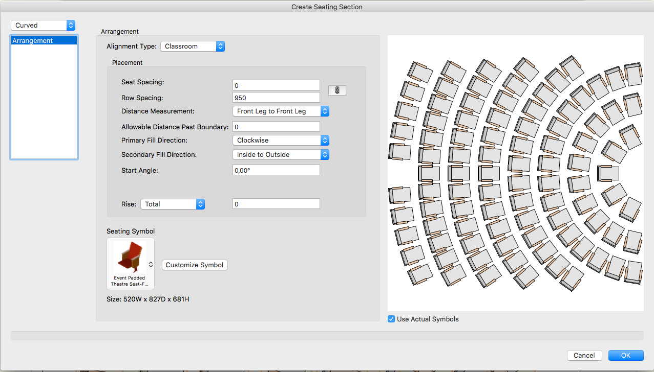
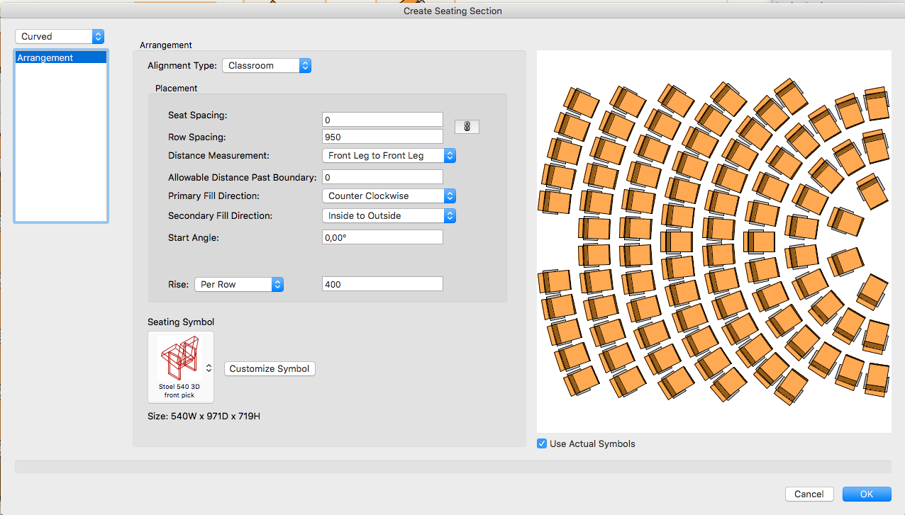
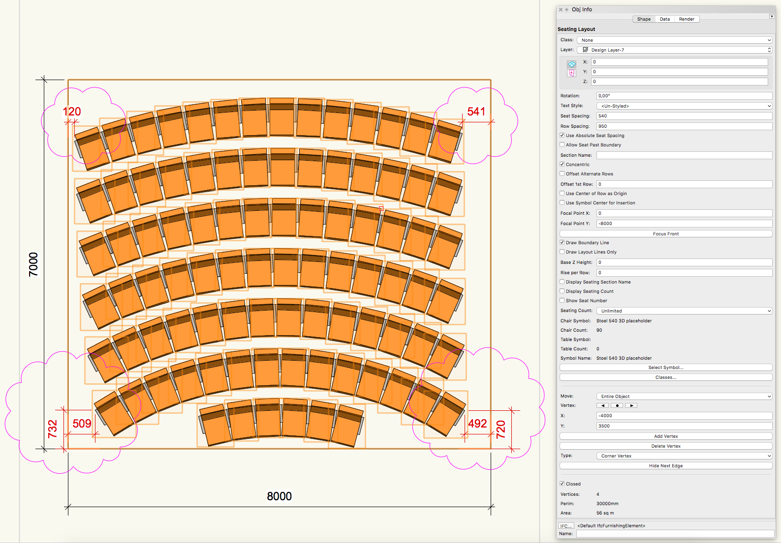
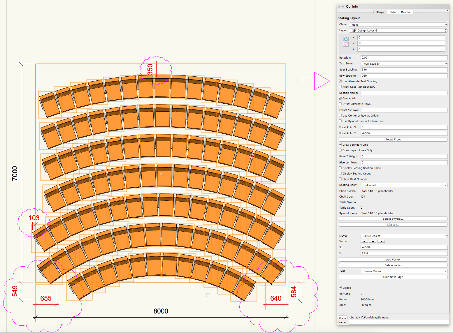
Hi Kevin, You are absolutely right with the flipping debth and hight of the seating symbol in the Arrangement box. Good find! Besides that the seating symbols themselves which came with the library seem to be a source of faults. The dimensions of the 3D component don't match with the dimensions of the 2D component, and the drawn parts of both components seem to be not 100% centered. I discovered this issues using the "Event Padded Theatre Seat" and also using the "Event Bleacher Seat". After editing the "Event Padded Theatre Seat" and setting the insertion point to the front center of the seat I made another "Seating Section" layout to see if I can reproduce a symmetrical seating layout using this symbol. And yes, once again I got a symmetrical seating layout, but still with the same restrictions and "buggy" issues as mentioned before. As I am not sure what kind of variable you could miss when trying to reproduce my simple design, so I will try to explain what I am doing step-by-step: First I draw a rectangle with the dimension 7 by 8m with the centre of the rectangle exactly on the zero point of the X and Y axis. To be able to control the position of the boundary I copy-paste this rectangle to its original position. With this rectangle selected I use the "Event Design" > "Create Seating Section" tool and pick the centre of the right-hand side of the rectangle as the Focus Point. When the "Arrangment box" pops up I choose "curved" instead of "standard" on the upper left button, fill in the row spacing of 950mm, and set the "Distance measurement" to "Front Leg to Front Leg". The resulting seating layout is centered, but again with an offset along the Y-axis. In this case the offset is 341mm instead of 360mm as before (maybe due to the use of a different symbol with different dimensions ?). The last step is to move the whole seating layout down along the Y-axis (in this case by 341 mm) to compensate the offset. I have NOT edited the boundary at all. Here are some screenshots of this layout and my settings: I am happy with getting a centered layout, but I am still unhappy with some issues of the "Seating Section" tool: 1. The curved seating layout does NOT respect the boundary 2. The "Seat Spacing" settings seem to have have no effect on the seating layout. I would expect that "Seat Spacing" settings would do the same as "Absolute Seat Spacing" does in "Seating Layout". Besides the option to choose extra space between the seats IMHO also an option to choose LESS space would be useful to finetune a seating layout. 3. For unknown reasons the last row shows a gap in the middle 4. IMHO the "Focus Point" definetly should not create any offset at all and should always be on the centre line, especially in case of a curved seating layout. Regards, George
-
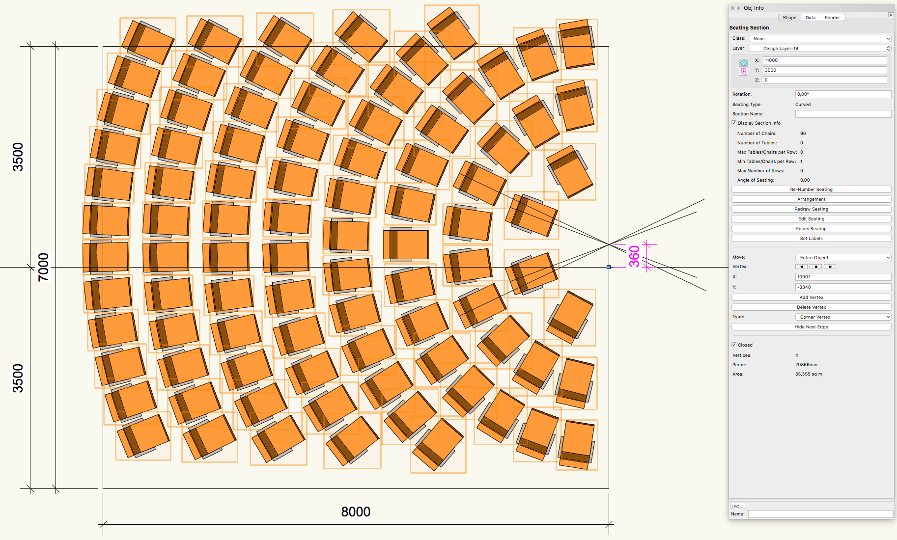
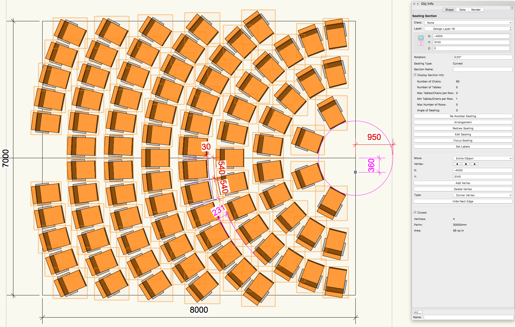
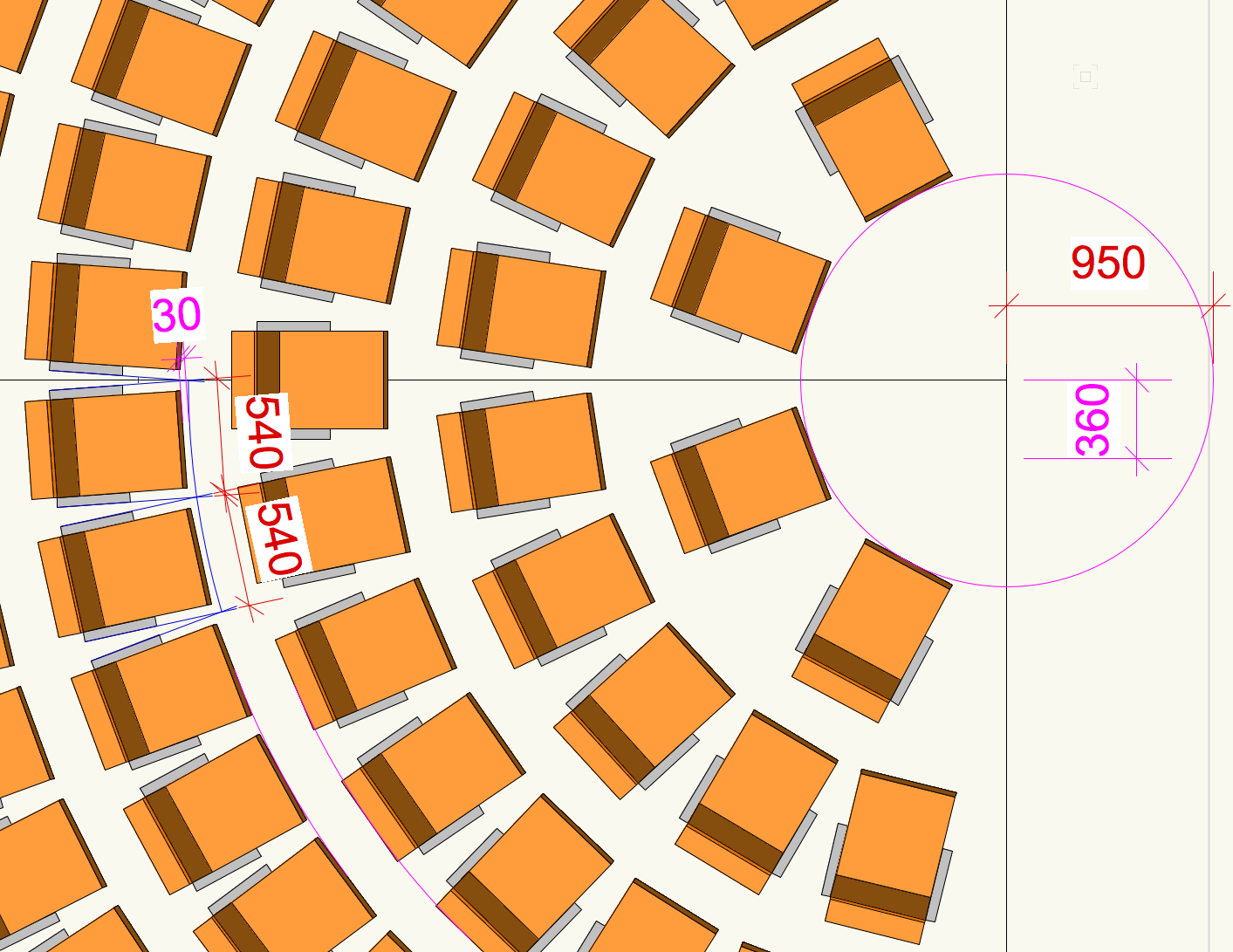
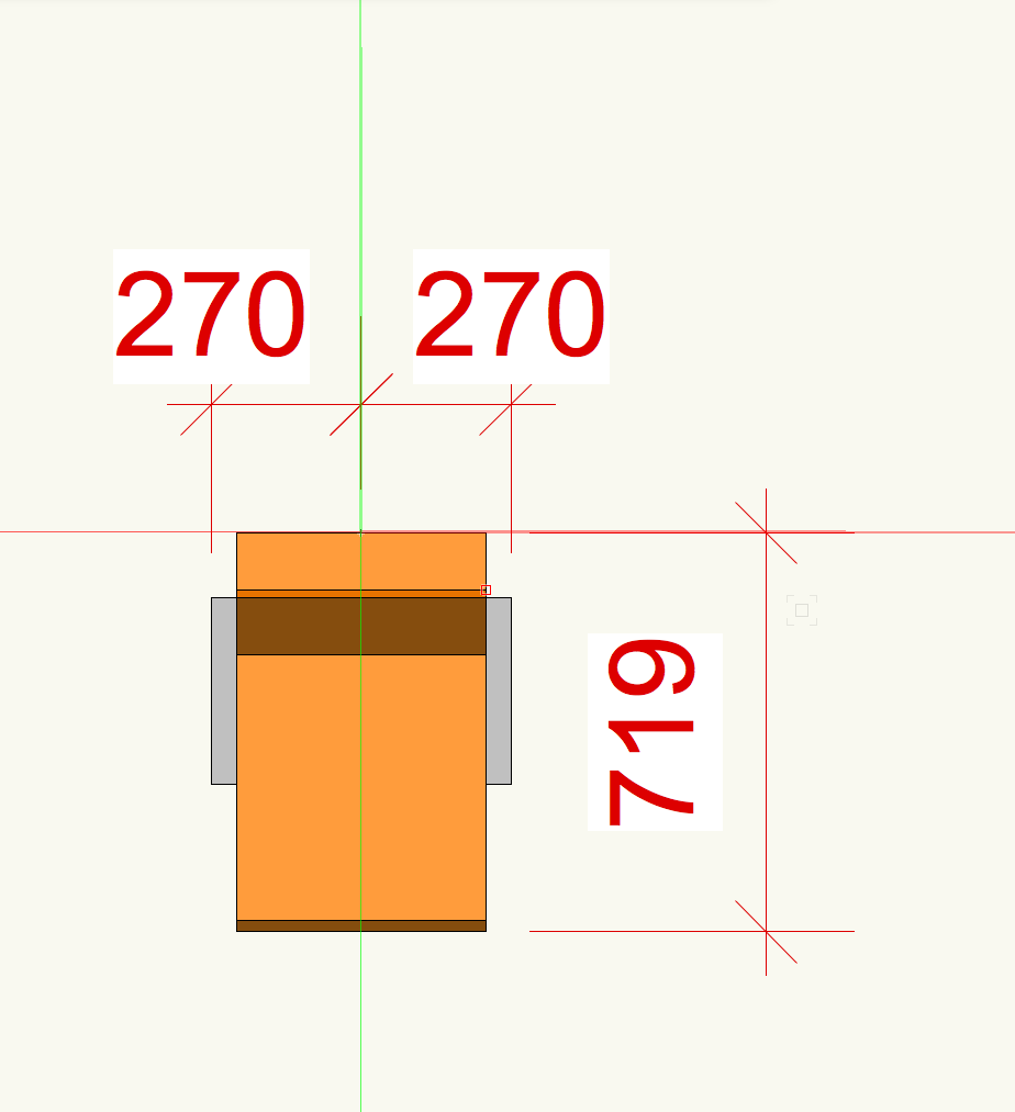
Dear all, Playing with the "Seating Section" tool (VW2017/Event Design) I finally succeeded in creating a curved seating layout that is mirror-symmetric to a centerline, but I still have to deal with some strange and/or surprising decisions Vectorworks makes: When creating a curved "Seating Section" based on a rectangle the whole resulting seating layout seems to be offset by 360mm up along the Y-axis. The blue snapping box that should symbolize the focus point is placed on the original center line of the rectangle, but that position is off-center to the seating and therefore is NOT representing its focus point. Moving that blue snapping box along the X-axis DOES move the focus point, so there seems to be some kind of link between the blue snapping box and the focus point anyway. Besides the fact that "Seating Section" is not respecting the boundary, the arrangement of the seat symbols still seems inexplicable to me. With the origin resp. the insertion point of the chosen seat symbol exactly mid-front of the seat and a seat-width of 540mm I would NOT expect Vectorworks to arrange the seats along an imaginary curve some 30mm in front of the seats. My settings in the "Arrangement" box: A detail of the two offsets (360mm resp. 30mm): Any help would be appreciated a lot ! Regards, George
-
Hi Kevin, You are right...so far I have only used the "Seating Layout" tool. Sorry for the confusion ! Regards, George
-
Hi Kevin, Thanks ! When I right click on the seating layout I can only choose "Edit path", but that works the way you described ! Concerning the problem you have with the number of seats: Do you have "Use Center Of Row As Origin" activated ? Try to dectivate it, maybe this helps. Regards, George
-
Hi again, Thanks Kevin and Brandon for all the additional information and comments ! Another one on my wishlist would be the possibility to replace the original "boundary" easily by a different one. It would be great if this would work the same way as for extrudes (i.e. simply replacing a square footprint by a triangular one)! Regards, George
-
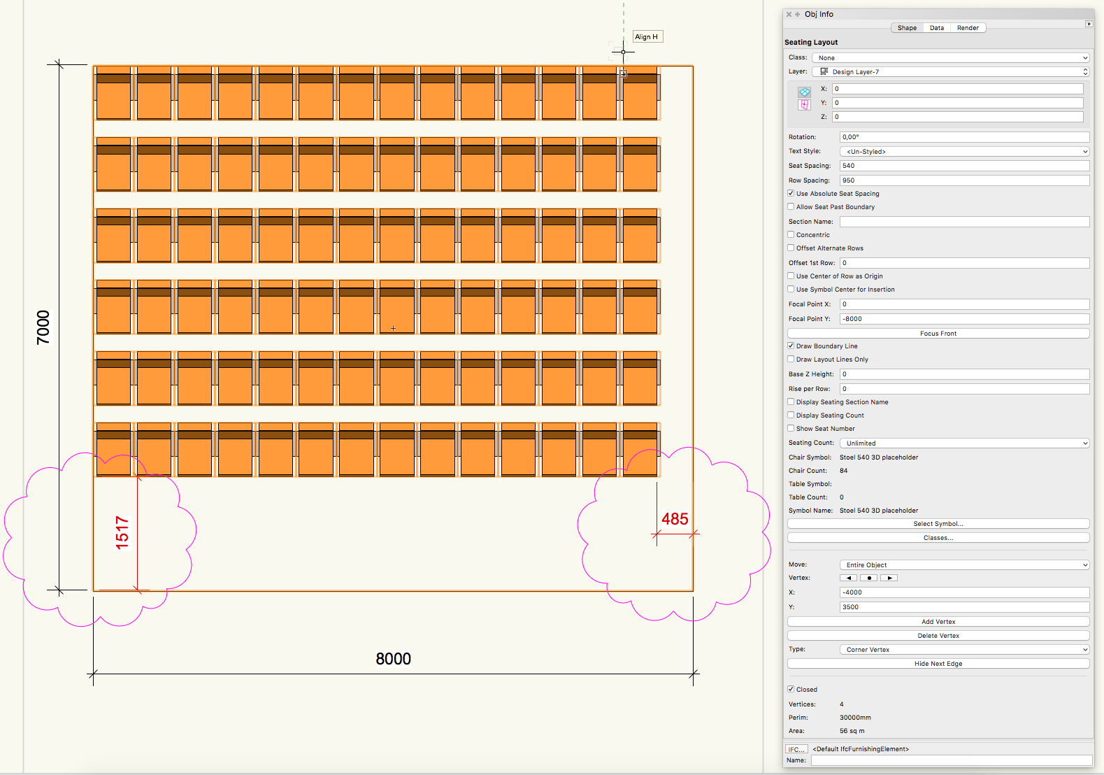
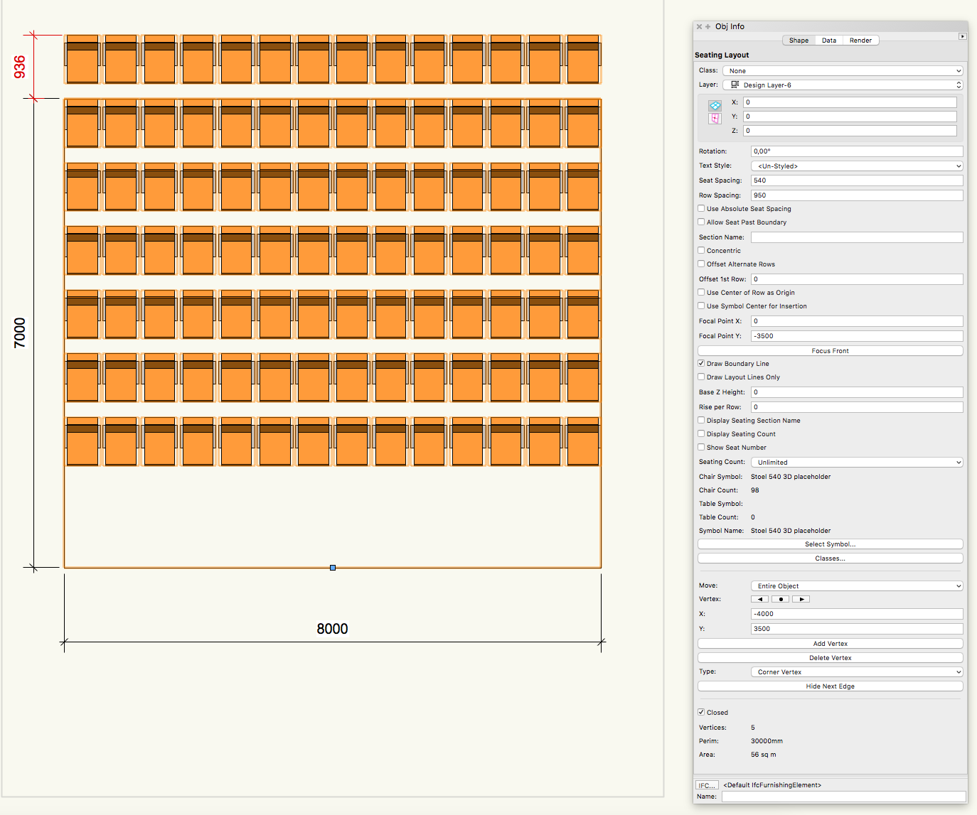
Hi Brandon, Thank you for the suggestion! I just tried the "Create Seating Layout" command in VW2017 (Spotlight > Architectural > Create Seating Layout). Besides the fact that it is quite irritating that there are different commands to create seating layouts, it is even more irritating that the results are not the same. Starting again with the most simple seating layouts the only difference I can see is that now the seats do stay inside the boundary when "Allow Seat Past Boundary" is disabled. Horizontal and vertical alignment still seem random to me: Straight rows using the "Create Seating Layout" command: Concentric rows using the "Create Seating Layout" command: I know that there often are several workarounds and options to get a better result, but I would love Vectorworks to create a seating layout centered to the middle axis AND beeing based on comprehensible parameters as a starting point for further customization. To me it seems the most logical to use the middle axis as the starting reference and to make the seating layout mirror-symmetric to that axis. With a focus point exactly in the centerline of the rectangle created in the beginning I really would expect the seating layout to be mirror-symmetric, but that is not what I get. Besides this I would expect that the depth of the first row is exactly what is filled in at "Row Spacing" (plus the chosen "Offset 1st Row") for a straight row layout. In case of a concentric seating layout I would expect the minimum depth of the first row to be exactly what is filled in at "Row Spacing" (plus the chosen "Offset 1st Row"). But again this is not what I get. As mentioned before the "Seating Layout" could be a very useful tool when it comes to entertainment design, but therefore it should be more logical in my opinion. Maybe a big wish, but hey: Christmas is not far off ;-) Regards, George
-
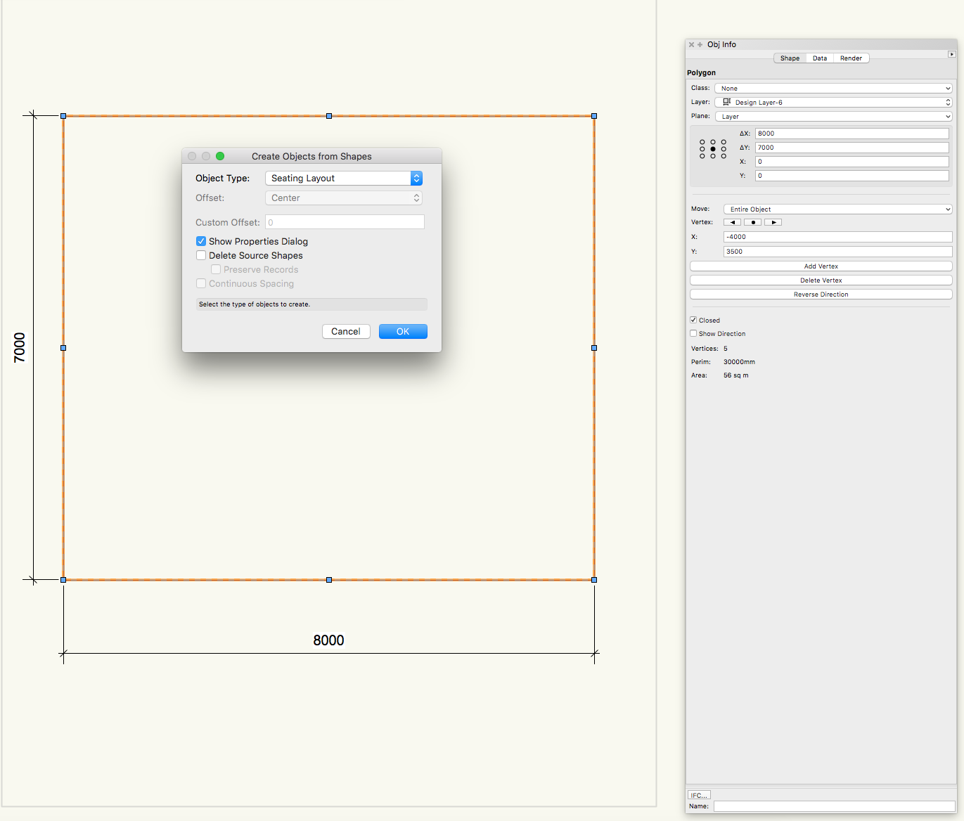
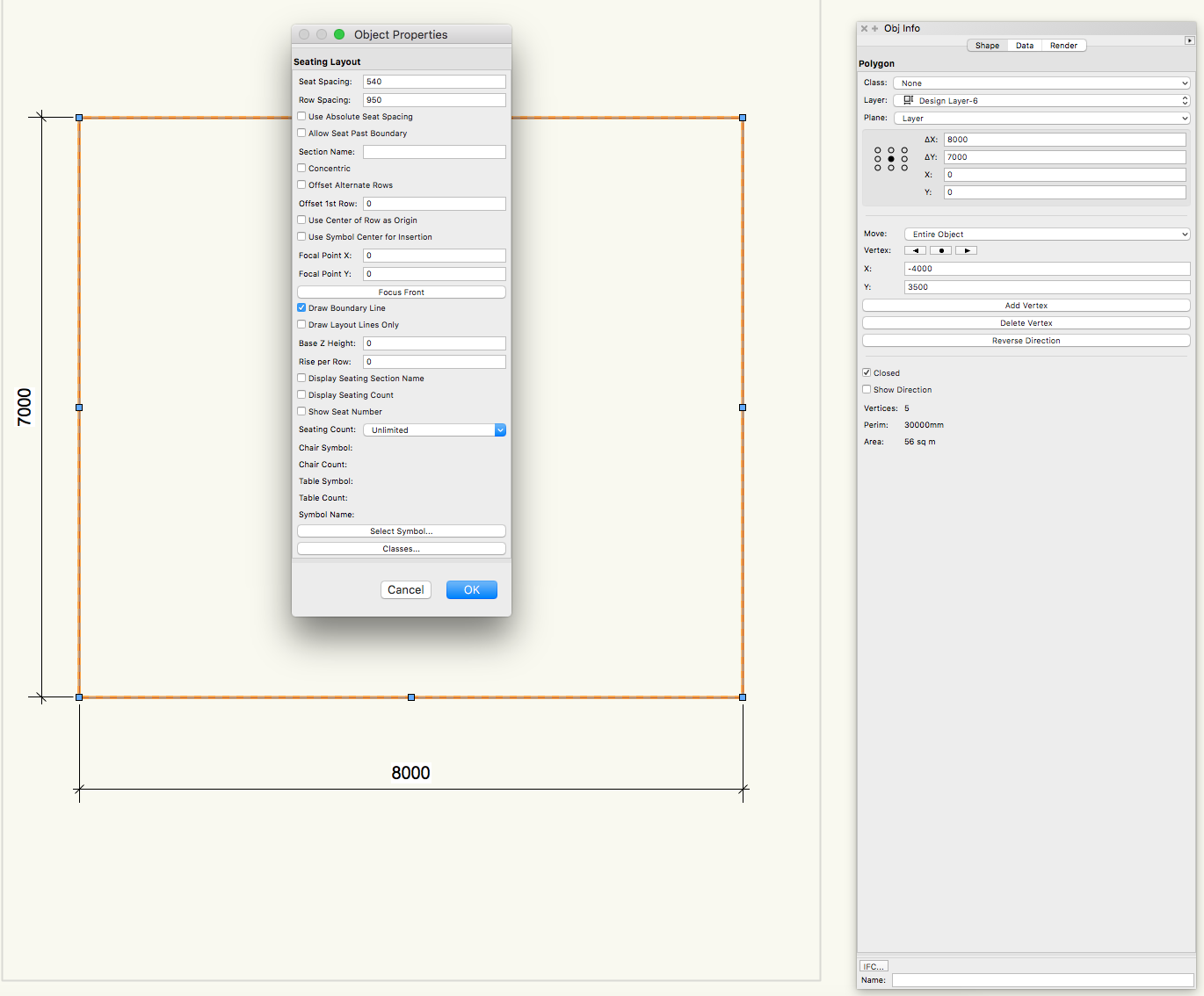
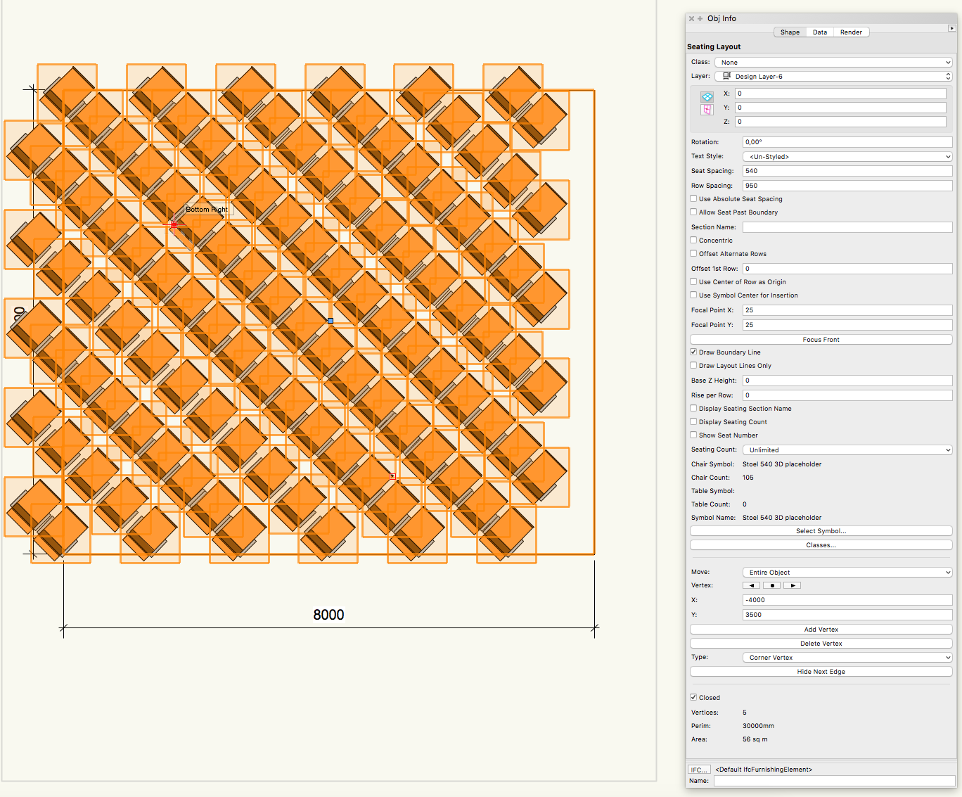
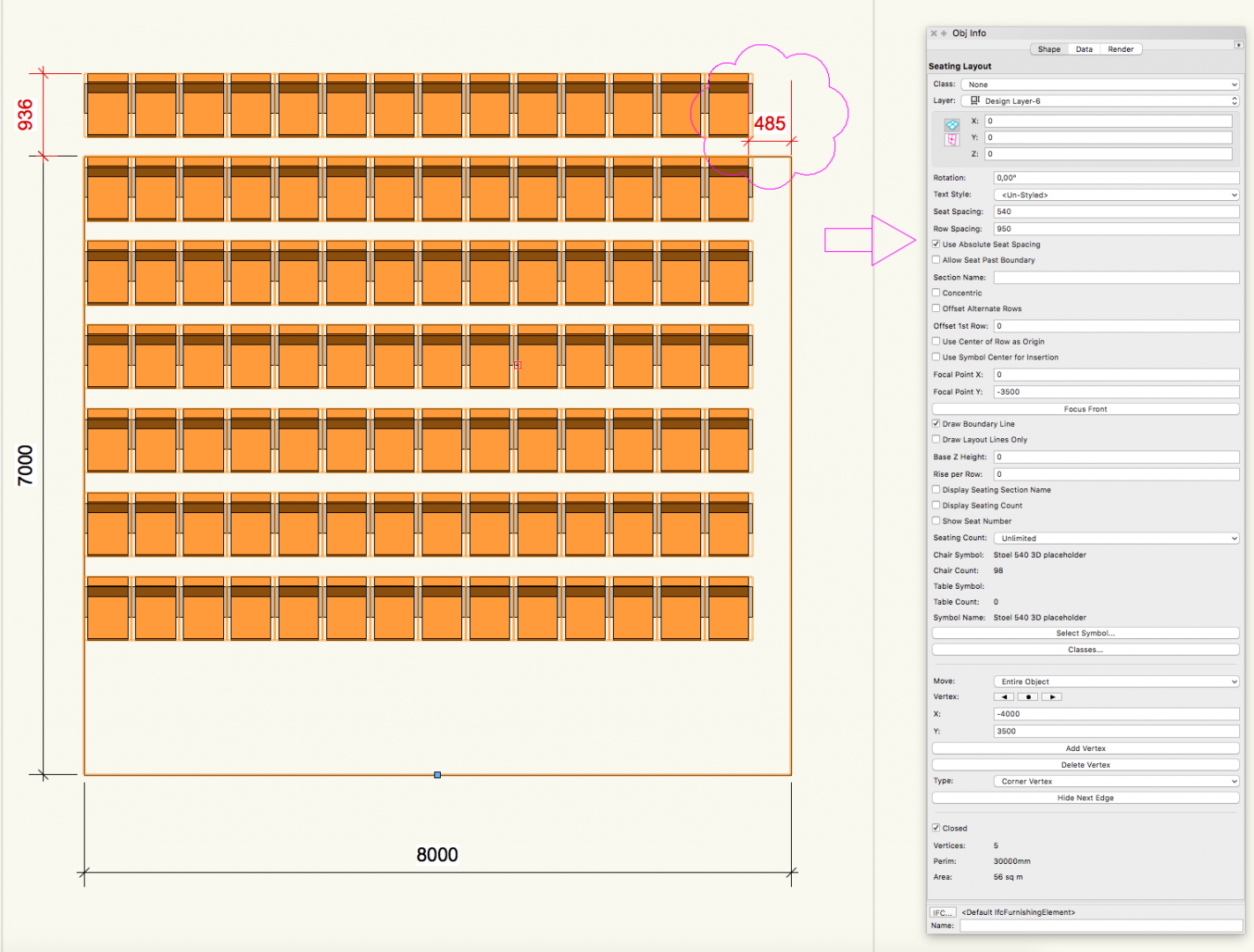
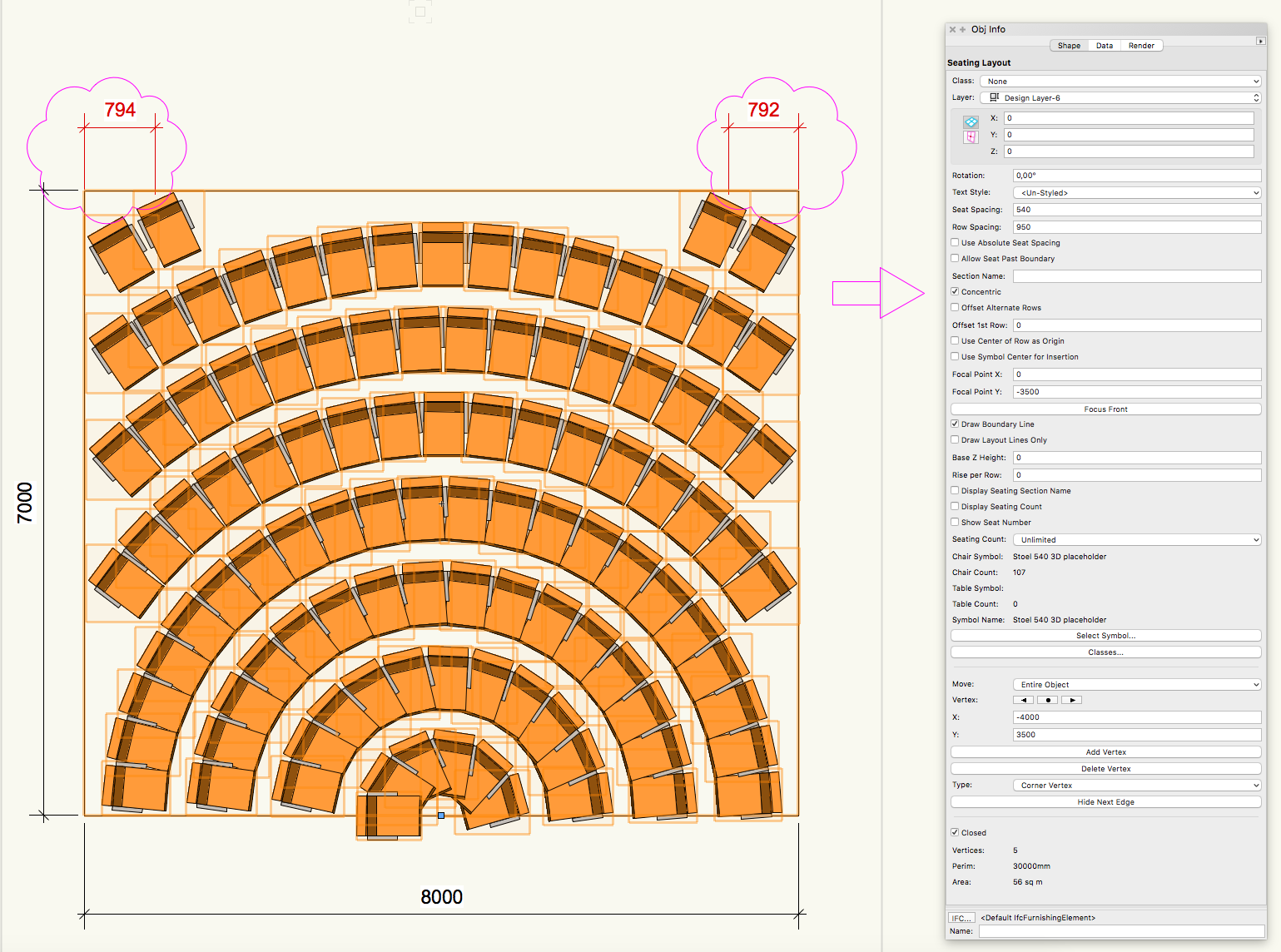
Hi, We are 8 months further since the last post, and I was wondering if the seating layout issues were solved by now. So I started to play a little with the seating layout tool in Vectorworks 2017, but IMHO this tool unfortunately still does not work as it should. My expection for ANY tool (in any CAD program) would be that it does work with 100% precision, and that it does what you expect it do do. To be sure that it is not me causing the bad results I would like to share how I have used this tool in another step-by-step overview: 1. Creating a seating layout based on a polygon 2. Setting the seating layout properties 3. First seating layout I got 4. Seating layout after using "Focus Front" 5. Seating layout after using "Use Absolute Seat Spacing" For a simple seating layout like this with straight rows I would expect the seats to stay centered when using the command "Use Absolute Seat Spacing". Furthermore I would not expect any seats outside the original polygon when not using the command "Allow Seat Past Boundary" Going further with concentric rows (starting with "Use Absolute Seat Spacing" deactivated) the whole thing became even more mysterious: 1. Using "Concentric" 2. Setting the "Focal Point" 3. Activating "Use Absolute Seat Spacing" while "Allow Seat Past Boundary" still is deactivated So also the concentric seating seems not to be centered and also seats have been drawn outside the boundary although not permitted. Horizontal and vertical alignment of the seating seem to be random to me. Last but not least the seating symbol I used: In case I made some crucial mistakes It would be nice to hear how to get a good workflow out of the seating layout tool. If the described issues seem to be bugs it would be highly appreciated if the seating tool could be updated to a functioning tool. In architectural entertainment design the seating tool would be very helpful, but only when it works as expected. Thanks a lot! George


-
Dear all, recently we started a BIM project in VW 2016 SP2 that we need to share as IFC with other parties. As a standard we use the VW classes to give local building classifications to the different building elements. While in VW 2015 those classes were automatically included in the export to IFC (shown as "layer" in the Solibri model viewer) this information seems to be lost when exporting from VW 2016. Also we could not find back other information we gave to symbols like VW IFC ObjectType, VW Classification_Classification Source, VW Classification_Classification Edition, VW Classification_Classification Edition Date, VW Classification_Location, and several other data we added to the "Export IFC Project" sheet. Furthermore a re-imported IFC (that we exported ourselves before) seems to loose some information compared to the original VW file (and compared to the Solibri viewer as well). Could we solve this by changing some settings in VW 2016 SP2, or is this about bugs to be solved in the next service pack ? Any suggestions are welcome ! Best regards, Georg