halfcoupler
-
Posts
460 -
Joined
-
Last visited
Content Type
Profiles
Forums
Events
Articles
Marionette
Store
Everything posted by halfcoupler
-
 ok, the rule seems to be that there are 2 differend types of extrudes, (please correct me if I'm wrong): - 1) Extrudes based on non closed 2D-polylines, which apper as "shell-extrusion" - 2) Extrudes with other (vector-) mathematical definition like circle, oval, rectangle, closed polygons and arc, which appear as "solid-extrusion" The only way to get the "shell-extrusion" from the second type is to convert it to non closed 2D-polygons before extruding Extract tool is no option for getting extrudes, since it results in a nurbs surface, not in an extrude.
 -
Select Similar tool inside Clip Cube
halfcoupler replied to halfcoupler's question in Wishlist - Feature and Content Requests
Just stumbled over this, maybe someone here finds it helpful: The Select Similar tool has two modes: The second mode is to search only within selected objects, so when selecting all objects within a clip cube the Select Similar tool can affect only these objects. So no need to have a special tool for this.- 1 reply
-
- 1
-

-
I think in the end it's a mathematical problem, if you want to keep the measurements and the locations precise, the vectors of the boraders will always point to the same line. The only way to differentiate the lines is to send them either to front or to back. No chance to show them simultaneously. Something else you could try is to experiment with the double line tool. This tool allows you to draw a second line beside the original line, which could be something like the "inner boarder" that shows up in the viewport but is not in the calculations.
-
anyone knows why this is so ?

-
Have you tried to create several viewports, one for each property , crop them and place them adjacent or with some gap beneath each other on the sheet layer ?
-
Ooooooh, seems to be that simple: Symbol and nodes within the wrapper, wrapper converted to object node .... that's it ! Something has blocked my brains ! Thanks much !
-
I want to create a marionette object out of an existing symbol. For example the symbol should get an x-parameter that moves the symbol in x-axis by this value or is mirrored along two parameter points. How do I tell the network which symbol should be handled ? Do I have to put the symbol into the wrapper or do I have to put the wrapper into the symbol definition? Or do I have to convert the symbol to a group and handle this group with a special node ? How do I create such a plug in object ? All example networks I found do the drawing from scratch, which is "draw a line or rectangle and do with it whatever the nodes say". But what I want is: "Take this symbol or group and do what the nodes say". I was successful with creating marinoette menu commands which use the [Objs by Crit] - node and does what I want with the object that matches the criteria. But I want to have Objects with marionette parameters in a library that can inserted to my file. ( = Object nodes with "pre-defined drawing" ? ) I fear I'm completely tapping in the dark, and maybe completely misundestand the use of Marionette.... Maybe someone can show me a simple example file with a symbol or group that is somehow controlled by marionette ?
-
ok, should have done this earlier, I asked google and all is answered in this great video 😀
-
Just playing around with some wiring diagrams, checking things out... - Is it right that the multicable tool does not work in 3D with 3D polygons ? (except having the 2D polygons as layer plane objects),- It would be great to draw 3D polygons all across the venue and have this as cable tray. - does anyone know wether it is possible to offset the Break Out labels and the cable length labels like it works in the dimensionig tool ?
-
Not tested yet: I guess the tools work only with the "User Data and Preferances" folder, wheras the data in the "Workgroup and Project Folders" only give general (shared) access to the file recources, like symbols etc. ? Maybe its even a question of having "Design Series" installed ? Is there somewhere an example (screenshot) of how a typical workspace folder looks like ?
-
Hi Pat, so this is the reason why the "Replace..." button in the OIP works only with the favorites folder on the local harddrive ?
-
Hm, one of these VW miracles,- I'm using the replace button a lot, ( in fact not only a lot, I use it permanently...) and it's definitely uncomprehnesible why this does not work on network files... Bug or feature ???
-
I have tried to use workgroup files instead of favorite files. It speeds up the process of selecting and importing symbols via drag and drop tremedously. But when it comes to replacing symbols I find that symbols can NOT be replaced by symbols from workgroup files. Is it correct that the Replace... button of the OIP does only select objects from open files, vectorworks libraries or favorite files ?
-
Just stumbled on the following issue: Some of my favorite library files have more than 450 mb now. I have tried to make these a link from a server directory for having it in the automatic server backup. This slows down the importing and replacing of symbols to an inacceptable speed. I ended up in having all favorites as local files on the local harddisk, doing a manual backup from time to time. So the size is really a big problem when working on network.
-
Exporting to pdf - vs. image file - file size
halfcoupler replied to halfcoupler's topic in General Discussion
Yes, you are right, converting only the viewport to jpg seems to have the same size-reducing effect as exporting the whole sheet to jpg, and you can keep the pdf-format. But a problem is that you always have to keep two two copies (one with viewport and one as jpg) of the sheets and manage all this, which is quite time consuming when having 20 or more sheet layers. Yes, this should really be a publishing option! I thought "rasterize pdf" would do this, but this seems to do something else and it increases the file size instead. I just wonder if anyone ever uses this option ? Seems to be an ancient leftover from previous versions. -
Exporting to pdf - vs. image file - file size
halfcoupler replied to halfcoupler's topic in General Discussion
Just tested it out: Converting the viewport to bitmap and publishing the sheet does not reduce the file size as long as the bitmap itself isn not reduced in its resolution. But this method is a good way to control file size vs. quality and keeping the pdf-format. A big advantage of exporting directly to image file is that very big plans which won't fit on standard paper sizes can be exported in good resolution and accectable filesize just as a "zoomable on screen overview" especially for smartphones and tablets. In the end it's a question of the purpose the sheet is made for. I'm using the following methods: - hidden line viewports for anything that is flat and / or 2D and has to look like a technical drawing, exported as pdf or dwg - medium Open GL viewports for concept drawings or schematical overviews, or 3D section viewports with clip cube, either as pdf or jpg - final renderworks or "very high open GL" for anything that is for presentation usually for direct print to printer. -
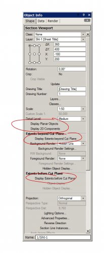
solved... it seems that VW 2019 can't handle the ancient Windows-Classic Desktop design. Switching to some more modern design letss all checkboxes appear again.
-
Don't know whether this a Windows 7 Problem, a Vectorwoks bug, or just my desktop settings: Since VW 19 I can't see a difference whether butons like "Display Planar Objects" or "Display Extents before Cut Plane" are selected or not. They do what they should do, but I can't see what I have told them to do... Maybe on Mac or Win 10 this screenshot looks completely different ?
-
Class Visibility in Thumbnail Renders
halfcoupler replied to Haydenovative's topic in General Discussion
I'm not shure, but I guess you did not see that after importing you will have two instances of the symbol shown in the resource browser as thumbnails: One ist the (imported-) symbol from your current file whose thumbnail will be shown with the settings of this file, and the other one is the symbol from the library source file which is shown with the setting of the library file. If you want to change the thumbnail view of the library file you have to open this library file, locate the symbol there, edit it and save the file. If you want to change the thumbnail of the file you are just working in you can just edit it there. Depending on which file you edited the resource browser may need a refresh after editing to see the changes. -
Maybe this helps: For viewport renderings there is a setting in the preferances: Document settings / Document Preferences / Display / Save viewport cache
-
Class Visibility in Thumbnail Renders
halfcoupler replied to Haydenovative's topic in General Discussion
ah, is it the thumbnail views in the resource browser you mean ? I think they simply show up with the classes that were used last time the symbol was edited. To change the class in which they appear, double cllick on the symbol, choose classes as needed in the navigation palette, exit symbol and save file. If the symbols are in a favorite file, open this file, open the symbol, do as above, save file. -
hey twk, you are my hero !!!!!!!!!! These inteactive settings were totally mixed up. Pressing the reset button worked ! many thanks !
-
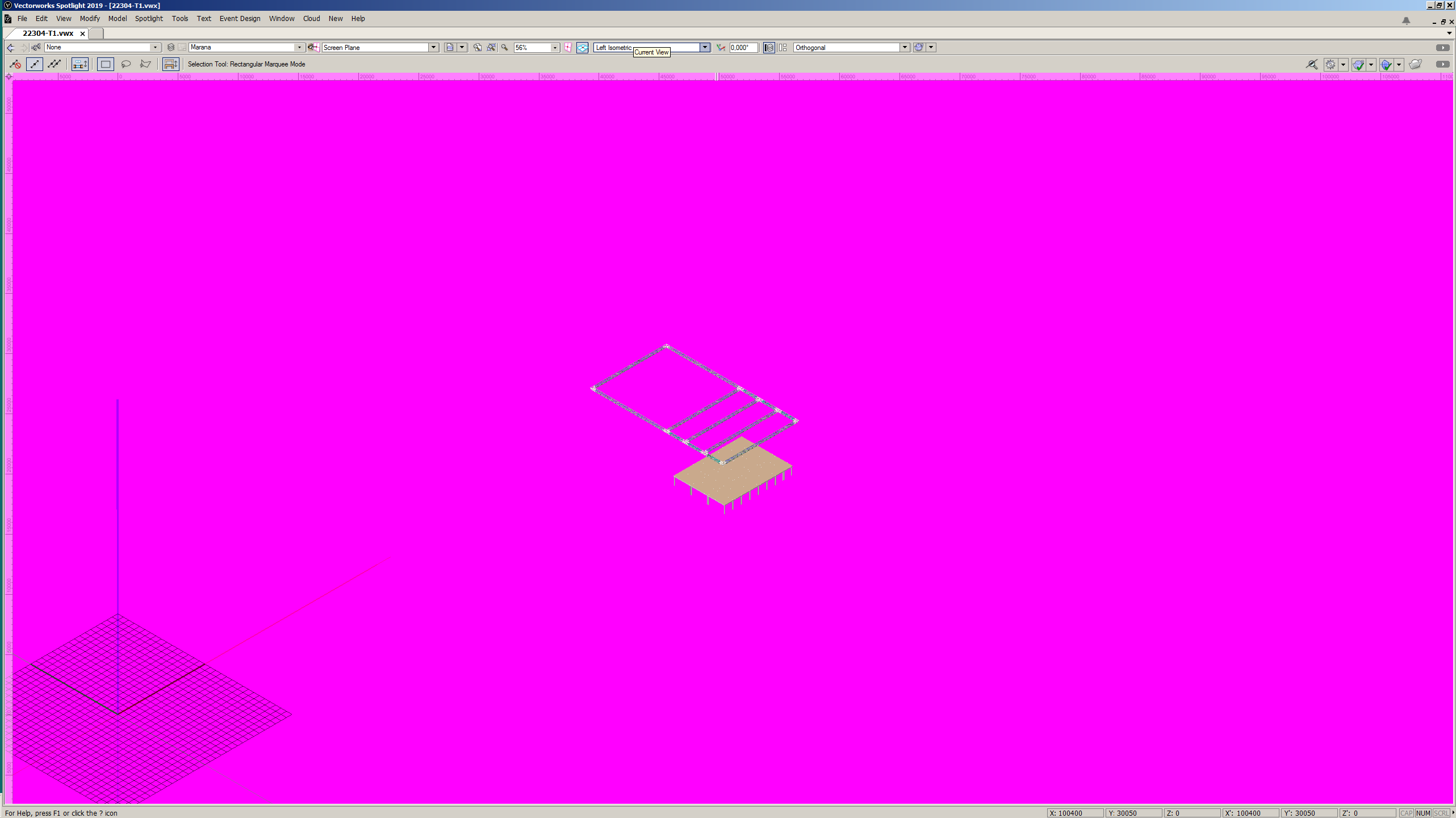
Help ! I swear: no alcohol, no drugs and newest grafik driver ! Suddenly my VW- background got purple and stayed that way: At first I thought my grafic card is broken but I checked the system with VW 2018 and everything works fine. I must have accidently changed some hidden settings, but can't find which ones. - Preferances/Black background is turned off in my preferances, turning it on leads to a white background but selected items that should be red are white. Anyone knows a way to correct this, or, in worst case, a way to backup and reset all personal settings ?

-
Class Visibility in Thumbnail Renders
halfcoupler replied to Haydenovative's topic in General Discussion
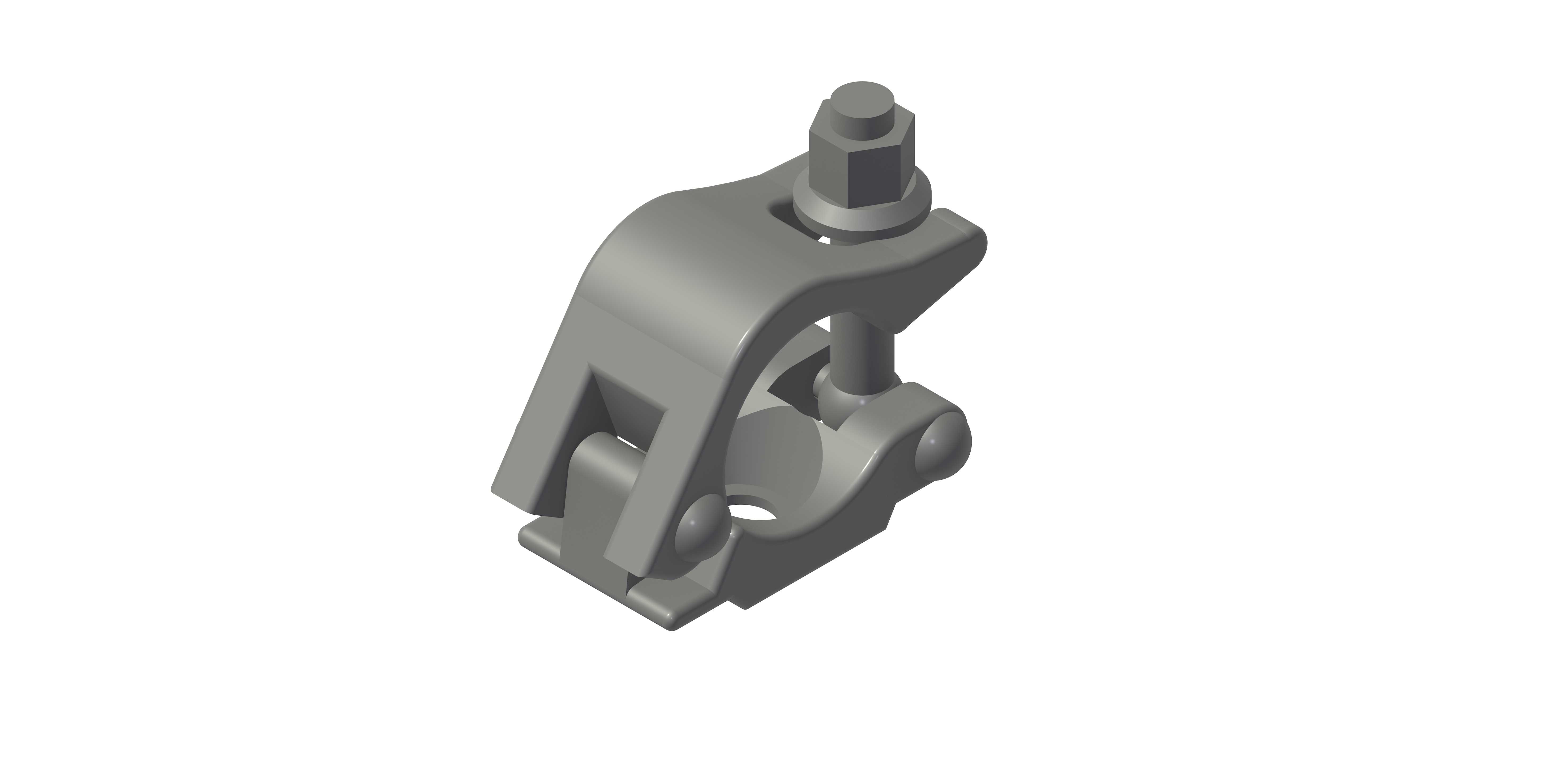
Don't know if thats what you mean: I have made my own truss symbols with two classes inside the symbol, one showing the whole body, and one showing only the achsis of beam and brace. When you set up views only with the according class visibility you can toggle between these views. This is very useful when you have big scales like 1:200 where details like fork ends have no importance and slow down the drawing.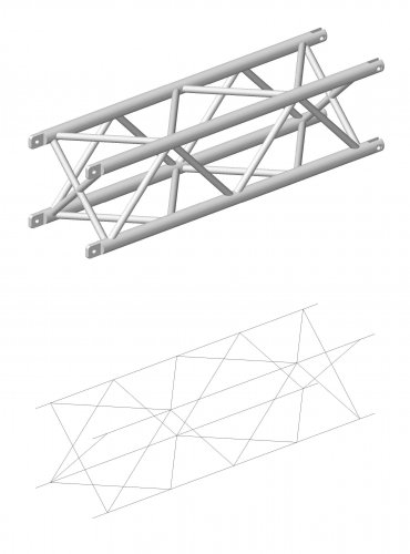
-
3d Locus not visible in wireframe Orthogonal view
halfcoupler replied to Dubman's question in Known Issues
Yes, seems to be fixed with 2019