

halfcoupler
-
Posts
461 -
Joined
-
Last visited
Content Type
Profiles
Forums
Events
Articles
Marionette
Store
Everything posted by halfcoupler
-
 There is one workaround that does the trick: - select all instances of the symbol you want to change. - use the replace button of the OIP to replace these instances,- but NOT with the same symbol, choose any other arbitrary symbol you want. - leave everything selected, and repeat the replacement with the right symbol you need which has the correct values attached. VW always overwrites the record format when it is not identical to the format that you are importing. I think somewhere in the preferances this behavior can be adjusted to "overwrite" or "merge".
 -
Indeed the problem is that virtual parts can not be treated like other objects in a worksheet. A trusspin is a good example: It may exist as Symbol, but no one wants to add 450 trusspins to a drawing. My workaround for this: - a simple record format with a Count (integer) field and a Name (text) field - a separate Layer for additional parts or spare parts. => Draw any object or symbol, add the record format to this object, fill the Name-field with "trusspin" or whatever and add the amount to the count field. As drawing object you can even use a textfield "450 trusspins" for this. These objects can be treated in any Database Worksheet like any other object and so it is possible to design any custom equipment list you want. The design layer then gives a great overview of anything additional to be packed in the warhouse. So, as a job handler, you can see what item you have already taken care of and what is still missing. Maybe future versions of virtual parts could integrate this workflow ?
-
This does not return to the active Layer Plane, it only hides the pink square,- which may cause some strange things happen when working with 2D tools in a 3D environment, since you don't see that a working plane is active. You can toggle Working Plane / Active layer plane in this way: If not already active, You need to activate the working plane palette first,- Go to Menue: Window/Palettes/Working Planes. This will show you the working plane palette. In this palette Double click on 'Active Layer Plane'. This sets the working plane back to your Layer plane and the pink square disappears.
-
Thank You 🙂 Yes this works, but honestly,- do I have to do that for every worksheet I will create in future ? 🙃
-
I think it's only confusing because standard worksheets are existing and saved as soon as they appear on the screen. Maybe not really a bug, but a question of what is regarded as 'logical' if you are used to the other workflow. But here is another one (on Windows 11): - Set VW preferences to Dark Mode - Set Background to 'dark' - Create an EQ-List => the worksheet appears with black cells on black background,- seems to be no way to change it's appearance.
-
seems to be a bug ? closing the 'Inventory and Equipmentlist' dialog window and the worksheet window before pressing the 'ok' Button seems to lead to not saving the worksheet... -open dialogue -create worksheet - close dialogue window via X => worksheet is not saved -open dialogue -create worksheet -close worksheet window via X -close dialogue window via 'ok' => worksheet is saved -open dialogue -create worksheet -close worksheet window via X -close dialogue window via X => worksheet is not saved
-
Thank You for the quick reply, but this was the first thing I checked. The Worsheets dont show up. So they should defintely show up in the resource manager ? When I create a new Worksheet with the same name I get promted with "override ?" so the sheet was definitely created...
-
Maybe I'm blind, where are the Equipment Lists Spredsheets stored after they were generated in the editor? My logic sais they should be found in the resource browser as worksheet, but can't find them. Anyone can help to remove the tomatoes from my eyes ? 😉
-
Stage Height Data Visualization Broken
halfcoupler replied to Steven Morgan's topic in Entertainment
Just an idea: Have you tried to use a text field in the record format, instead of a number field? I guess a number field does not work with 4'6" and 5'0" ,- maybe both are rounded to a value of 5 ? -
I think i'ts depending on the type of rendering. 'Hidden line' results in Polygons, while 'shaded' results in a bitmap. Haven't checked the other rendering types...
-
Yes, what I want is very similar to the '2D definitions for symbols an plug in objects', exept that I want to do it with the whole drawing. I even tried to make a whole drawing a symbol and create these views, but (of couse) it crashes with all the embeded symbols inside. You can use this feature for a simple chair or a table, but not for a whole drawing. The background behind this is that I often have clients that want simple 2D projections (mostly top and sideview), of what I am doing, so they can import this into their autocad, archicad, or whatevercad system or vectorworks file. Sending my clients these 'flattened polygon views' in correct dimensions skips almost all the work I have otherwise with dimensioning, commenting and publishing viewports/sheetlayers. Convert Copy to Polygons/Lines command does not work with symbols....
-
Yes, you are right, I forgot completely about the possibility to ungroup viewports. This skips the import-export method completely, and as far as I can see, also the purging of multiple lines. Still not a really straight forward method, but so much better than what I do. Thank You ! 😀
-
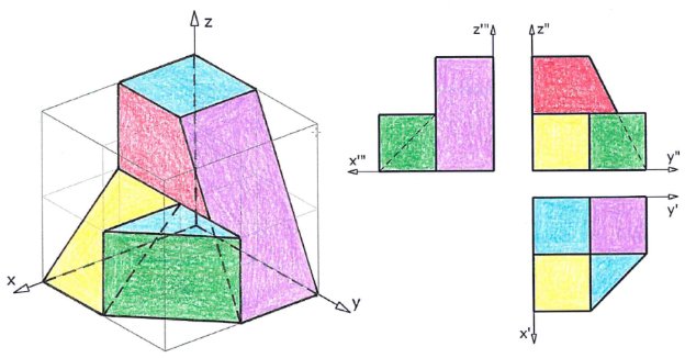
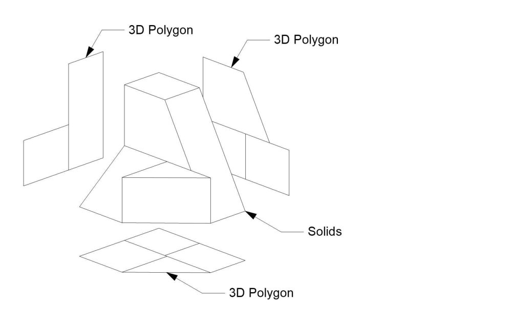
Let me start with this picture (found on the net, descriptive geometry, highschool class): Quite simple to produce this with Vectorworks, for example by using the 'create multiple viewports' command, You will get a sheet layer like this: But what if you have a complex drawing and you want a result like this on a design layer ?: The problems that occur are: - sheet layer viewports can not be copied to a design layer - complex drawings produce 2d (hidden line) viewports with multiple overlaying lines - creating a viewport on a design layer does not result in the desired polygons So how to solve this (simple) task? 1.) create a sheetlayer viewport in hidden line rendering of the desired projection. 2.) export this viewport either as PDF or as dwg file 3.) re-import the pdf or dwg file to vectorworks. 4.) ungroup the pdf file or the dwg import results if needed 5.) use the purge command to delete overlaying lines => You will then get 2D or 3D lines or polys that show the projection of the solids on a design layer (depending on the choosen import-export options). I am really wondering If I have overseen a more simple workflow. If not, I am wondering if this is really the way how to work with a cad programme in 2023. Looking forward to any comments and/or solutions from the forum... 🙃

-
Anyone here who uses HP's "Instant Ink" subscription ? Does it have real advantages or ist it just a monthly money collection for HP ?
-
Bought a HP DesignJet T650 24-in 6 Months ago. I call it my 'dancing machine' since it's shaking a lot when printing, but up to now, it works reliable. I think it's mainly designed for small business. I'm printing not more than 80 Sheets per week.
-
Maybe this is a windows issue ? Noticed the same behaviour here: As long as the home screen is active, it is not possible to open a vwx file via double clicking.
-
Visibility Tool - random functionality
halfcoupler replied to DSmith2300's topic in General Discussion
Maybe this is a question of the date the class was created ? A class created after the viewport was created will be invisible in this viewport. When creating a new class You can genrally control the visibility of this class in viewports in the visibility tab of the class edit dialogue: I think these settings are the default settings unless you override them in the viewport settigns. HTH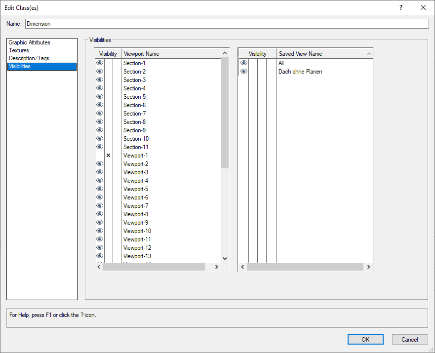
-
I'm not shure, but isn't the Moebius Curve a 180 degree turn ? It seems you made only 90 degrees ?
-
Yes, great work, I wonder how long it took for the modeling? Aluthough some details are missing, I estimate is was not less than 3 hrs ?
-
I have a dream: That some day a picture like this is sent to A.I. and it returns a 3D stage model. That some day A.I. will create a virtual stage out of this. That some day virtual artists will perfom on this virtual stage. That some day A.I. will fill the virtual seats with virtual visitors. That some day A.I. will write reviews of the concert. That some day, from out of my grave, I will never realize what a wonderful a concert I have missed.
-
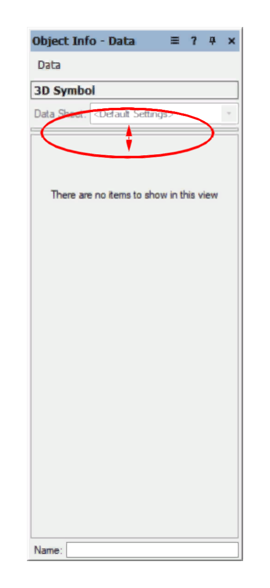
Hi Bruce, I think I know what happened, since I once stumbled over the same thing: Maybe Your data tab of the OIP looks lke this? Then you need to expand the middle window. I dont know what makes VW to hide these fiels sometimes (I suppose it's after an update was made), but when you don't know that the settings are hidden there, you are lost...
-
Absolutely agree, but let me try to make a really long story short: The best way to get a first understanding of how the data manager works is to consider the hirarchy of object data in VW: - Changing data of a symbol instance will overwrite the setting of the data the instance may have inherited by the setup in the Recource Manager. - Changing data setup of the of the symbol in the Resource Manager will overwrite settings this symbol may have inherited by the settings in the Data Manager. - Changing settings in the data manager will only effect data of a symbol that is newly imported without having any settings already 'hardcoded' in your document. Settings in the Data manager are some kind of 'pre programming' to fill up empty symbols with data a soon as they are imported to the file. Consider the symbol as a shopping basket that is automatically filled wit noodles as long as there are no noodles inside. But it may also be filled with rice althogh there are already noodles in the basket if the data manager sais to do so. It took me a long time to understand this hirarchy, I always thought it was the outher way round and wondered why changes in the data manager took no effect to may library symbols which already all have recordsets and data attached. Hope this helps that others do not tap into this trap.
-
Import Large / Heavy DWG to a manageable size
halfcoupler replied to Jason-Baeri's topic in General Discussion
I have stumbled over this so many times and have spend so many hours on this. It is not a really Vectorworks problem, since you can't know what to filter unless you have opened the file. What you need is: 1. Patience 2. Coffee 3. more Coffee My Workflow proposal: 1. Don't think this is a 5 minutes issue. 2. Try to chose as meanigful import options as you consider this file should have. 3. Press IMPORT 4. Go to sleep, or have a walk with yor dog, or go jogging, or do similar that calms you down for the next hours. 5. Come back to you computer someday to look if it's finshed importing. 6. If its finished, backup the file, since the next step could ruin your work. 7. Try to run the purge command, especially try to delete all coincident objets. This may work quite well (especially with 2D files), but it may also throw the baby out with the water. If thats the case , carry on with the backup. 8. Take a look at the class structure and imagine which could be the class with most items. 9. Switch this class to invsible. 10. Have a coffeebreak 11. If you have accidently chosen the class with the most items, you may need more coffee. 12. if you have accidently chosen the class with the lowest count of items you may need less coffee. 13. repeat steps 6 - 9 until the file gets managable (for example the flyover tool starts working) 14. export the 'big classes' to separate VW files and work on them separately. Then import or reference them back to your file. 15. The only option to get the file smaller and more manageable is to delete all things that you dont need for your work. What I forgot to mention: Step ZERO: Try to find out the origin of the dwg file first. Not only one time that I later fout out: The huge dwg file was an export from a Vectorworks file.😁 HTH 🙂 -
works perfect ! thank you for teaching me VS 🙂
-
Yes, thats hardcoding the Worksheet Name, but I want something like: VAR: ExportFilename : String BEGIN ExportFilename := GetTopVisibleWSName ; PutFile('Choose or create file for export', ExportFileName, FName); But I don't know the correct expression for "GetTopVisibleWSName"


