Carrie C.
-
Posts
11 -
Joined
-
Last visited
Content Type
Profiles
Forums
Events
Articles
Marionette
Store
Everything posted by Carrie C.
-
Lights are showing black and not white when on
Carrie C. replied to Carrie C.'s question in Troubleshooting
@klinzey Thank you for the help and explaining why I am having this issue. CC -
Lights are showing black and not white when on
Carrie C. replied to Carrie C.'s question in Troubleshooting
Yes, I've dropped in the file and have left everything to default mode. Test Help.vwx -
Lights are showing black and not white when on
Carrie C. replied to Carrie C.'s question in Troubleshooting
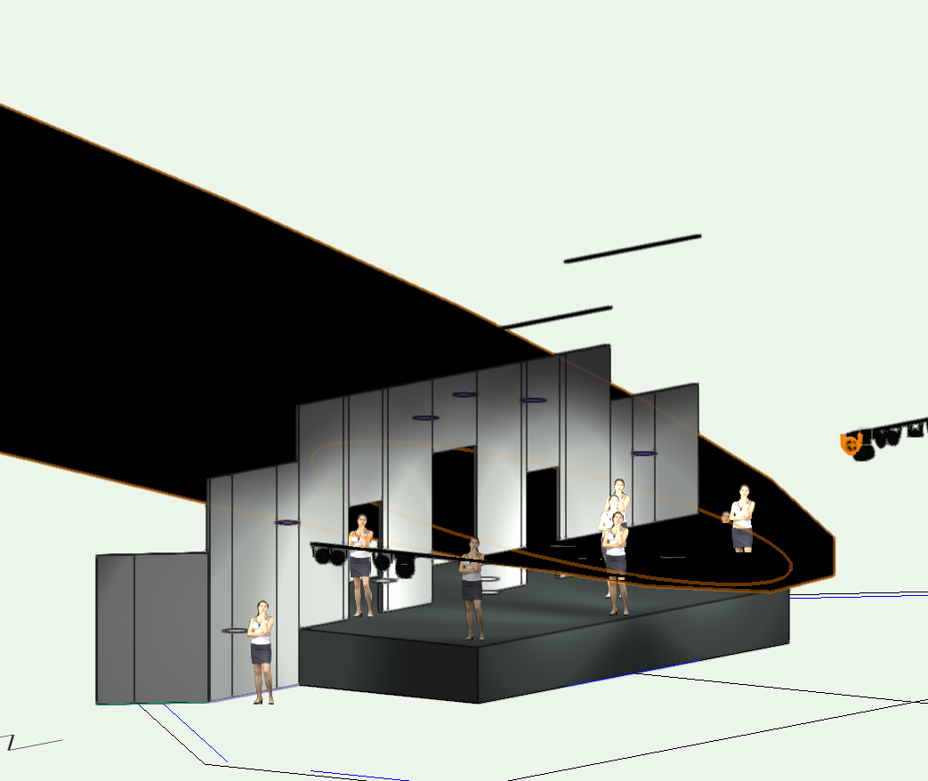
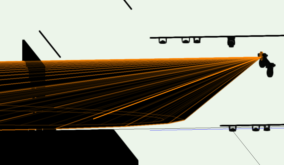
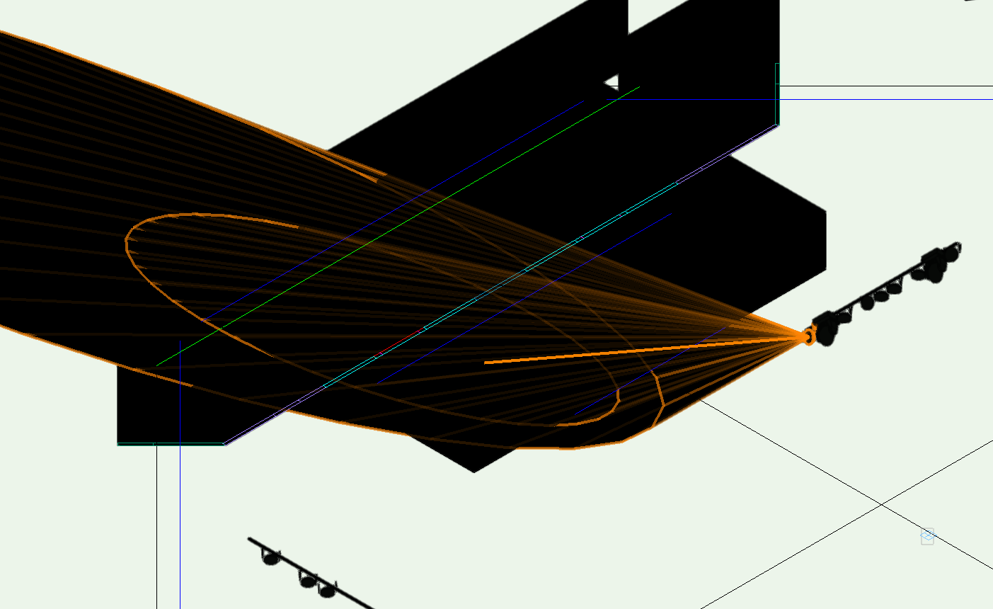
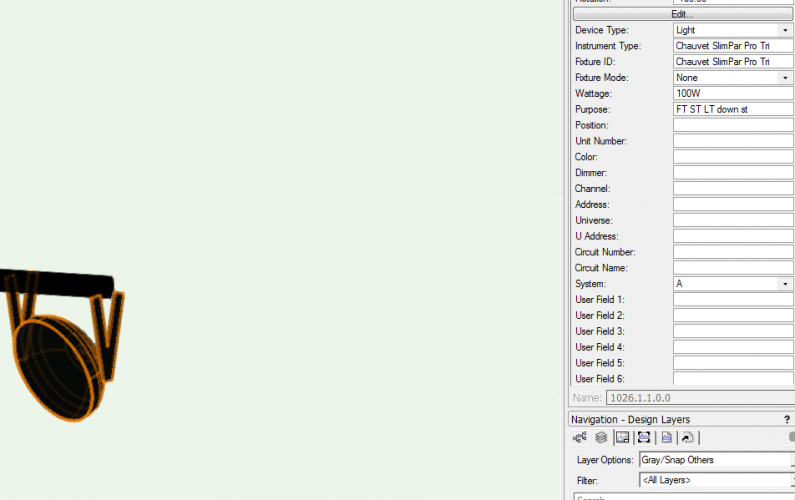
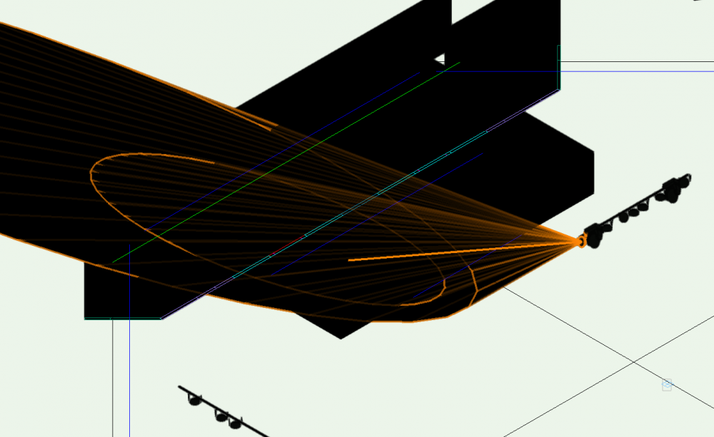
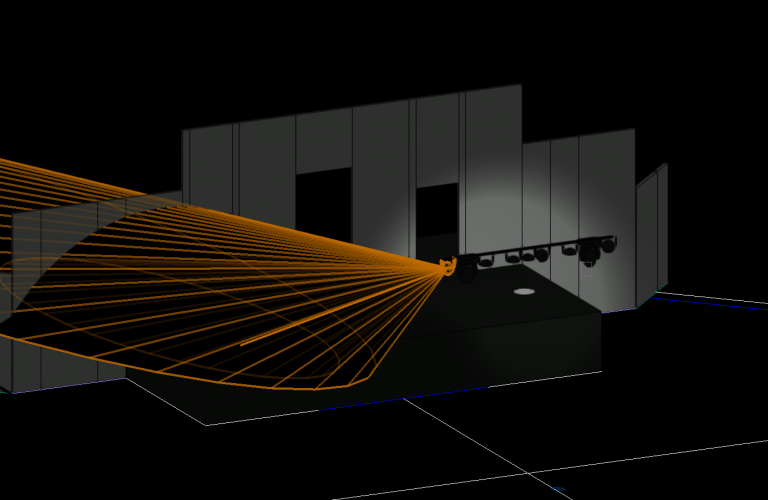
Rob, I apologize if I am or was confusing in my search for help, however, yes, I am using the VW light default symbols from the library and I am using the default lighting instrument texture. As you can see I now have lighting on the set, but the 3D solid beam feature still shows black when turned on. I'm using the Chauvet Slim Par and I was thinking I just need to adjust the pen and or fill attributes? I'm not sure if it helps explain the issue better or not...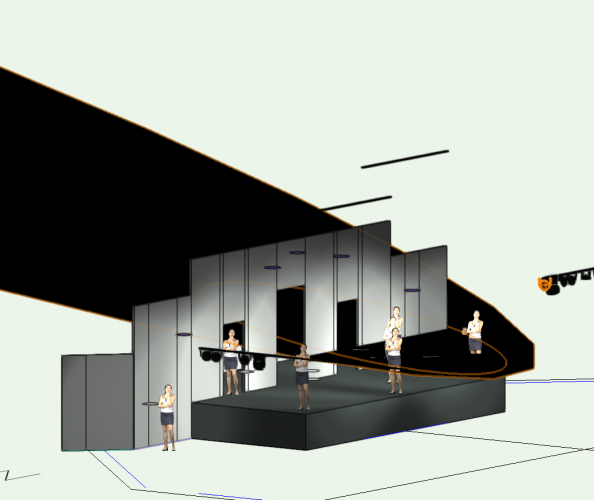
-
I really need to get to know this program better, however, how do I get my lights to shine white instead of black? I usually, have a black background and this has not been an issue in the past versions. Once the light is turned on and a focus point is set you can see what your set piece would look like with your lights focused. Now, all I see is black light which is not helpful and I thought maybe I can do a fast render to see what the lighting looks like but sadly that did not help either. I have changed the attributes colors to white which which you can see on one part of the set is "light" but the other is black from having the draw beam and draw beam 3D options on. How do I fully fix this?

-
So back again, how can you change the size of the instrument summary box to a readable scale? Currently, it's as big as a thumbnail. CC
-
I have all my lights on one layer and one class and still no labeling is visible.
-
So, as it is I am on a deadline and I have seen the tutorial on the Label Manager. I can't seem to get the information to show on my plot and I do not have any attributes such as channels, purpose, etc. showing either. I have built each fixture with these attributes but for some reason or another it is not showing up. What am I missing? CC
-
Thank you Kevin. To answer your question, yes they are two separate VW files. I tried cutting and pasting like I would in AutoCAD into the VW file and when that did not work I went to importing into the scenic file and then voice versa into the RCP file. However, the new VW file that contained the whole theatre RCP I imported from a dfw file so I don't know if that had anything to do with why the scenic file was smaller or not when I tried to import it into he RCP file. I did look to see if the scaling was different between the two files and it didn't seems so but I will try your steps next to see if this resolves the issue. Thx, Carrie
-
I am having an issue with trying to combine two separate files into one. I have one file that the set was designed on and and I began to apply lighting to, however it did not contain the whole theatre. The second file contains the whole RCP of the theatre and the building is built in 3D in this file. I now would like to combine the two files together so I do not have to start over applying the lighting. The first file when brought into the second is very small, is this because the measurement was not set in the second file as it is in the first? I tried using the CAD way of importing the two files with no good results either it is to small or it disappears. What can I do to bring these two together?
-
Thank you Benjamin for the advice and clearing up the two. CC
-
I am new to Vectorworks so forgive me if this has been answered though I have looked and not found one. I am using the Focus Point Tool and setting the Focus Point shape I used the default setting, however it show’s (and I can’t show you the entire list but I have the attachment) focus 5ft circle or square, 7ft circle or square etc., 8ft circle or square, and of course the standard hybrid, 2D & 3D, and locus points only. Is this only referring to how the Focus Point is being displayed or is it what is being shown for the beam and field size? For example: I'm use to manually calculating the size of the beam and field from the distance of a fixture to the object. When I use an ETC 26 deg for example in the default mode meaning “standard hybrid” is this showing me the "actual" coverage (of course at what height I set) of this fixture? Or do I need to go back and set the perimeters? Also, I was wondering about the falloff distance; can someone tell me if I have this right. Is it where the light begins to reach its furthest point and you can cut the beam off? Lastly, what is locus point? Please by all means if there is an index I can use other than what is being provided by "Vectorworks Help" I would be happy to be pointed in that direction. Thank you for your patience. CC