


MarcU
-
Posts
41 -
Joined
-
Last visited
Content Type
Profiles
Forums
Events
Articles
Marionette
Store
Everything posted by MarcU
-
dwg-import unifies individual directions of hatches instead of preserving them
MarcU replied to MarcU's question in Troubleshooting
Thanks Jeff for your analysis and time. The file is an export out of archicad by some other architect. So unfortunately I don't have any way to influence that... Seems like I have to readjust everything manually. -
When I import this dwg in to Vectorworks, the object-specific directions of all the hatches are not preserved as they should be. Instead they are unified to one direction/alignement. Since in this case the hatch direction indicates the direction of the roofes, preservation is absolutely necessary for me! Otherwise I would have to readjust all of them manually... The dwg is definitly fine. I checked it with an Autocad-clone. Thanks for any help! Dachaufsichten.dwg
-
Best way to set working plane perpendicular to a linear object?
MarcU replied to MarcU's question in Troubleshooting
Thanks Grant I find the 3-Point method not very intuitive and complicated since I would have to turn the plane in to position in a second step. SketchUp works so much more user friendly and fluent in this case. Happy Easter Markus -
Best way to set working plane perpendicular to a linear object?
MarcU replied to MarcU's question in Troubleshooting
Thanks! This was new to me, helps and is a good step forward. But: it only works with NURBS curves (which I had to find out first by trying long...) It does not work with 3D-polys and solids/meshes. So It would be great to have some ctrl-alt-shift combination to switch to "perpendicular mode" independently of the type of linear object. Markus -
For the "set working plane" tool I suggest an aditional 3-point method: - first click = i.e. start point of a linear object/edge to be used as a rotation axis = origin - second click = end of this linear object/edge = define direction of z-axis - third click = somwhere else = define direction of x and y axis What you get: a working plane perpendicular to the the linear object or edge. Or even better: the rotation tool should have an option to define the rotation axis by two clicks on the linear reference object / edge and a third click to start the rotation. Currently the rotation tool can only align automatically to existing planes, but not perpendicular to existing linear objects or edges. Go see i.e. rotating in SketchUp: there you can align the rotation tool perpendicular to the rotation (z-) axis by click-dragging in the direction of any linear object/edge. What do you think? Thanks for supporting these whishes.
-
Best way to set working plane perpendicular to a linear object?
MarcU posted a question in Troubleshooting
Hi the set working plane tool has only two methods: you can align it to a surface or you can use three points to define it. In many cases, I want to look in the direction of a certain line in 3d space (the edge of some object or just a segment of a 3d poly), especially to rotate objects around a line, using the line as an axis. So I would have to set the working plane perpendicualar to the axis. What is the best way to achieve this? Or are there other ways to rotate objects around existing linear objects in 3d? Thanks for any help. Markus -
3d Image object does not display in section viewport
MarcU replied to MarcU's question in Troubleshooting
thanks Jim and sorry. Things work now. Don't know why it didn't before... -
Is it possible to display 3d image objects (like png trees which face the viewer automatically) in section viewports? I can't geht this working. Am I missing something? If this doesn't work, does anyone have a workaround? Placing them in the annotation space is not really a solution. Why do they show up in normal viewports and not in sections? Thanks for any help. Markus
-
=IMAGE function is better, but...
MarcU replied to ericjhberg's question in Wishlist - Feature and Content Requests
1. I would also highly appreciate a better image of the worksheet graphic function. It would be great to insert symbols as original vector graphics instead of raster images. This would solve all graphic problems. Line thickness is not represented correctly 2. for display of the graphic attributes I would want to be able to controll the shape of the representation: when I want to display classes without fills (in a legend/schedule) I just want a horizontal line, not a whole square. Also the scale of the representation I would like to be able to controll. This is not possible. 3. Horizontal line objects with complex linetypes are not displayed correctly in worksheet: only the actual base line part is shown (see attached png) worksheet test.vwx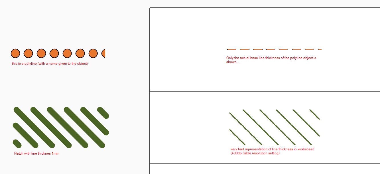
-
Duplicate Class - Option to rename/edit
MarcU replied to Itchy's question in Wishlist - Feature and Content Requests
Had the same Idea for long. Would be great! -
Drawing Label wishes
MarcU replied to michaelk's question in Wishlist - Feature and Content Requests
I would suggest to totally redesign the drawing label tool so it works somehow the same way as the title block tool. Then every field and graphic element could be controlled individually. -
Hi at the moment I do not see any possibility to controll the exact size of an image fill in a global manner: there is no way to define the length and width (i.e. in meters, but not pixels) of image fill definitions in the resource browser (like for renderworks materials or like for materials in SketchUp). I can only change width and length of the image on an object level in the attribute palette. This means I cannot overwrite the appearance of an object in a sheet layer, if its properties have allready been overwritten in a construction layer. Therfore my urgent whish: image size (in real world units) of image fills should be controllable: a) on a global level in its resource definition in the resource browser b) on a class level But: there is a workaround: replace the image fill by a tile fill: a) draw a square tile in the size you want your image and fill it with the desired image fill b) adjust the image fill width and length of this square object to the same size as the square c) create a seamless scale-dependant tile fill of this square and use it instead of the original image fill. What do you guy's think? Thanks for supporting this request. Markus
-
Realistic Road/Grading Tools ??
MarcU replied to nca777's question in Wishlist - Feature and Content Requests
I totally agree. The vwx road tool has nothing to do with reality. I wonder if it is ever used. Same thing with the hardsape tool. Has anyone seen a completely flat hardscape in the real world? -
Mirror + alt = mirror copy
MarcU replied to VincentCuclair's question in Wishlist - Feature and Content Requests
I would also highly appreciate these features. I could also be ctrl or shift for me, I wouldn't care which. The Move tool works similar for me allready: I use it for allmost all duplicating jobs with reference point, just by holding down ctrl. The U-key thing I also pretty clunky. It is all about having a standard setting (i.e. no duplicating) and controlling duplicating by temporarily holding down a key, like as mentioned above in Adobe. -
I agree, but: A simpler first step enhancement of fillet and champfer in VW would be a re-fillet and re-champfer function, means: that allready champfered / filleted corners of polys could be champfered/filleted again with another value. Setting this new value to zero would be un-fillet / un-champfer. This is how AutoCAD does it since its existence. I do not understand why VW does not have this simple functionality.
-
Great suggestion!
-
This would be very helpful. I am just working on a document with almost 100 classes from several project partners. It is very hard to find topic-specific classes without a search function.
-
Improve the floating data display?
MarcU replied to barriescott's question in Wishlist - Feature and Content Requests
I understand the logic, but it would be very useful to be able to tab into the floating data bar, not to edit values of course, but only to copy them for further use (i.e. object creation). Values could stay greyed out. See also this thread: https://forum.vectorworks.net/index.php?/topic/40886-tape-measure-tool-send-to-clipboard/ -
Curvature and Surface Analysis like in Rhino
MarcU posted a question in Wishlist - Feature and Content Requests
Hi Vectorworks. Are there any curvature and surface analysist tools like in Rhino planned for the future? They would be very useful/needed for CAM tasks with organic shapes/solids. This is what Rhino provides: http://docs.mcneel.com/rhino/5/usersguide/en-us/html/ch-09_curveandsurfaceanalysis.htm Thanks in advance for any answer. Markus -
Tape Measure tool - send to clipboard
MarcU replied to Mike Wright's question in Wishlist - Feature and Content Requests
Thanks Alan. I needed some time to get your G-key method. Very handy, works perfect for my needs! Great (far better!) alternative to the tape measure which I used for single (not cumulative) distances mostly anyhow. I was unaware until now that you can copy values from the floating data bar with ctrl-C when the desired value is selected with TAB. The problem with the tape measure tool is that you can't get inside the floating data bar by hitting TAB. So it would be the actual improvement to make this possible. Then we could choose between single and cumulative distance to copy to clipboard. At the moment I think we have to state that the tape measure tool is in the developement stage of a mechanical typewriter or older since we have to write down measurments on physical paper... Hope this feature is coming soon. In the meanwhile I will use Alans super-G-key. I suggest Alans method of copying single distance measurments to the clipboard to be implemented in Vectorworks help in the tape measure section as an alternative. To illustrate Alans method here a screenshot: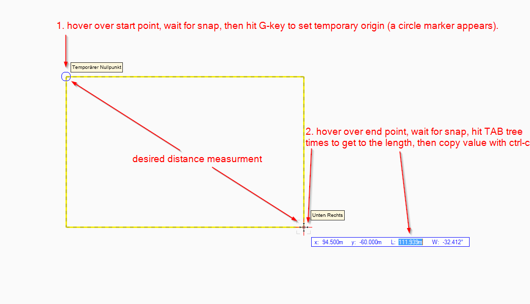
-
Wow! Awsome, DomC! Thank you very much for this tremedous load of very handy nodes (and of course for your earlier numerous contributions to the community)! I'm looking forward to using them! And by the way - thank you for your great Marionette presentation at the Vectorworks Anwendertag in Zürich - it motivated me to get more into Marionette. Have a good day.
-
Tape Measure tool - send to clipboard
MarcU replied to Mike Wright's question in Wishlist - Feature and Content Requests
totally agree! I just wanted to suggest the same thing and then found this thread. -
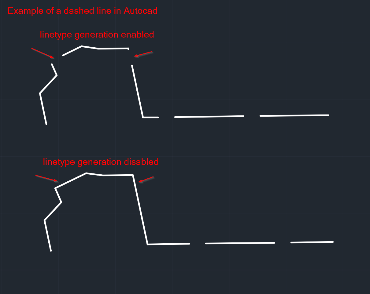
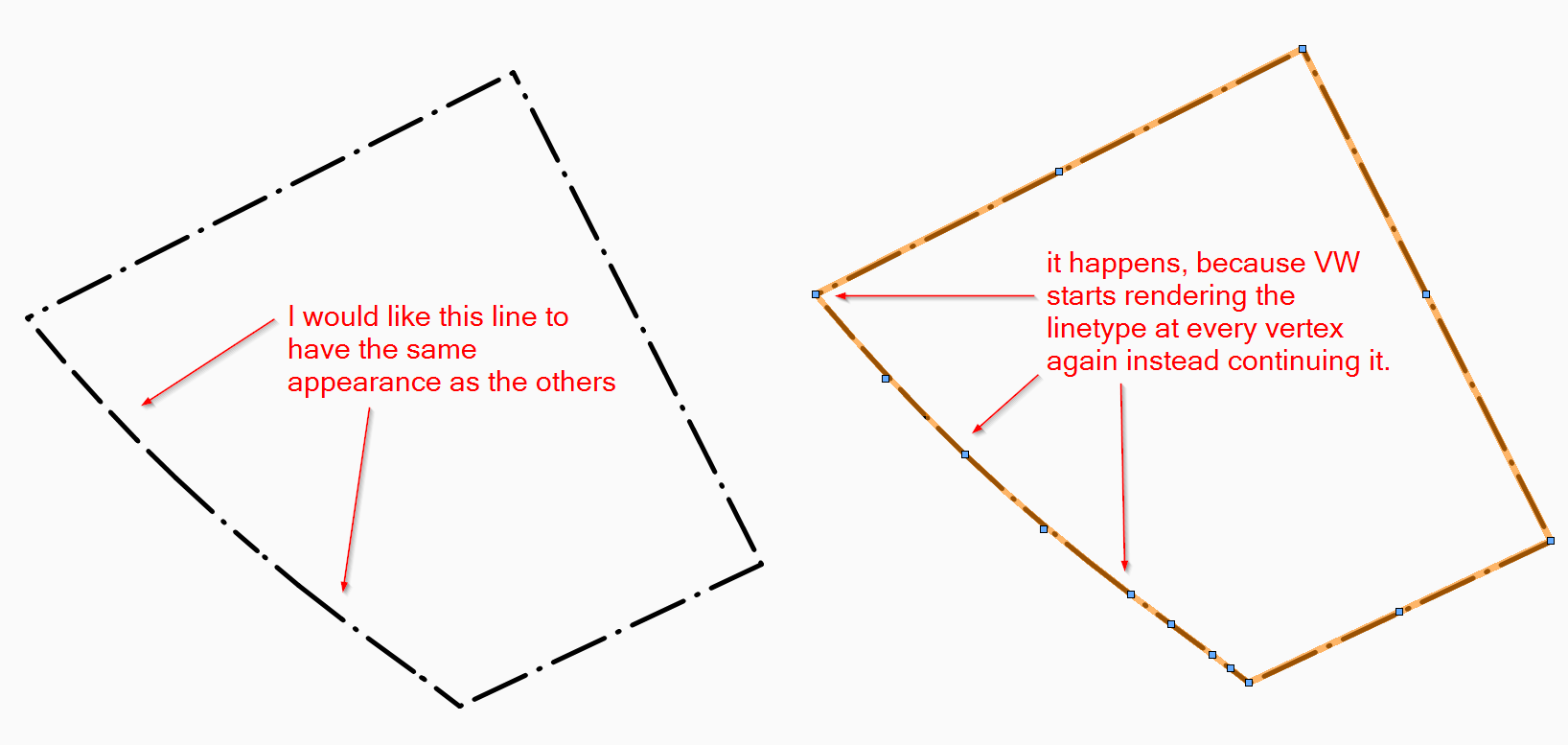
One of the few things I liked in AutoCAD (I was forced to use it some years... ) was an object-attribute called "linetype generation" which you could enable or disable for any linebased object. Enabling would take the pattern of simple dashed/dotted-dashed linetypes PAST vertices instead of starting the dashing pattern newly at every vertex as when disabled and as Vectorworks does it. You get it? See the attached screenshots which illustrate the feature. It would be great to have this in VW as well. Of course either mode has its advantages and disadvantages: a) if you have sharp corners and you have linetype generation enabled, it may happen that you have no line at the corner (if the gap between two dashes is there). b) On the other hand, if you have curves or obtuse angles (like in the second screenshot from VW), you will get a bad looking appearance of dashed and dashed-dotted lines. I imagine this as a checkbox in the OIP - something like "continue lintype at vertices". Thanks in advance for considering this as a future feature of VW. Markus
-
Thanks Benson and Allen Sorry, system/vwx specs were inside the vwx file in the instruction text, now I added a signature, see below - thanks for this suggestion. Thus I don't think it is my graphic card which isn't that bad. Yes, turning auto rotate off makes textures visible again. But I need rotating textures, anywhere, independent of their position in the coordinate system. A fiew hundred meters is not much, I find. anyway - JimW confirmed this issue as a bug VB-138160 in this thread: https://forum.vectorworks.net/index.php?/topic/47487-3d-plants-image-props-not-showing-up/ So hopefully this problem can be solved soon.
-
Great! You're pretty fast, thanks! looking forward to that.
