


SBarrettWalker
-
Posts
335 -
Joined
-
Last visited
Content Type
Profiles
Forums
Events
Articles
Marionette
Store
Everything posted by SBarrettWalker
-
 Hello, There is a node in the Operations folder called the Orient node that allows you to set the z- axis of an object based on a 3D vector. I believe this will work for you based on the parameters you already have. Here is an example file. OrientNode.vwx
 -
Version 2.0.0
1,168 downloads
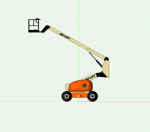
This is another Marionette object based on a symbol belonging to @barnes2000. (Thanks Scott!) He has built a bunch of cool crane and lift symbols. This one is an Articulating Boom Lift that has seven different rotation or extension articulations. Each has a Slider in the OIP that allows you to set its angle or extension. (See video.) This Marionette object works by placing the different parts of the Lift as symbols in the drawing at a particular insertion point and rotation based on the values of the Sliders. Each symbol has named loci that are used to locate the object in the drawing space and in relation to the other parts. The loci are on an invisible class (so don't delete the class from the drawing). The object updates pretty quickly for having so many variables. If you wish to share the object to another file, make sure that you import the entire symbol folder. Unlike the Scissor Lift, this object is not built from hybrid symbols because hybrid symbols cannot be rotated around the x- or y-axis. If you wish to convert it to a hybrid object, you could place it inside an Auto Hybrid, but this will make it a much bigger object (memory-wise), and you would only be able to edit the object from inside the Auto Hybrid. -
Version 3.0.0
1,362 downloads
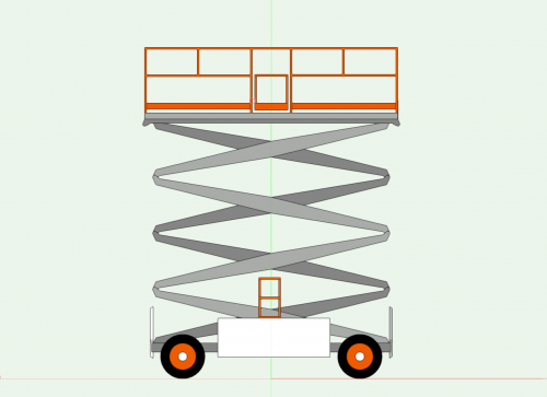
This Marionette object is a Scissor Lift PIO. You can place the Scissor Lift in your drawing and set the height via a Slider in the OIP. (See video.) All the different parts of the Lift are different symbols, and the Marionette script places each symbol at a particular insertion point and rotation based on the value of the Slider. If you wish to share the object, make sure that you share the entire symbol folder that holds all of its accompanying parts. This object was based on a symbol created by @barnes2000. Thanks Scott for letting me play! -
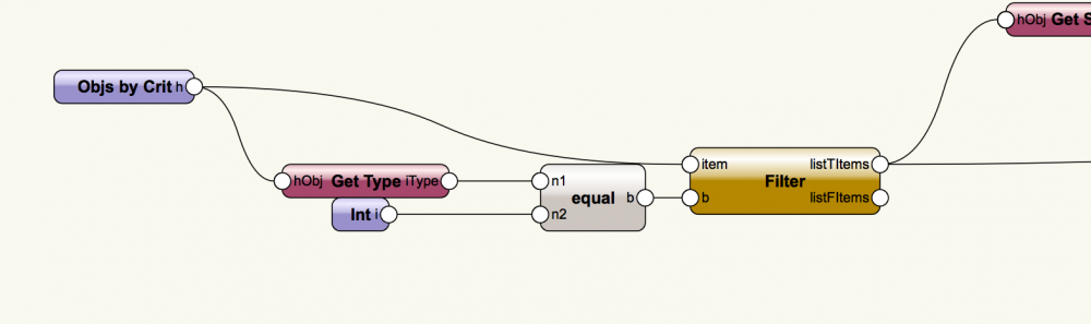
Hello Martin, To answer your question about filtering - you can filter by object type. You can find a list of Vectorworks object types here: http://developer.vectorworks.net/index.php/VS:Function_Reference_Appendix#objects I have added a section that filters by object type to your network. I find this little network to be very useful - changing the value of the integer changes the object type you are looking for, but you can also change the Get Type node to another Get Object Info node that gives you a number value and the Integer node to the appropriate value you want to match it to. Autonumber_ID_sb.vwx
-
List Explode - local variable 'rest' referenced before assignment
SBarrettWalker replied to HebHeb's topic in Marionette
I just checked the network I sent and I forgot to connect a node. It now works so that each extrude takes the class of the corresponding profile. Essentially, each input is a list of objects or a list of classes, and it applies the class from the class list to the corresponding object in the object list, so you don't need a separate EAP node, you can use input lists of matching lengths. Profilsymbol_am_Pfad_sb.vwx -
List Explode - local variable 'rest' referenced before assignment
SBarrettWalker replied to HebHeb's topic in Marionette
In looking at your network again - you don't actually need the list explode node. You are performing the same operation on each of the objects so you can send the whole list into one Path Extrude node. I made some changes to your network based on this, including duplicating the curve for every element in that list and sending them to the same node. Let me know if you have any questions. As a rule, I try not to repeat nodes when I don't need to, especially inputs. Profilsymbol_am_Pfad_sb.vwx -
List Explode - local variable 'rest' referenced before assignment
SBarrettWalker replied to HebHeb's topic in Marionette
Hello, Does the error persist? are you able to rerun the network/create a Marionette Object on subsequent attempts? I know there was an error in the code of that node that was fixed recently. When I tried your file, I got that error once but it didn't persist. I can see from the network though that the Delete node attached to the List Explode node will be a problem - if there are no objects going through the wire to the Delete node, it will produce an error. Detaching the Delete node shouldn't change your network. If you do want to use a Delete node in the future, I would recommend the modified Delete node in the file I attached. (This modified Delete node is only a stopgap until the default one is changed.) HTH -Sarah Delete.vwx -
Whenever you change the code inside a node, you should first delete the very first line of code that starts: #COMMAND; This line creates a link between a text file and the node so nodes can be updated with new versions of Vectorworks. Deleting this line breaks the link, similar to ungrouping a symbol, allowing you to edit the node without affecting others. You can then save it as a plug-in object to use again later. Best of luck!
-
The Get Font ID node allows you to set a font by giving the name of the font, or you can create a Text Style in Vectorworks as a resource and access it in your network by using the Set Style Ref node.
-
I have added another version of the node that has an input instead of an OIP input. I also simplified it (I removed the aspect of overriding the document units). To create a pop up menu to choose symbols is definitely possible - it involves a tiny bit of coding though. There is a Popup node in the Input folder, and it allows you to create a popup list if you double click on it and follow the instructions in the code. The output of the node is the index of the list item chosen, so if you have a matching list of strings elsewhere in your Marionette network than you can use a Get Item node and the output of the Popup node to access the correct string. To delete an object based on a True/False value, you can use a Valve node in the Data Flow folder, which allows you to block aspects of your network, or you can use a Filter node and my version of a Delete node - I put examples of how they work in the new Format Units file. FormatUnits.vwx
-
In order for trailing zeros to show up, the number must first be converted to a string - I have written a node that converts numbers to strings as well as adds document units, its called Format Units. I have added another node to the file that does the same thing except does not add the unit abbreviation. HTH FormatUnits.vwx
-
Marionette Node Object Text Label only visible in 2D view
SBarrettWalker replied to Benny Franke's topic in Marionette
Hello @Spotbenny- I think this has to do with the difference between a Marionette Object and 3D geometry in Vectorworks - a Marionette Object acts like a hybrid symbol, so 2D objects have to be converted to 3D to display outside of Top/Plan. To do this, you can convert your text to polys and then convert those polys to 3D polys. I think that will work. There is a node in the Objects - Text folder called Convert to Poly Group, I believe. -
Thanks all!
-
Hello all, is there an easy way to find out if an object is a 2D or 3D object? I feel like there has to be some sort or properties call but I am not aware of it. I need a way to filter objects in a script by whether they are 2D or 3D, but all I can think to do is filter by object type, and that seems way too involved. Thanks!
-
Here is a custom node that might come in handy: Compound List. I use this all the time. CompoundList.vwx
-
If it helps, Here is a color input node that allows you to get rob values based on the fill of the node. I have attached it in Vectorworks 2017 and 2018. 2018: ColorInputNode.vwx 2017: ColorInputNode2017.vwx
-
 Hello @ericjhbergI thought I responded to your comments earlier but I can't seem to find what I posted. 1. Is there any way to make the horizontal curvature more regular? I know this is using nurbs, so the answer may very well be no, but we often are trying to design ramps on a radius which is difficult to do accurately with nurbs or bezier curves. - In order to make this path based (allow it to have control geometry that was editable with the reshape tool), I found the easiest way to accomplish it was using a Bezier curve. To write it using a poly with arc vertices would be a very different script. How would you draw the 2D profile of a ramp? 2. The cross slope profile created by the loft surface can create some pretty extreme cross slopes. Is there a way to better control this? - I built the ramp by dividing each edge length equally and stepping it that way, I didn't know how to best calculate slopes for ramps. for stairs it is a matter of finding a tangent to the curve but with a ramp I imagine you want you slope to be shallower going around curves and steeper on straightaways. Any pointers on how you would model this would be greatly appreciated. Maybe even starting with how NOT to do it is helpful.
 -
Version 1.0.0
361 downloads
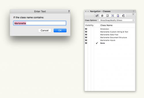
In Vectorworks 2018 menu commands can now be created with Marionette. To create a menu command, right-click on a wrapper and select Convert to Menu Command, and give the menu command a name exactly as you would like it to appear in the menu. After it is created, it will be available under Tools > Marionette Commands > [Command Name]. This command works as a simple find and replace command for class names. It makes use of a User Interaction node which allows you to enter text while the command is running. Once you run the command, in the first dialog box that pops up, enter the text of class names that you want to replace. In the second dialog box, enter the text that you want to replace it with. If there is more than one instance of the text in the class name, it will only replace the first instance. To change more than one instance, simply run the command again. If you make an error, you can simply use the Undo command. -
Version 2.0.0
499 downloads
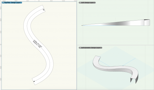
This Marionette object is a path-based ramp. The path is a bezier curve and can be reshaped by double-clicking on the object. The 3D ramp is built by lofting NURBS curves and the 2D text can be turned on or off in the Object Info palette. This ramp uses the new Valve node in Vectorworks 2018 which means it can't be exported back to 2017. -
Hello, Its hard to know exactly what is happening based on images. If you could share the file that would be much more helpful. The things I notice in the image of the script are 1) I am not sure why there is a Mix2 node - it seems like you are just trying to create three curves based on an original and two offset vectors but I am not sure without seeing the curves and the values in the script. 2) Your circle is not connected to the network so I don't really know how you want to use it.
-
It looks like the first time you selected the network, a few of the string nodes didn't get selected with it, and the inputs that SHOULD have been connected to are the ones that showed up on the outside of the wrapper. I haven't been able to replicate that however. Your next step could be to start experimenting with the Set Text Properties and Set Character Properties nodes to position and format the text within the box.
-
With Marissa's example, I believe you would have to attach a Delete node as well as the Get String node to the Text node. The reason is that both the Text node and the Print List node are create Text Objects and you only need the one being created by the Print List node.
-
Version 1.0.0
161 downloads
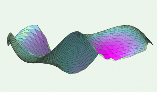
This file was created by Proving Ground to analyze the panelization of NURBS surfaces. Based on 3 NURBS curves, it creates a lofted surface, then converts it to a series of 3D polys. It then compares the 3D polys to the curvature of the surface at that point and states how out of plane each panel is. It also uses a color gradient to indicate where it is out of plane. It then makes a copy of the panels and lays them flat in a grid. -
To explain what is happening in the video, when you use the Text node, you are converting the number and strings of the prefix and suffix to a Vectorworks text object. If you debug the network, you would see that the info going from that list would consist of a Vectorworks handle, and two numbers. What is being printed by the Print List node is the unique name of the handle, not the strings that make up the text object. For this example, I would use a list node to list your prefix, number value, and suffix, then send that through a Str node to create a single string, then add it to the list that you send to the print list node. I hope that helps!
-
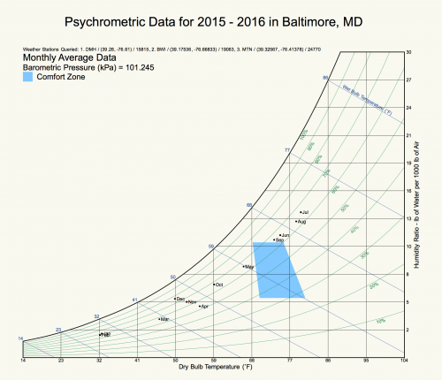 I'm sorry but this file uses capabilities that are not available in Vectorworks 2016, namely importing a Python library. This Marionette object and the other Weather Analysis MOs use an external Python library that gives you latitude and longitude based on an address/location.


