

SBarrettWalker
-
Posts
335 -
Joined
-
Last visited
Content Type
Profiles
Forums
Events
Articles
Marionette
Store
Everything posted by SBarrettWalker
-
 @nealjane1 I uploaded a new version of the file with the date _190228 and it appears to be working fine in 2019. Please let me know if this solves the problem.
 -
@VvierA Can you send us the file?
-
Hi @cberg- Oh, the Space tool. There is a way to do this but its hidden. The parameters of each finish "key" are there in the space but they don't show up in the dropdown menu of the space's object parameters. I am not sure why this is true. I have built a data tag that is set up like the image you provided. I don't believe there is a separate trim finish in the space, only a base finish, so that parameter isn't included, but all the others are. Let me know how this works! Finish Data Tag.vwx
-
From a scripting standpoint, I think you could easily put these objects in separate classes. Putting them in separate layers can be a little trickier, because the created geometry is always placed in a group and that group will be placed on the active layer, no matter what layer the objects INSIDE the group are on. The way around this would be to place your starting objects on the layers that you want them on, and then run your script with the active layer set to the layer that you want those objects placed on. You can do this within the script with classes using the Set Class node from the attributes folder, or with layers using the Set Layer node from the Layers folder.
-
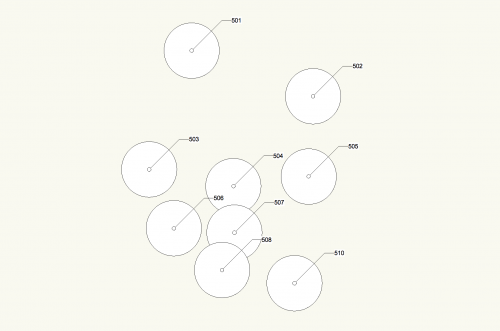
Version 1.0.0
130 downloads
This file is most useful for Landmark users but could be adapted to other plugin objects (PIOs). The purpose of these scripts are to take surveys of existing trees that consist of "dumb" data - pieces of geometry and text to label trees on a survey - and convert it into Existing Trees with the relevant text data associated. The first network, "Test Proximity," runs a check to make sure that each piece of text is closest to its associated piece of geometry. This is necessary to make sure that the second script will work properly. The second network takes the center of each piece of geometry and places an Existing Tree there. It will use the saved red symbol in the Resource Manager as a template, so if you use particular default settings for your Existing Trees, you can edit the red symbol. (Some day maybe there will be an Existing Tree Style!) The network will also transfer the text data to your chosen field of the Existing Tree PIO. In this network, it is set to transfer to the Tree No data field. This network could be adapted to other PIOs if needed.- 1 review
-
- 1
-

-
- landmark
- existing tree pio
- (and 1 more)
-
I noticed that your rectangle nodes are named and when I remove the Int node then those names appear on the outside of the wrapper. To keep this from happening, you can attach a 2D Vector node with the values of 1 for X and 0 for Y to the vRot inputs of the rectangles. Those are the default values for no rotation.
-
Hi @Palle- It looks like you have an integer node attached to the "vRot" input of the rectangle nodes in one of your wrappers. This input requires a vector - that is what the "v" means. It looks like all of the Int nodes you are using have a value of 0 so you are not looking to rotate any of the rectangles. If you simply remove these Int nodes and leave those rectangle inputs open the script will work how you want.
-
You can think of this node as an alternative to the Bool input node. The output of the Yes No Dialog is labeled "b" meaning it is a boolean or true/false value. Yes would be true and no would be false. You can connect it to any node that has a "b" input and some sort of either/or choice. When you run the network, a yes/no dialog will pop up and you can choose Yes or No.
-
The file is a 2019 file - I have exported it to 2018 and posted it here. Popups v2018.vwx
-
I wonder if figuring out whether the church is visible would work better if you project from the other direction - from the church. If you have existing buildings and trees in your model, I imagine that you could create a projection from the church to the location of the building - all the building would need to be is a flat surface - and where the projection of the church hits the surface (isn't blocked by other buildings, trees, etc) is where you know that views of the church exist.
-
I believe it would just be easier to make the multipliers (1,2,3,...) the output of the popup and multiply that output by 12 or whatever variable integer. Again, you can use the Popup node if the multipliers will always be the same, or you can use the Popup Dialog node to have a dialog appear after the script is run. The output of the popups are integers representing the index value of the item chosen from the list. Since your list will basically be 1,2,3 etc you can add one to that integer to get the value you need. I have built some examples for you. Popups.vwx
-
This is possible with a Popup Dialog node, located in the User Interaction folder. The difference between this node that the Popup node is that every time the script is run, a dialog with a dropdown menu will appear, and you will have to pick your option before the network will finish running. If you want a static popup that appears in the OIP of a Marionette object, you still need to use the original Popup node and create the list via editing the script inside the node.
-
In all of the nodes in the default library, there are prefixes for the inputs and outputs that tell you the type of data coming in or out of the node. s = string n = number i = integer (whole number) h = a Vectorworks object, such as a piece of geometry b = True or False p = point v = vector item = multiple value types list = list of items These aren't all but they are the most common. When in doubt, match output prefixes to input prefixes when connecting nodes.
-
Wrapping is just a way to package a script. You can wrap a script by right-clicking on a node and selecting the appropriate command. When you wrap a script, the Input nodes that have been given names will appear in the OIP when the wrapper is selected. Once a network is wrapped, you can then convert that wrapper to a menu command or Marionette object.
-
There aren't any specific tutorials, all I can recommend is to take apart the script you have already and try to figure out how they work. There are some layer nodes that you can use too. You can find out the layer of the space and filter it with Marionette. I have attached a sample network to the other one I sent you that does this. The network is not finished as I don't know exactly how you want the filtering to work, but I tried to show you how to implement it. VW Rooms only_NvdS_Marionette2.vwx
-
Yes, its just a matter of creating a filter based on the layer of the object. You can do this with Marionette or you can add a field in your worksheet and query it there.
-
Hello @Mi&D- Here is a video that shows what I mean. I run the script in the video and update the tags so they show the correct info. ApplyAptAreatoSpaces.mov
-
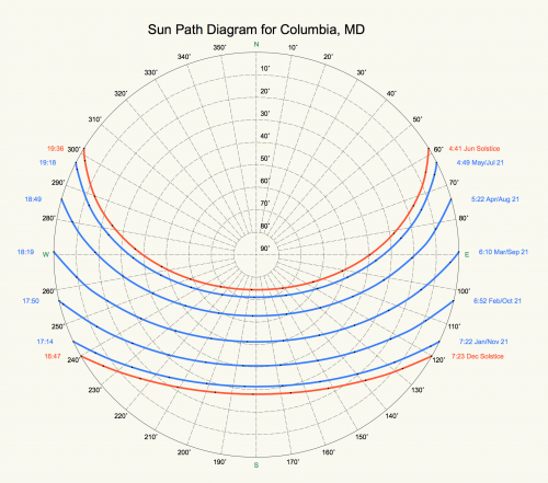 Hello @amcdonell- This is a bug that will be fixed for 2019 in a future service pack. The problem is that with the Mac OS, Apple changed the way that they write file paths, so the command to locate an external library (in this case the geopy library) is broken. This is only a bug for those running Vectorworks on a Mac that is running 10.13 or higher. I also run this OS so I am currently experiencing this bug as well. Unfortunately I don't have any fixes. The script should still work on a PC and on an older Mac OS. This is true for all of my weather analysis graphs.
 -
Sorry I meant to write set up Storys before you set up Layers - this is because you can then use CreateLevelTemplate to create your default story levels as well as have the option to create associated layers at the same time.
-
Hello @C.Miguel- sorry for the late response but I think I have discovered a bug in the story setup commands. I have attached a file that works, but it is important that you set up storys BEFORE you create classes. This is one of the few things that have a set order of operations in Vectorworks. I would also recommend you add in the command CreateStoryLayerTemplate and use that to create your layers, not creating them first and then associating them to a story. The bug I noticed is something to do with units. The document units of the attached file are millimeters, and the command seems to work as millimeters, but if it is set to different document units, it still reads the number as millimeters. I will file a bug but until then I would recommend creating your scripts to set up files using millimeters and then change the document units after running the script. Create Storys mm.vwx
-
Hello @Mi&D I have made a script that I think does what you are asking. It takes the total area from the worksheet and writes it to the Additional Info 2 field of the correct space. It works on all the spaces in the document. I have wrapped the network and given it the name "Apply Apartment Area to Spaces." It works, but the space tags do not update automatically - they have to be "bumped." What worked for me was to select all of the spaces, and choose the correct space label from the dropdown list (even if it is already selected). This will update the tag to show the correct info. VW Rooms only_NvdS_Marionette.vwx
-
@Antonio Landsberger pointed out that the node I made doesn't produce an output in the shortest list mode so I updated it. Here is the updated node. PlanarBoolean.vwx
-
I have created a version of the node that I think might work for you. I have added a dropdown menu that allows you to choose whether to cross reference or to compare lists. For brevity's sake, I only added the option of "shortest list" so if one list is longer than the other, the extra of the longer list will be ignored. PlanarBoolean.vwx
-
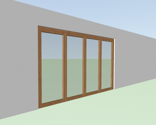
 I did give it a record but I did not attach the actual door record. If you click on the data tab of the object, you can see the fields I gave the record - if you have any other suggestions I would be happy to put them in.
 -
I am not sure if it is possible to tie objects to viewport scale or annotation space, but there is a command that reads layer scale and you can use that to scale your tags if they are being placed in the design layer. I created a node that gets the layer scale that an object is in - if the scale is 1:1, the node will return "1" and if the scale is 1:50, the node will return "50." This was based on the Get Layer node, I just added a command to get the layer scale instead. GetLayerScale.vwx HTH, Sarah