
SBarrettWalker
-
Posts
335 -
Joined
-
Last visited
Content Type
Profiles
Forums
Events
Articles
Marionette
Store
Everything posted by SBarrettWalker
-
I don't think Get Degree get you any useful info. It is a degree of curvature that is specific to NURBS, so it will be a value of 1 if the point is a sharp angle, 2, or 3, etc. for less sharp angles - it is a value that is specific to NURBS geometry and not a real-world degree value. I believe what you are looking for is the Normal value of a Surface at a certain point. There are NURBS nodes that give you the Normal - the direction of the vector that is normal to the surface at that point. You can use this value to orient objects along a surface, for example. I can't remember the exact name of the node or nodes, but it should have the word Normal in either the name or the output value.
-
You can extract a point anywhere along a NURBS curve and get the Z value, but the point has to be relative to the length of NURBS curve, not the coordinate space. Get degree gives you the curvature of the NURBS curve at that point, I don't think it will get you the Z value.
-
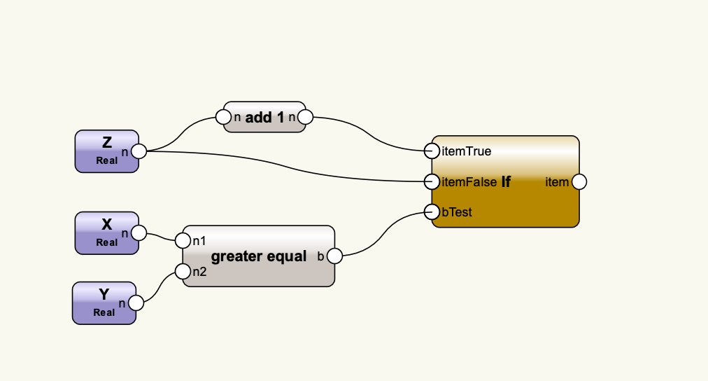
Hello, This is can be done using several nodes in the default library, you just have to build each little equation separately. If Test.vwx

-

Create Story and Level Types without create new Layers
SBarrettWalker replied to KroVex's topic in Marionette
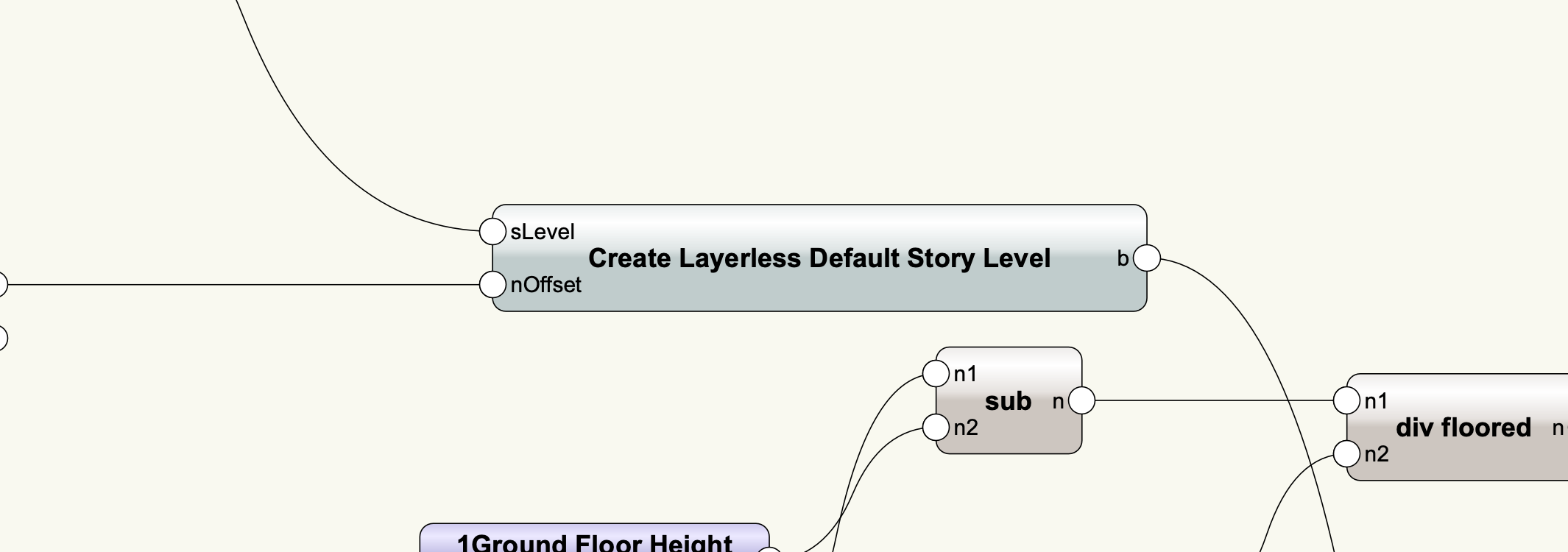
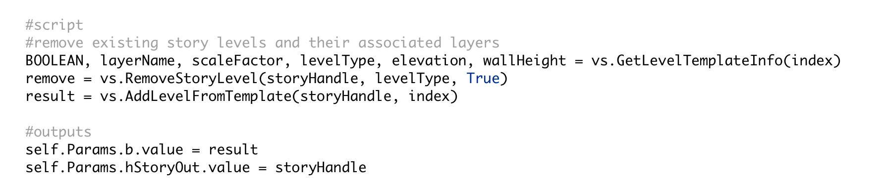
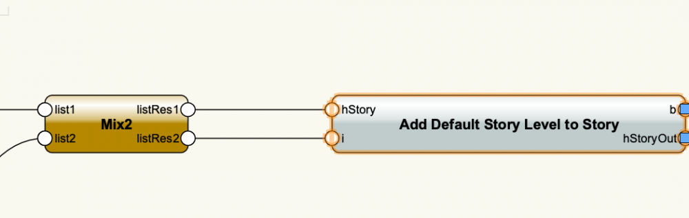
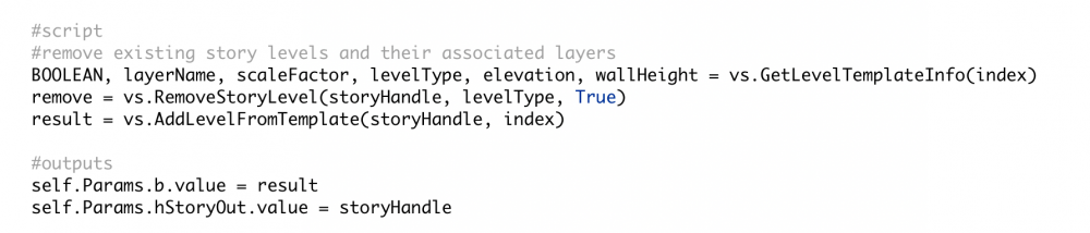
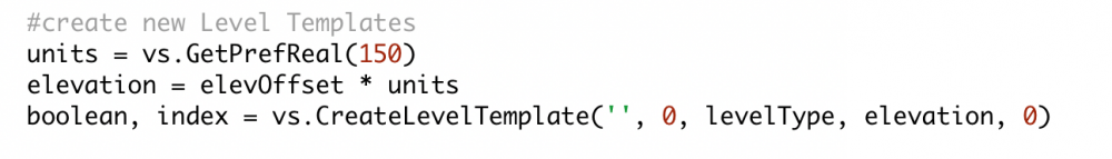
Hi @KroVex In the script that I created, there are two levels that aren't associated with layers in the stories, and to create those I made a custom node that creates default levels that are not associated with layers and then adds them to each story. I did not associate them with a layer after creation. This is the script inside the "Create Layerless Default Story Level" node - I simply used a blank string for the layer name. This is the script inside "Add Default Store Level to Story". If the default level does not have a layer name associated with it, it will not create one when added to a story.
-
Version 1.0.0
107 downloads
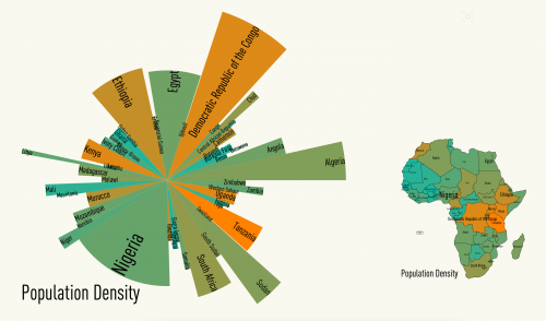
This is an old file that I have recently resurrected. It is one of the first files I ever created and represents my favorite way to use Marionette: infographics. I thought I had posted it here, but I can't find it, so I figured I would post it again. This file contains some custom infographics that I created based off of the polys in this file that have records attached. I have included a second layer that has some chart nodes from the default library. -
The sure way I have found to set the stacking order of objects is after they are created, you put them through an ordered list node, put that list through a group node, and then an ungroup node. The group node puts a copy of each object in the group and deletes the original, so the objects are recreated in the appropriate order.
-
I made some changes to the network. Mainly, instead of having the object sent through lots of different Set Record Field nodes at once, I had them pass one through the other. This may not have been necessary but it seems to have fixed the problem. Also, there were a few of the Set Record Field nodes where the Record Name string was not attached. In order to convert this to a menu command and have the fields pop up (instead of being available in the OIP), you can replace the purple Input nodes with User Interaction nodes. There is a User Interaction folder at the bottom of the list of Marionette node folders. These nodes produce dialogs that pop up every time you run a network. Cavity Barrier-SB2.vwx
-
No, it is not necessary for the particular network you are creating, but if you want to look for specific types of IFC objects, that is a helpful node. The other thing I did was change the info in the Obj by Criteria node. You can't run a network on selected objects, because a node within the network always has to be selected for the network to be run. The only way to use Marionette on selected objects is to convert the network to a Menu Command. You can do this once the network is complete, but while you are building the network, the Obj by Criteria cannot refer to Selection State.
-
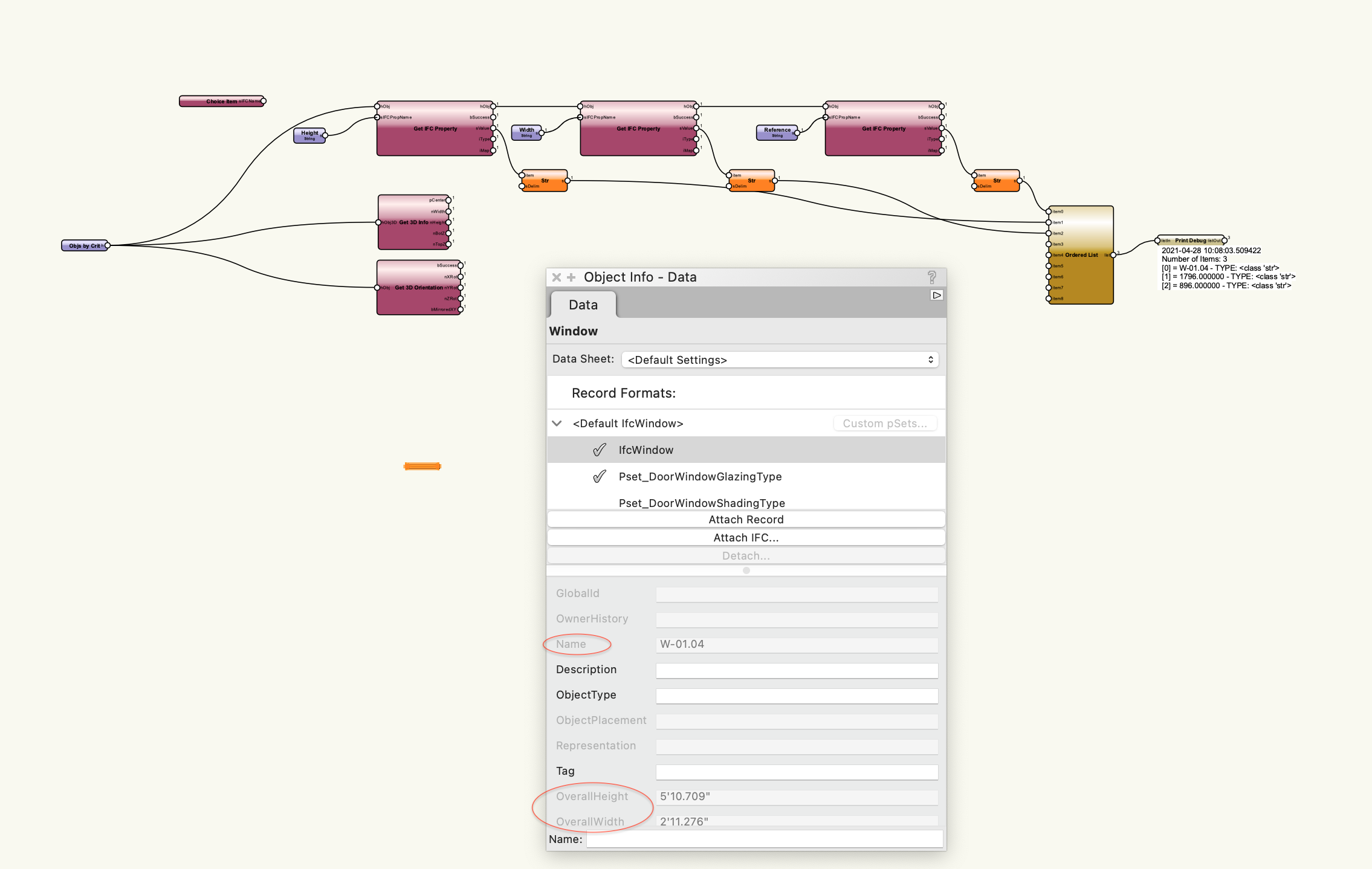
To get the right values, type the field names into the String nodes exactly as you see them here: I have updated the file. Cavity Barrier-SB.vwx
-
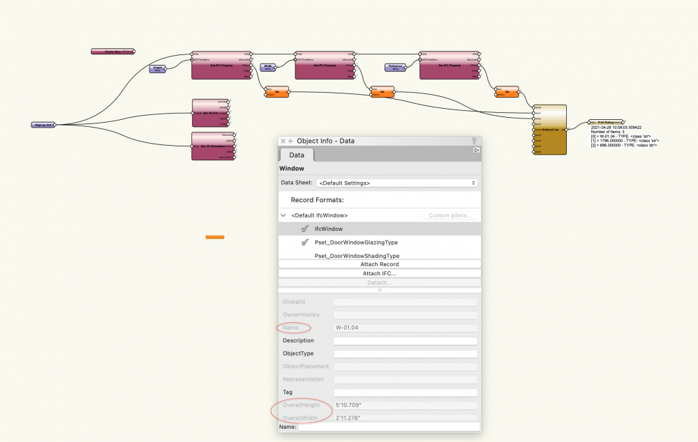
If you are using Vectorworks 2018, then I believe the menu command you are looking at is IFC Data Mapping. What you are seeing with "[Object.VW_Name] ELSE [Object.IDPrefix] + [Object.IDLabel] + [Object.IDSuffix] ELSE 'Window' " is the Field Value that is generated from pulling information from the Window object itself. With the Get IFC Property Node, you need to input the Field Name in order to get the Field Value. I believe in your example, the Field Name is Reference or IFCReference or something along those lines. When you input that into the node, the output will be the string value for this formula: "[Object.VW_Name] ELSE [Object.IDPrefix] + [Object.IDLabel] + [Object.IDSuffix] ELSE 'Window' ", or whatever the Field Value may be for the particular object you are querying.
-
Version 1.0.0
125 downloads
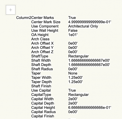
This menu command can be used on a selected parametric -- or plug-in -- object. Most plug-in objects in Vectorworks have a parametric record and this command can be used to see what the field names and field values are for that particular object. The values in these fields generate the shape and attributes of the object. I use this menu command to find out what fields a particular object has, so I can use those fields to incorporate that object into my networks. -
Version 1.0.0
310 downloads
Here are files that I use to do Marionette training. I thought that it would make sense to add them to the forum because they are useful in their own right, even without me talking through them. The Marionette 101 and 102 files go step by step through building Marionette networks. In both files, you can cycle through the Saved Views to see each iteration of the network and what geometry it produces. When you create a Marionette network you don't necessarily place all the nodes linearly from left to right, you build it in chunks of functionality, and the nodes that make up those chunks don't always follow from left to right like words on a page. Everybody might build their networks a little differently, but in these two networks, I show how I would solve these particular problems. The first network is a series of cubes that grow in size and that series can grow and rotate. This network has also been converted to a Marionette object and contains sliders in the final version. The second network is a series of squares that have a spectrum of colors applied to them. Because several steps of this network do not generate geometry, Saved Views have been added showing Print Debug nodes that display the values of the network. -
Hello - unfortunately I used a version of the Collate node that was not the same as in the default library. That node needs different inputs. Below is the thread talking about this, and I have attached a corrected script. EXTRUDED TRIANGLES.vwx
-
Weather Analysis Tools
SBarrettWalker replied to SBarrettWalker's topic in Resource Share - Marionette
Unfortunately there is bug in 2021 that doesn't allow the geopy python library to be downloaded, making these not useable in Vectorworks 2021. -
Version 1.0.0
201 downloads
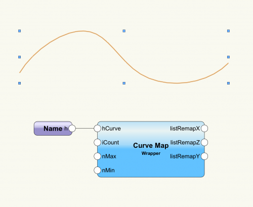
This is a wrapper that serves a similar function to Grasshopper's Graph Mapper component. To use the wrapper, connect it to a network, give it a minimum and maximum value for its domain range, the number of values you want in your list, and use a Name node to connect a drawn NURBS curve to the hCurve input. When you reshape the curve and run the network, the output list of values will change. You can use these values to shape, scale, array, or anything else in your network. Within the Curve Map Wrapper file is an example of a railing Marionette object and in the second file there is a vase Marionette object. Both use the Curve Map wrapper. This wrapper can be used in Marionette objects or regular Marionette networks.- 1 comment
-
- 10
-

-
Here are a few scripts that create random arrays of objects. They are probably not exactly what you are looking for but could be helpful.
-
One other thing - the Sequence node actually creates a list that is too long based on the number of vertices. The Series node works better. Fillet multiple polys v2021 SB.vwx
-
You were almost there. You got the list of vertices correct, but the hPoly input of the Change Vertex Type node needs to have the correct polys compared to the list of vertices. What I did was I "repeated" each of the poly handles so that the polys and vertices matched. I didn't duplicate them, I just repeated their handles in a list so the node would know to go back to that poly each time. This is one of those times when it is important that you have the same list lengths going into the inputs because if they are not the same length, the last item in the shorter list will simply be repeated over and over until the longer list is complete. Fillet multiple polys v2021 SB.vwx
-
I am not aware of any way to automatically ungroup geometry. FYI, the reason that Marionette scripts create groups is so that the geometry is "tied" to the script. The script not only creates a group, but names that group with a name related to the script, so that when the script runs again, the named group is deleted and replaced.
-
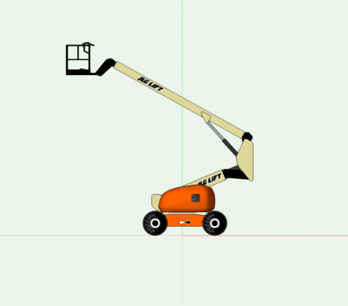
 The idea of this object is that it is a jumping off point. This was done in response to a user's request and covers the basic specs they were looking for. I am definitely open to improving the object but I also hope people will be inspired to update it themselves!
 -
 I see what you mean. I am seeing the same issue when I try to import it into a new file as well. I am filing a bug. -Sarah
 -
Does it only disappear after importing it into your drawing? Can you manipulate it in the original file? Can you tell if all of the "parts" import into your file as well? What happens if you click the Update button in the OIP?
-
I have added a 2021 version
-
 I have uploaded a new version that works in 2021
 -
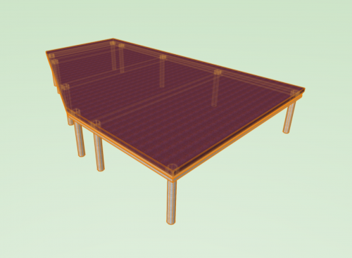
Version 1.0.0
294 downloads
This is a path-based Marionette object that creates a stage. This is a little different from the Create Stage... command as it allows you to make the stage from any shape and to choose symbol-based profiles for the frame, bracing and legs. It also uses a leg pocket symbol. You can edit the existing symbols to customize this stage or you can create your own library of symbols to use.