


SBarrettWalker
-
Posts
335 -
Joined
-
Last visited
Content Type
Profiles
Forums
Events
Articles
Marionette
Store
Posts posted by SBarrettWalker
-
-
When you use the "Sel=True" criteria in an Obj by Criteria node, the network will ONLY work once the network becomes a Menu Command. So when you are building that menu command, use a different criteria to test the rest of the network. When everything BUT the Obj by Criteria node is set how you want it, you change your criteria to be Sel=True, wrap it, and convert it to a menu command.
As far as your wrapper in that file, I believe it is because the name of the wrapper is only a number. If I delete the name it works fine. When naming your nodes, you can use numbers but only after letters. If you use numbers at the beginning of the names of your input nodes, the numbers will disappear when the network is wrapped and instead be used to order the inputs in the OIP.
-
 1
1
-
-
Unfortunately it's not that simple. The dropdown from the Solid Boolean node can't be exposed in the OIP of a Marionette object. In order to have the functionality exposed, you have to use a Valve node and place two Solid Boolean nodes in the drawing, where the Valve node would turn on and off the two Boolean nodes, depending on the True or False value you give the Valve node. The True or False value can be made accessible in the OIP. This would give you access to two of the Boolean functions. If you want access to all three Boolean functions, that makes it even more complex - I believe you could do it with multiple Valve nodes, but I would have to test it.
-
1
-
-
This is how default list handling happens in Marionette nodes. When a node receives input lists of multiple lengths, it repeats the last value of the shorter list until it has run through all the values of the longest list. You see this in nodes that are built to "expect" lists that are the same length, such as geometry creation nodes, like the Circle or Rectangle node. There are certain nodes that have special list handling, but it is usually mentioned in the description. In this instance of using the If node with multiple list lengths, you can use a Mix2 node before the If node, and you can decide with that node how you want the lists to be handled.
-
1
-
-
Hi @Nomi - The reason this is not working in your node is because vs.SetStoryElevation() takes mm as the input. You need to convert your document units to mm and then use that value as your elevation. I recently posted a network that creates a series of stories based on an overall building height. There is a Set Story Elevation node in that network that shows how to do this.
-
5 hours ago, jpccrodrigues said:
Just one situation to report: the precipitation chart doesn't work for my location. I attach the file so you can see if it is something from my location (absense of data?) or
Yes, unfortunately the precipitation data can be incorrect - these weather stations will often report precipitation as 0 when they should be reporting it as "missing" or "unavailable." It only seems to be true of the precipitation data. I haven't been able to figure out a solution.
-
1
-
-
17 minutes ago, line-weight said:
Regarding using a network without making it a menu command... whether it's in the form of a symbol or not, the idea is that you place it into the drawing space of whatever you're wanting to use it to work on, and then delete it from there once it's no longer needed?
Yes this is correct.
18 minutes ago, line-weight said:Once it's in the drawing space, what does and doesn't it act on - does it act on anything in that file, or just on that design layer?
It depends on the network/wrapper. Whatever the criteria of the network is, that is what it will act on. Most menu commands are created to work on selected objects, which is not possible with regular networks (because the network and the network alone must be selected in order to run), but if for example your network is set to look for every rectangle and change the attributes of them, it will do that, no matter what layer each rectangle is on. I have attached an example file doing this - each rectangle is on a different layer, and no matter whether the layers are visible or not, modifiable or not, the rectangles are changed by the script. If you want to specify layers or perhaps visibility, you can do that with the criteria node. To test this out, go to the criteria node in this script and add the criteria of visibility.
-
2
-
-
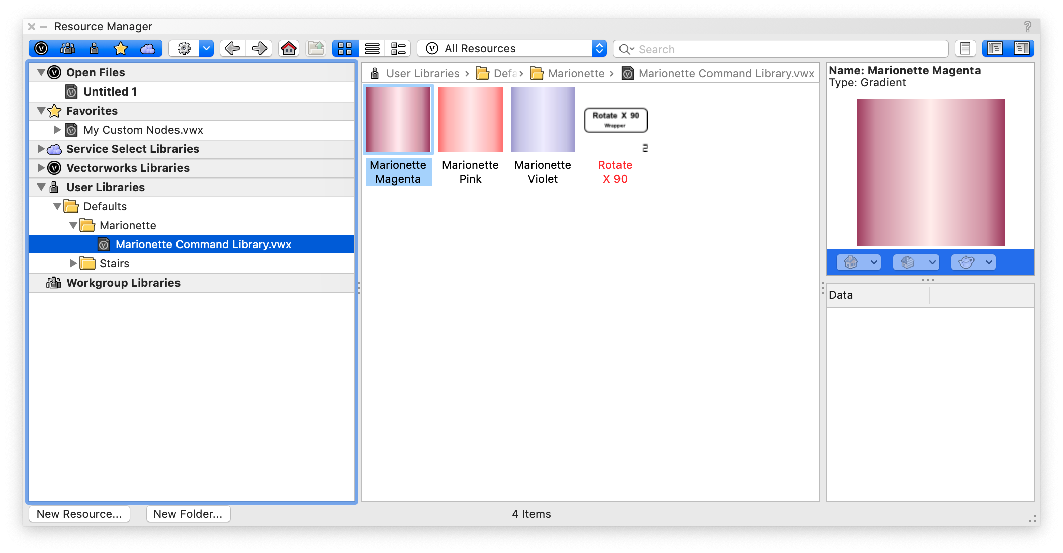
hello @line-weight - the Marionette menu commands that you create live in a file in your user library.
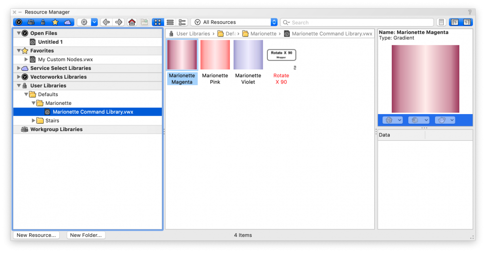
You can see in the image that I have a single menu command: Rotate X 90. If I wish to remove that menu command, I can open that file, go to the resource manager and delete that wrapper. If I wish to edit a menu command, its a little trickier. I can open that file, place the wrapper in the drawing space, edit the wrapper then RESAVE it as a menu command. If you give it the same name as the old menu command, the new one will replace the old.
If you wish to save a network to use in multiple files but NOT turn it into a menu command, you can simply wrap that network and save that wrapper as a symbol. If you have "Convert to Plug-In Object" checked when you convert it into a symbol, it will be a wrapper when you place it in a new drawing. You can transfer it to other files just like you would transfer a symbol. You can also see in the image of my Resource Manager that I have a favorite file called My Custom Nodes. That is where I keep custom Marionette nodes as well as wrappers in the form of networks that I may wish to use in multiple files. It's easy for me to import from that Favorites file into any open file.
I hope that helps.
-
I realized what was wrong. In your original script in the 2019 version, you had the prime value input into the Line node, instead of converting it to a point first. For some weird reason, this worked in 2019. I have updated the script so it works in 2019 and 2020. The other exciting thing is that in 2020 there is a big improvement in graphics performance.
-
3
-
-
Also, this network is super fun to play with! Just to try it, I converted your Integer Swirl to a Marionette object with sliders and also added the ability to fill the objects with a range of colors.
-
2
-
-
Is there a reason why you can't substitute the Count, Add List, and Int nodes for a Get List Length node because essentially isn't that what you are doing? Do values in the prime series repeat?
-
Perhaps you could try using the group node to group all of your points before changing their layer? In general however, I would recommend simply running the network with the layer that you want the objects to end up on as the active layer.
I also assume that it is the act of setting the layer that eats up the most time and not setting the class. Have you experimented with only changing the class?
-
Hello All,
Sorry I was late to respond to this, but there was a bug in the 2019 version of the node and I used a custom version of the Collate node. Besides the output not being lists of lists, the biggest difference between these two versions was that my custom node was looking for the number of items in each list while the default library node is looking for the number of lists. Here is a file with a slightly adjusted network that uses the fixed default Collate node in 2020. I exported it back to 2019 so that you can use this correct node in version 2019.
Example 1 - Extruded Curves v2020.vwx
Example 1 - Extruded Curves v2020 v2019.vwx
-
1
-
 1
1
-
-
You are on the right track and very close.
If you want the output value to be a symbol name, it needs to be a string. In order to create a string in your script, you must use quotation marks. Assuming that HR4 is the symbol name, you simply have to put quotation marks around it to make it a string.
if input == 0:
self.Params.output.value = 'HR4'
if input == 1:
self.Params.output.value = 'HR5'
if input == 2:
self.Params.output.value = 'K4'
if input == 3:
self.Params.output.value = 'K5' -
Unfortunately, the Get Z at XY probably won't work because a NURBS curve likely doesn't have an actual thickness. I created a work around that might work - I created a loft based on the curve, used the Get Z at XY node and then deleted the loft.
-
If your NURBS surfaces always follow the same curvature and change only in the length that they lay on the floor, you can create a bunch of surfaces that are the same size, then use the Extend NURBS node to extend each in a random manner. The Extend NURBS node only takes a single length value as the extension, so inputting a random list of lengths to extend a list of surfaces should work.
-
Here is an option for the issue of the bounding box. I found points along the edges of the surface and created a 2D poly from those points.
-
1
-
-
@Ash I have updated the Temperature Chart and it is located here:
The other charts I haven't updated yet.
-
2
-
-
@jeff prince I periodically update these graphs and post them in the Marionette objects section of the Marionette forum. You can check there to see if there are newer versions than the ones you have. I updated the Wind Rose pretty recently.
-
3
-
-
@VvierA Can you send us the file?
-
Hi @cberg-
Oh, the Space tool. There is a way to do this but its hidden. The parameters of each finish "key" are there in the space but they don't show up in the dropdown menu of the space's object parameters. I am not sure why this is true. I have built a data tag that is set up like the image you provided. I don't believe there is a separate trim finish in the space, only a base finish, so that parameter isn't included, but all the others are.
Let me know how this works!
-
1
-
-
From a scripting standpoint, I think you could easily put these objects in separate classes. Putting them in separate layers can be a little trickier, because the created geometry is always placed in a group and that group will be placed on the active layer, no matter what layer the objects INSIDE the group are on. The way around this would be to place your starting objects on the layers that you want them on, and then run your script with the active layer set to the layer that you want those objects placed on.
You can do this within the script with classes using the Set Class node from the attributes folder, or with layers using the Set Layer node from the Layers folder.
-
I noticed that your rectangle nodes are named and when I remove the Int node then those names appear on the outside of the wrapper. To keep this from happening, you can attach a 2D Vector node with the values of 1 for X and 0 for Y to the vRot inputs of the rectangles. Those are the default values for no rotation.
-
Hi @Palle-
It looks like you have an integer node attached to the "vRot" input of the rectangle nodes in one of your wrappers. This input requires a vector - that is what the "v" means. It looks like all of the Int nodes you are using have a value of 0 so you are not looking to rotate any of the rectangles. If you simply remove these Int nodes and leave those rectangle inputs open the script will work how you want.
-
You can think of this node as an alternative to the Bool input node. The output of the Yes No Dialog is labeled "b" meaning it is a boolean or true/false value. Yes would be true and no would be false. You can connect it to any node that has a "b" input and some sort of either/or choice. When you run the network, a yes/no dialog will pop up and you can choose Yes or No.
Marionette Object > Symbol
in Marionette
Posted
I am not sure what is going wrong here based on the image. Can you send the file?