
SBarrettWalker
-
Posts
335 -
Joined
-
Last visited
Content Type
Profiles
Forums
Events
Articles
Marionette
Store
Everything posted by SBarrettWalker
-
Version 2.0.0
460 downloads
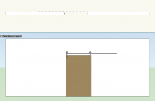
Here is a Marionette object that functions as a schematic Barn Door. It opens and closes with a slider and has separate 2D and 3D geometry. The wheel and hanger are a symbol, so if you wish to change their look you can edit the current symbol or create a new one. The insertion point of the symbol must be where the wheel touches the track. -
There is a way you can create this. You can use a Popup node in the Input folder. You have to edit the script inside by deleting the top line of the script and then adding the choices into the appropriate part of the script. The output of this node is the index value of the selection you make from the popup list. for example, if you have four choices: ['Red', 'Orange', 'Yellow', 'Green'] the corresponding index values will be [0, 1, 2, 3]. You can build a corresponding list of values and use a Get Item node to draw the correct value from the list. Popup.vwx
-
Here are a few scripts that work by placing 3D symbols at specific locations.
-
I believe that the output of the Get Cell Value node is already a string, so the Get String node is unnecessary. If you connect the "formula" output to the "s" input of the Text node it should work.
-
When a Marionette node creates geometry it is always placed in a group. The group is named based on the name of the node that created it as well as a random number - this ensures that when you run the script again, the object will be deleted and recreated, because that named group will be replaced. To edit any geometry created by marionette nodes, you will have to ungroup it first, no matter whether you use the group or ungroup nodes.
-

Error running Precipitation example using Geopy
SBarrettWalker replied to David O's topic in Marionette
Thanks for catching that - it was an error in the script. I have fixed it and uploaded a new version - this version is also in Vectorworks 2018. -
This may not be the most elegant solution, but I would rotate the poly to be orthogonal, create the grid, then rotate it back. Here is an example. Forum question.vwx
-
Ramp network from VSS forum Germany unsuccessfull
SBarrettWalker replied to Bernd Lützelberger's topic in Marionette
@Alan Woodwell This paper is on the Vectorworks website here: http://www.vectorworks.net/training/2018/getting-started-guides/transitioning-to-vectorworks/moving-from-grasshopper -
Ramp network from VSS forum Germany unsuccessfull
SBarrettWalker replied to Bernd Lützelberger's topic in Marionette
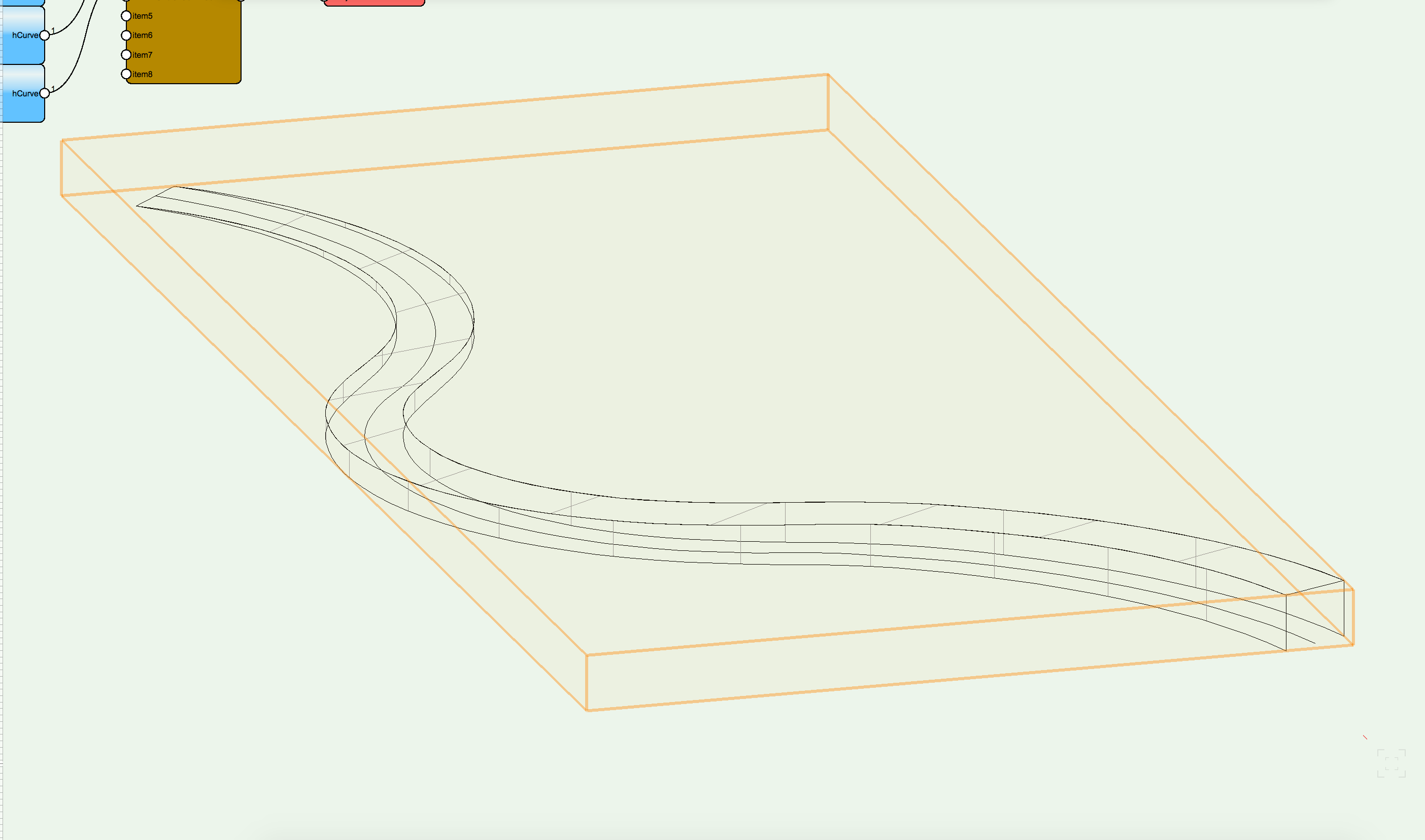
Ah, for that issue, you simply need to check "rule" in the Loft Surface node. That will give you sharp edges.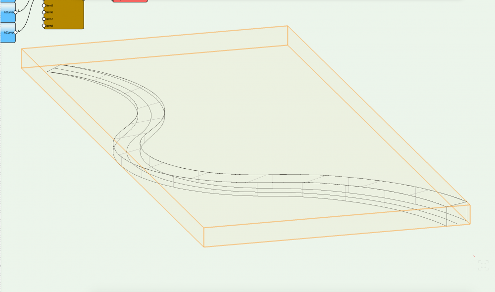
-
Ramp network from VSS forum Germany unsuccessfull
SBarrettWalker replied to Bernd Lützelberger's topic in Marionette
Hello @Bernd Lützelberger, I noticed in all of your scripts that the Int node is somehow connected to the first Range node twice, which is causing you to get 42 values instead of 21 values - if you try disconnecting it and reconnecting it should work. just make sure that when you run in debug mode, there are 21 values coming from the Range node. -
-
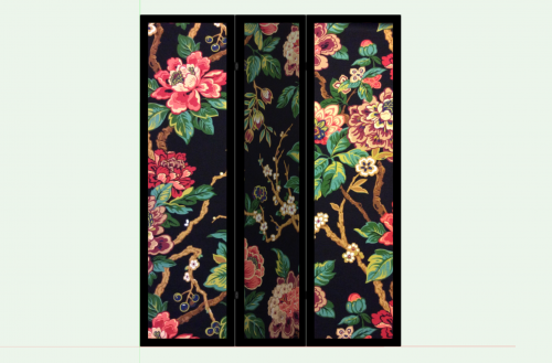
Version 1.0.0
83 downloads
Here is another Marionette Object with articulation. It is a simple room screen that has three panels with two hinge points. Each panel can be given an angle of anything between 0 and 90. -
getting an object-handle by mouse click on any object?
SBarrettWalker replied to relume's topic in Marionette
The only way to do this is to create a menu command. To create this kind of network, you will need an Object by Criteria node as the node that connects the object to the network. In the text field in that node you type "SEL=TRUE" and then convert the network to a menu command. The menu command will exist in Tools > Marionette Commands > [New Command]. To use it, select an object and then run the menu command. However, this may not be exactly the type of network that you are looking for. If you want to create a Marionette object with control geometry you can use a Control Geometry node instead, and then convert the network to a Marionette object. If you just want a network that references existing geometry (not as an MO or MC) then you must use a Name node. You have to give the geometry a name in the OIP, and then put that name in the text field of the Name node. -
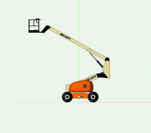
@Kevin McAllisterI have created a much simpler Marionette object that is built with articulating symbols that you can check out. It is built using the same principle as the Condor - each symbol is placed and rotated relative to the location of the other parts and the values in the OIP. It is located here:
-
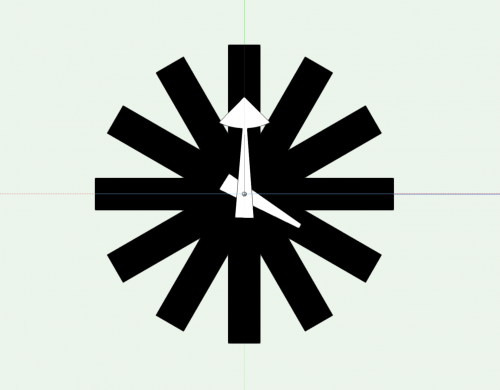
Version 1.0.0
37 downloads
This is a Marionette object that is a wall clock. The time of the clock can be set by sliders in the OIP. The three pieces of the clock: the face, the hour hand, and the minute hand are all symbols that can be changed. The only important aspect of the symbols is that the XZ value of the insertion point for all the symbols be at the center of rotation and the Y value be relative to the clock face. -
You can reference it just like any other symbol, just know that all of the parts will come with it, including the part symbols, the textures, and the Marionette gradients, but they will no longer be in folders, so it might be a little messy. The only thing you would need to do is to move the Condor60 PIO red symbol outside of its folder (that is the Marionette object). Then you can reference it.
-
Hello@digitalcarbon, A Marionette object functions just like any other parametric object - you can convert it to a symbol but you would lose the ability to edit it in the OIP. Just like a plug-in object though, it still has an insertion point. If you want to add geometry to make that visible you can by editing the Condor_base symbol (just don't delete anything from it or change its insertion point or the insertion point of any of the other part symbols).
-
I believe this will always happen because of the nature of Marionette objects. In this way they are also similar to hybrid symbols - the 2D geometry get treated differently than the 3D geometry. If it becomes problematic for the script, you can use the Set PRefID To Ground node in the Object Info folder to set the object to the layer plane while your script is acting on it. However I do not know if the object will stay on the layer plane if you ungroup the Marionette network from the control geometry.
-
It can be difficult to use multiple control geometries - the best way I have found is to group them all together and make the group your control geometry. Then you can use a Contents node to access them. Once you have the list of control geometries from the Contents node, you can filter them by name or type, etc.
-
Hello DE, Whenever you convert control geometry and a network to a Marionette object, the geometry will most likely move. What is happening is the geometry is centered over the wrapper, and that becomes the insertion point/center of the Marionette object. You can think of a Marionette object as a symbol or plug-in object - it lives as a resource to be placed in the drawing - it doesn't remember its original location. Having multiple pieces of control geometry can also be tricky. Are the separate pieces of control geometry keeping the correct spatial relationship between each other?
-
Custom Dialog Box In Marionette Menu Script
SBarrettWalker replied to Martin Crawford's topic in Marionette
Here is an updated file that does the same thing but without a custom node. It also does a third pattern. ArrayingSymbols.vwx -
Custom Dialog Box In Marionette Menu Script
SBarrettWalker replied to Martin Crawford's topic in Marionette
Hello Martin, Here is a script that places a symbol in an array based on a given number of columns and rows, and then sorts them and draws a line through their center points. There is one custom node, Reverse Lists Chunks, that allows you to reverse the order of lists within a larger list. I used this to create the line that swerves back and forth. ArrayingSymbols.vwx -
Hi Martin, I looked at your file, and it is actually a weird glitch that I have seen happen once or twice. Somehow, your H pass node is connected to the sequence node twice. This shouldn't be possible - it is definitely a bug, but if you disconnect the H pass node completely and reconnect it, it should work properly. HTH, Sarah
-
Marionette Script deletes class "0" in custom file template
SBarrettWalker replied to 112090006's topic in Marionette
I can tell you that when building templates, we STRONGLY recommend to leave the None class as None. There are a lot of different instances where the None class will be recreated even if you change its name, apart from scripts specifically. If it is important for your office to change the None class to 0, you can do this by mapping your classes to the AIA/NCS standard. Go to File > Document Settings > Standard Naming and choose AIA/NCS. This will set your None class to 0 and set your Dimension class to A-ANNO-DIMS. If you don't check "Enable Auto-classing" you can still use all of your office standard classes. hope that helps, -Sarah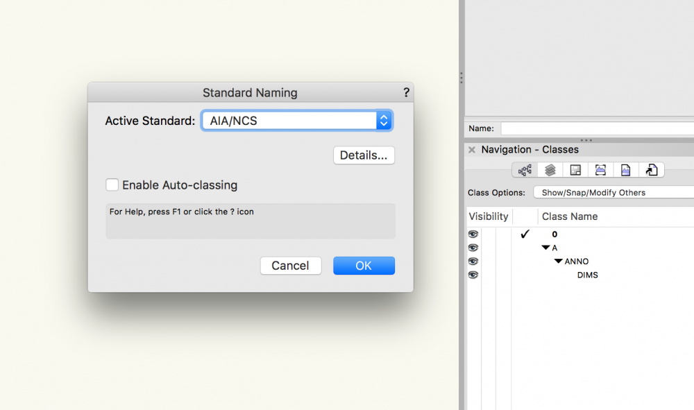
-
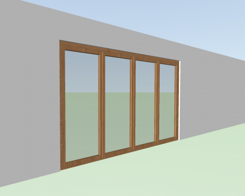
Version 2.0.0
573 downloads
This is a Marionette Object that can be used to simulate the WA67 Aluminum Clad Wood Folding NanaWall door. It allows you to set the panel width and height as well as the configuration and system. Based on these parameters, it calculates the overall frame width and height and creates a record format for the door that can be called in a worksheet. The insertion point of the door is the center left of the door, so if you choose a configuration with a different number of panels or you change the panel width, the PIO will extend or contract from the left (instead of from the center like regular door PIOs in Vectorworks). I would welcome feedback on the usefulness of this - is there something you would like it to do that it doesn't do? What does it do that you don't need it to do? As far as other types of NanaWalls (such as sliding panels), I am trying to figure out a way to script those as well.