

ericjhberg
-
Posts
581 -
Joined
-
Last visited
Content Type
Profiles
Forums
Events
Articles
Marionette
Store
Everything posted by ericjhberg
-

GIS - Export to Shapefile and Meeting Standards?
ericjhberg replied to ericjhberg's topic in General Discussion
It looks like my colleague already asked this question, so if anyone has any further input, check here first. -
We are trying to propose on a project that requires a fairly regulated interchange with certain GIS shapefile standards. I was wondering if anyone has had any experience exporting shapefiles (.shp) and if so, have you ever had to meet any standards? The requirements of our interchange are as follows: DIGITAL SUBMISSION STANDARDS: §The required format for digital submissions of the graphic data is an ESRI v10.4.1 shapefile or Geodatabase (personal or file) §Must be projected in NAD 83 CA State Plane V §Must contain FDGC and City compliant metadata (See section 08 for Metadata template) §Documentation on any MXDs or Domains created§Should be topologically correct against City data §Provide validation documentation (topologies, data quality checks)
-
Construction details - Drawing and reuse
ericjhberg replied to Christian Fekete's topic in Workflows
Once you make changes to a detail symbol (from either the original/mother location or in the referenced/child location) you should update the file reference exactly the same way you would update a Viewport/Xref style reference...from the referenced file tab. Out of date file references will appear in Red. -
Construction details - Drawing and reuse
ericjhberg replied to Christian Fekete's topic in Workflows
No, the L-Details file is our production set or sheet set file. It contains several different design layers at the various different layer scales used to create the details (again, each detail symbol is housed in its own separate file). We then reference the detail symbols into the L-Details file and place them on the appropriate design layer matching the scale of the detail. From there you can create individual viewports to take your details to the correct sheet layer. We often have 10 or more detail sheets, each displaying details at a variety of scales but generally organized by type. Each viewport (between 6 to 9 per sheet) could be at a different scale. Note: There is a difference between a reference viewport (xref for AutoCAD comparison) and a reference symbol. Really any Resource (symbol, hatch, linetype, gradient, record format, etc.) can be referenced from one file to another. In the details case this actually allows our office, since each individual detail has its own file, to work on each detail independently from the file where details are being placed on sheets. Simply updating the reference to that file, updates the symbol to show any updates or changes. -
Construction details - Drawing and reuse
ericjhberg replied to Christian Fekete's topic in Workflows
Christian, I will say first that I feel your pain. Figuring out what to do with details was a large stumbling block for us too, and honestly still is a little...although not as bad. My recommendation is figuring out a workflow that works best for you and accomplishes as much of what you want as possible and then sticking to it...as much as possible. For us, this meant going with a 2D symbol methodology. Each detail is a 2d symbol containing the annotations, notes and linework...drawn at a specific layer scale. Each detail symbol sits within a unique vectorworks file in a standardized library location. When needed, that file is copied into a project file and the 2d symbol is referenced (referenced symbol methodology) into the L-Details file with all the other details, but placed on a specific layer with a layer scale matching that of the detail. This way the standardized location stays constant allows for project specific updates of details, per project without altering the standard detail. We actually use very "dumb" text annotations (no callouts, general notes, or keynote legends) and page-based 2d symbols where necessary. That is because the database management becomes quite cumbersome when combining different details. We have started experimenting with 3D details and feel that this is where the largest strides can be made for us and Vectorworks going forward, but I honestly wouldn't prescribe our current methodology yet. Hope this helps. -
Railing Fence Tool - Corner Posts
ericjhberg replied to ericjhberg's question in Wishlist - Feature and Content Requests
Well that's a bummer. -
Railing Fence Tool - Corner Posts
ericjhberg posted a question in Wishlist - Feature and Content Requests
I really like the new railing/fence tool. It is a dramatic improvement over the previous tool. With that said, one thing that could use fixing is the handling of corner posts. If you are using a square post, the tool automatically rotates the corner posts to mediate the angle of the corner, rather than realistically squaring up with either the entering line or the exiting line. This is not a realistic application. For example a fence/railing with square posts that jogs frequently at 90 degrees. The corner posts are all at 45 degrees to the entering/exiting lengths of fence. Another improvement to this tool would be the option to offset the posts from the panels. Often fences have posts on the inside or outside of panels and not directly centered in the line of the fence. The posts should serve as the center of the fence line, but the paneling should be able to be offset to one side or another. In this case, this should also better support the ability to create top, middle, and bottom rails to support an offset fence panel. Think basic vertical picket solid wood fence. -
I agree that there needs to be some sort of better integration between sheet layers annotations and crops and design layer visibilities. I posted on something like this awhile back to no effect. What I imagine is a way to interact or at least visualize sheet layer annotations and/or crops from design layers. This would help in the placement of certain annotation objects that for whatever reason, cannot be located on a sheet layer (i.e. stake objects, irrigation ID tags, etc.) usually because they have to interact with other elements on the design layer(s). Placing these objects without reference to other annotations or view ports becomes an exercise in futility as you go back an forth, tweaking it to get it just right...annoying.
-
My wish: VW2021 to have no new features. Please.
ericjhberg replied to line-weight's question in Wishlist - Feature and Content Requests
I am in full agreement of the intent behind this post and hope that all of this massive FORUM index serves as the basis for existing tools to get improved. The frustrating part is that posting specific requests seems to fall on deaf ears depending on when and where items are posted. I have made several posts that have gotten 0 views or minimal response, while others seem to get tons, regardless of subject matter. As for improving existing tools, I agree that this should be a priority over the development of new tools. For example...text...maybe the most basic feature in the program. I feel like text handling alone is example enough of the frustrations with existing tools. No auto numbering, no auto bulletting, no support of multiple columns, no auto-indent. That is just the start. It seems as if a developer somewhere figured out how to code a text box and then said, done, on to how to draw a line. I also agree with vetting tools before release. On this point, the irrigation tools. I was thrilled to learn about their release, but after using for one day, realized that I cannot practically make things work to develop a real irrigation plan, simply because you cannot graphically rotate components, tags, etc. To the point mentioned above, I have made several posts about these issues with almost 0 response, mainly because I don't know how interested the community is in irrigation. Hope to see actual improvements in how development works with the reality of project development and documentation. -
Also, is there a 3D symbol node that accounts for Z values in placement? The basic library version only factors 2D points.
-
Thanks so much Alan, I was able to make it work as far as duplicating along the path and use a math turn around to divide the path evenly per a defined spacing. The next problem is orientation. The duplicate along path command allows you to 1) center objects on path, 2) keep them tangent to path and retain the original orientation. How would I go above setting rotation angles tangent to the created points along a NURBS curve in this example?
-
I'm trying to figure out how to duplicate on object (symbol) along a 3D polygon with a marionette node. The command Edit>Duplicate Along Path works great but not in a custom marionette script. Any ideas?
-
Realistic Road/Grading Tools ??
ericjhberg replied to nca777's question in Wishlist - Feature and Content Requests
100% agree. We have found some creative uses for the NURBS Road tool to essentially create complex vertical curve profiles for roads, sidewalks, swales and really anything curving both horizontally and also vertically. As brought up though, this is not done with the horizontal accuracy needed. NURBS as objects don't seem to have the inherent properties necessary to define precise curve and tangent layouts for roads. -
Viewport Visibility - Save Settings
ericjhberg posted a question in Wishlist - Feature and Content Requests
Along the lines of document management requests. I have another idea for streamlining viewport visibilities within a document. Could there be a way to Save the visibility settings associated with specific viewports. Those settings could be stored in a dropdown that could be accessed in each of a documents many viewports. This would create one location to manage different visibility settings. Furthermore, if changes were needed to a specific setting, they could be made in one location to affect all of the viewports using that particular setting, eliminating the need to Match properties or use more cumbersome control methods for managing multiple viewports' visabilities. I'm imagining something similar to Saved Views, but specific to viewport visabilities. This has probably been brought up elsewhere, but I thought I would reiterate. -
Collapsible sheetlayers
ericjhberg replied to Itchy's question in Wishlist - Feature and Content Requests
This has been brought up several times and is becoming increasingly important as our design files increase in complexity. Also, the entire concept of Project Sharing relies on the use of ONE file, but if that ONE file has too many Design Layers and Sheet Layers, it is unmanageable. I'm hoping an update comes soon? -
When building complex, multiple viewport drawing sets, we encounter the difficulty of having no Design Layer reference for Sheet Layer viewports. I'm imagining a solution where Viewport Crop objects could appear in a unique design layer and be linked. In this fashion, the crop objects could be manipulated in this design layer and the changes would be reflected in the Sheet Layer viewport. Perhaps these crop objects become plug-ins "Viewport Crop" to maintain the link and control the parameters in both locations. There would have to be some account for the ability to rotate viewports once on a Sheet Layer though. Along the same lines, what if viewport annotations could also be represented in a unique design layer? I know the impetus of separating annotations from Design Layer was to keep page based information separate from design information, and perhaps this suggestion goes a little backwards in that manner. We run into the circumstance often where objects that we would like to only appear in Sheet Layer annotations HAVE to be placed in design layers instead. This is true for any of the new TAG elements associated with the irrigation tools, or tag objects in general. We have to place these in a design layer, but have the ability to visualize them on a sheet. Add in the difficulties associated with rotated sheet layer viewports and keeping annotations positioned correctly becomes increasingly difficult, especially in complex, multiple sheet documents. As a whole, I think document management is one area where Vectorworks can make tremendous strides in user efficiency, and this is just one suggestion to help in that manner. Other threads in this vein are:
-
Tag/Callout Based on Record Field (Label GIS)
ericjhberg replied to ericjhberg's question in Wishlist - Feature and Content Requests
I'm piggybacking on my own request here...just stumbled back on it. This is a potential huge timesaver for all kinds of different workflows. It also should have the ability to work in a viewport's annotations. -
Choppy Contours II
ericjhberg replied to nca777's question in Wishlist - Feature and Content Requests
+++1 -
Custom Title Block - Multi-Line Text Fields Don't Automatically Wrap
ericjhberg replied to rDesign's question in Known Issues
Yes...all the time. I just try to edit the multi-line sheet title in the sheet border dialogue box and it crashes almost every time...very frustrating! -
Unfortunately, no...the worksheet image function responds to the documents current class visibilities when the worksheet is recalculated. If you set your visibilities to the view you want your worksheet to represent and then recalculate the worksheet, you should see the images respond accordingly. The entire =IMAGE function is a wishlist item that is in desperate need of repair. Sorry this probably isn't what you were hoping.
-
Easily Remove Criteria from Database Header
ericjhberg replied to ericjhberg's question in Wishlist - Feature and Content Requests
Good workaround, thanks Michael! Even though I kinda hate workarounds, this actually seems like the best way to clean up the criteria with the current functionality. -
We have been experience similar difficulties and crashes with callouts lately. Fixes immanent?
-
Easily Remove Criteria from Database Header
ericjhberg posted a question in Wishlist - Feature and Content Requests
It would be nice to have the option to delete a particular criteria choice within a database header rather than just using the "Fewer Choices" to eliminate just the last (bottom) criteria choice. The current methodology for eliminating criteria at the top of the list is cumbersome if you want a clean list of criteria, free from "All Object" choices. I've had criteria that are more than 10 lines long and eliminating the first, third, and seventh lines is impossible without assigning a "All Objects" choice to it. I see two options for fixing this. 1. Consider an interface with + and - buttons for each line instead of the "More Choices" and "Fewer Choices" buttons. 2. The second option would be, when changing a criteria to "All Objects", the list reorganizes to put those choices at the bottom of the list. The user could then use the "Fewer Choices" button to remove the unwanted lines.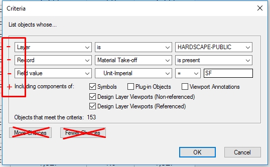
-
VW2017 Irrigation Crashes...repeatedly
ericjhberg replied to ericjhberg's question in Troubleshooting
Lance, I have sent a file to Vectorworks Tech in attempts of trying to resolve the issue already. Unfortunately we aren't talking a LITTLE, easily sent file, as the one I am working in right now is over 1 GB in size! It is getting ridiculous. I can't even add a component to an mainline without a crash and I have a file with over 40 mainline modifications to make! As for the reculculations, Vlado did suggest this fix to me earlier and it DID NOT solve the auto update issue. After modifying the .xml as directed, the program still took several seconds (sometimes more than 10) after each move. It is as if it was still going through the motions, but perhaps the data wasn't flowing the same way??? My wishlist is that the autocalculate can be turned off within Vectorworks running application allowing me to design irrigation freely without delay, then I can manually perform recalculations when ready. I don't want to modify an .xml file because that is troublesome in a workgroup situaton. I am at a loss right now with the irrigation tools. They are too cumbersome in the current array, with too many flaws, to implement efficiently or properly. I would love to be able to provide better feedback to help solve some of the problems we are encountering, but large file sizes make sharing difficult and we are very busy with our day-to-day. If there is something I can help or input I can provide, please let me know. -
One of my longest standing wishlist items that I am only now posting to the forum has to deal with snapping tangents from an object to a curved/arced object. Be it a circle, arc, arc-polyline, the tangent snap point does not work when drawing an arc or polyline to that feature. To better illustrate the problem I put together a short screenshot video. I have also linked another thread because of it's relevance to the situation
