jeandm
-
Posts
40 -
Joined
-
Last visited
Content Type
Profiles
Forums
Events
Articles
Marionette
Store
Everything posted by jeandm
-
Hi @LarryO Thank you very much for your response and being so thorough providing alternatives. I think I will create a hybrid symbol so I can control graphics a bit better. I won't need to take quantities of get a schedule from the drawings. Thanks again!
-
Hi, Just like Josh, I am looking to change the centre mark. Is there a way to achieve that, please? Thank you.
-
@Tom W. Yes, I have changed the stacking so far, that's how I got the screenshot I sent. I just cannot understand why the 2D fill is not a thing completely separate from the 3D texture. It seems like a missing piece. I would like it to happen in model space because this is where I do the drafting, so I would prefer to work on a platform that actually looks like what's going to be on the sheet. That's okay though, I will make it work this way. Thanks for all your help Tom. Have a good rest of your day 🙂
-
@Tom W. Hi Tom, Thank you for the response. Yes, I understand how to make it work on the sheet. Can I achieve the same result in model space? Thank you.
-
Hello, Thank you for your response. I mean that I want to see the walls solid in 3D (with its texture) and I want to be able to see objects through it in 2D. I attached a screen shot of what I want in 2D and 3D (note that when I see what I want in 2D, the wall is transparent in 3D. Thank you so much!
-
Hi All, I am trying to get a wall with multiple components to display a solid texture when looking at it in 3D but have the component display no fill in 2D. If setting the "Edit wall attributes..." Fill to None, then the wall appears transparent in 3D even though each of the components have a texture. Which must be normal, but then, how do you force the component (for which the class fill is already set to transparent) to show no fill in 2D? Thank you!
-
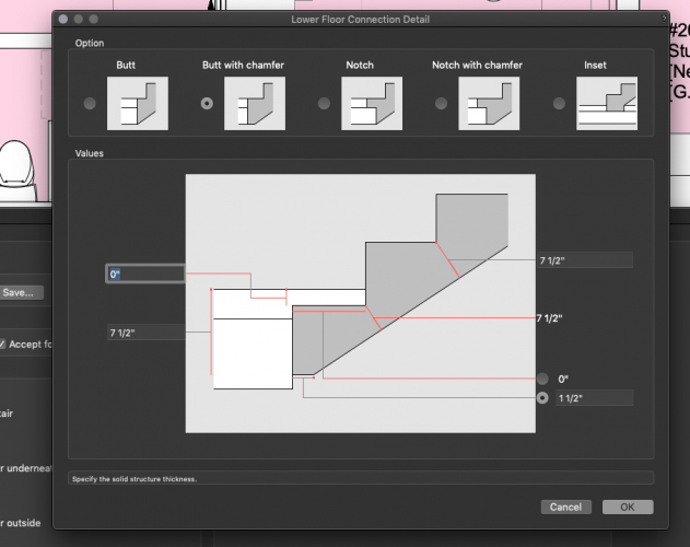
Never mind, I figured it out. 2021 comes with a bunch of new options for landing details (Stair to Slab connection) and I guess some of the old settings are not accepted anymore as some of the new options make more sense. See screenshot attached. I will leave this here in case someone runs into the same issue.
- 1 reply
-
- 1
-

-
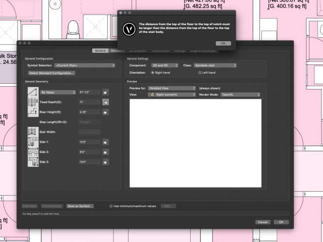
Hello, I was wondering if anyone has experienced this stair object error when converting an existing 2020 file to 2021: "The distance from the top of the floor to the top of the notch must be larger than the distance from the top of the floor to the top of the stair body" These stairs worked fine in 2020 apart from the usual 3D glitches when using the clip cube. But when converting the model I am getting this error (See screenshot). I can just rebuild the stairs but I would like to understand what's happening. Thank you!
-
adding editable cells to pre-formatted schedule?
jeandm replied to archdaly's topic in General Discussion
Thanks Pat, I thought from your other posts on the topic the Record.Field would be the way to go but I have not had the courage to dig into it yet. I think I should, it sounds promising. I will surely take you up on your offer for more help if needs be! Thanks a lot! Jean -
adding editable cells to pre-formatted schedule?
jeandm replied to archdaly's topic in General Discussion
Hi Pat, Thanks for the quick response. I understand for the greying, that's okay, it would make things a bit more legible. Regarding the recall on database cells, I was simply trying to retrieve all my door numbers into a manual entry worksheet. I used a workaround. I originally was trying to get some manual input into a database worksheet but understood it wasn't possible by reading some of your older posts. The goal was to create a decent graphic output for a hardware schedule. So I ended up creating another worksheet (manual this one) format it like the database door schedule and put them right next to each other (see screenshot) Thanks for your help!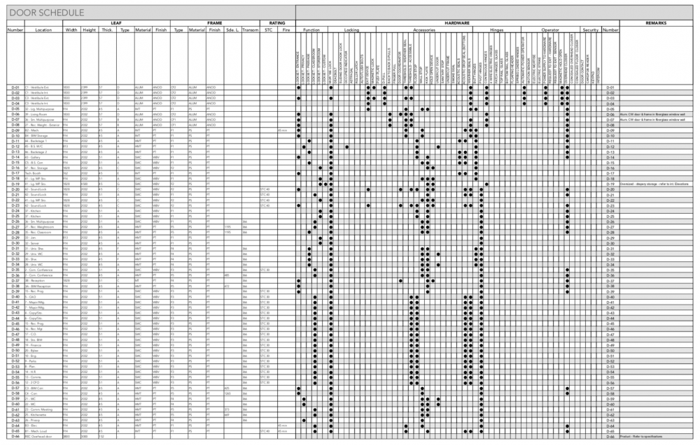
-
adding editable cells to pre-formatted schedule?
jeandm replied to archdaly's topic in General Discussion
Hi, On a similar topic, I am trying to format cells in a database. The database worksheet (door schedule) is quite long, and I would like to use a grey fill in every other row. But as soon as I format a cell, the entire column takes on the same attribute. Is there a way around that? Is it normal. Second question, can I retrieve cell results from a database worksheet into a regular (manual entry) worksheet. I can recall other worksheet but I cannot seem to find the proper way to recall the cell from a database as they are labelled in the format "A1.1" and the "." seems to throw off the formula. Thank you! -
Super! Thanks @michaelk that's a good tip to extract the 2D component of the hybrid symbol. I guess, I will turn it into an autohybrid to get it cut at the appropriate height. Thank!
-
@michaelk @Pat Stanford Thank you so much, I will test these options. I haven't used either the custom leaf or "use symbol geometry" for door in the past. I should have thought about Pat's option as I think I remember using that for windows. Anyways, thank you both very much for taking the time to reply and being so thorough! J
-
Hello, I was wondering if anyone would be familiar with a way to adequately model a folding overhead glazed door? I can certainly model a door and insert it as a symbol, but I want the door schedule to pick it up. I attached an image to give you an idea of what I am after. Thank you!

-
Convert a planar NURBS Surface to Polyline
jeandm replied to Stephan Moenninghoff's topic in Marionette
I see, I misinterpreted your intention! I'll do some more digging. -
Convert a planar NURBS Surface to Polyline
jeandm replied to Stephan Moenninghoff's topic in Marionette
Hey, It's dirty but it works if you input enough accuracy... For some reason it says that it returns as many POLYs as the number of vertices, but in the group there is only one... Go figure NURBS TO 2D POLY.vwx -
3D Door and Window Tags On Both Sides
jeandm replied to Tom Klaber's question in Wishlist - Feature and Content Requests
Any news on this? In fact, being able to manually control on which side (or both) the tag shows would be very useful. -
Thanks for you reply Cberg! This again seems like a big workaround for such a simple task. You can always insert multiple objects, but why cannot VW handle one single proper curtain wall? Finding workaround is not a problem but its clunky and cumbersome when it needs to be edited. Thanks J
-
Pat, Thanks for your answer! This is really too bad, it seems like such a simple thing. Thank you. Jean
-
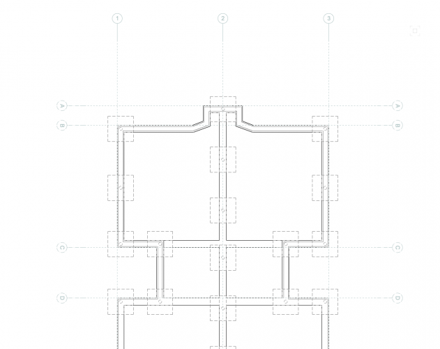
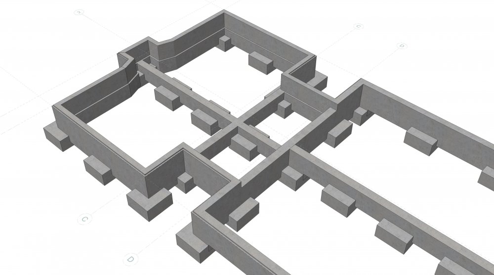
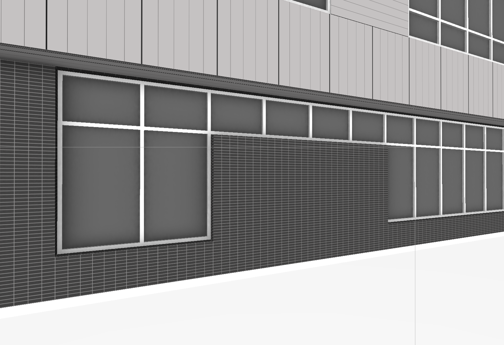
Hey Zoomer! You can integrate curtain walls in wall no problem if you convert the curtain wall into a symbol. The version that you see on this image is actually a symbol composed of multiple window objects which have their mullion overlapping each other. It could be done with multiple CW objects (as a single curtain wall does not allow stacked vertices, see above) but I find the window objects a lot more precise and reliable even though less easily editable. The symbol also has a 'hole component' which takes into account the difference between frame dimensions and rough opening. My reason for using a symbol rather than just windows is that I want the clerestory windows to show at dotted when in plan and full cut when showing the reflected ceiling plan. So with a hybrid symbol and a game of class visibility in the 2D definition of the Symbol, I can get the whole thing to display properly. But all this is just a workaround for something that Vectorworks should be able to do... The Curtain wall tool is very clunky and pretty slow and glitchy. It often crashes VW too. You can however locate the single elements very accurately if you set up your view as elevation with a rotated 3D view if necessary and define a local working plane. From there you can just work on screen plane pretty comfortably... but yes, all this for that, right.. Stepped window example.vwx
-
Hi Wes, Thank you for your reply. Yes, in this case that works as the door comes down. But if you try to have the brick come up in the opening instead of the door (see image), I cannot make it work as well unless I juxtapose multiple curtain wall objects side by side. As shown on the screenshot in the previous message, the handles are always off by one millimetre. Thank you.
-
Hi Alan, Thank you for your response. I did have an issue in the sequencing of the nodes. I recreated a CW the way you suggested but I still get a 1mm difference... Do you get the same thing? A subsidiary question would be: Is there a way to have the opening in the curtainwall larger at the top than at the bottom? Thank you so much for your help! Stepping CW.vwx

-
Hello, I addition to not being able to create a stepping curtain wall with vertical steps, I do not seem to be able to create a curtain wall object that is only represented with dashed lines in Plan view. There is always solid black lines that show under the dashed lines. Has anyone encountered this issue in the past? Would anyone know how to resolve the problem and get rid of those under-lines? Thank you. DASHED CW.vwx
-
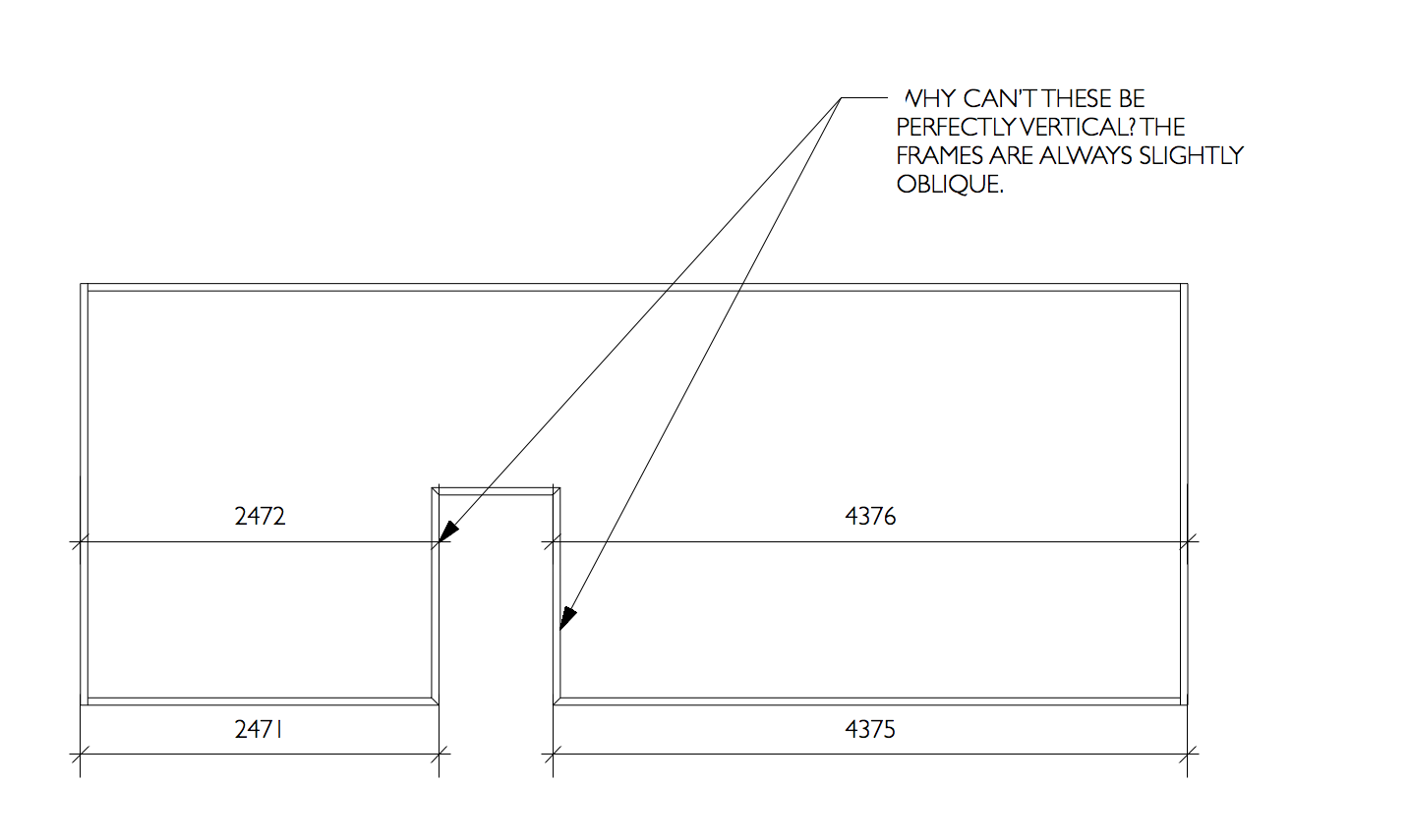
Hello, I don't seem to be able to create a stepping curtain wall. It appears that you cannot have vertical curtain wall edges other than the start and bottom frame. Anyone know how to do that without creating multiple curtain wall? I attached a file with the question pointing at the problem on sheet layer. Thank you. Stepping CW.vwx
-
Hello, I need to run a script on a large number of objects and think there must be a better way than duplicating the script for each object, hence my question: Is it possible to input multiple objects using the Name Input node? Thank you! J