


EAlexander
-
Posts
542 -
Joined
-
Last visited
Content Type
Profiles
Forums
Events
Articles
Marionette
Store
Everything posted by EAlexander
-
Well this is kinda great - but why so hidden? Add this button to Open GL options! Love the look!
-
I would draw that proscenium in front view with SCREEN PLANE active in 2D and then extrude it.....or draw it's footprint in top/plan view as 2D then extrude it. I would then draw another rectangle for the proscenium opening, extrude it tot he correct height and SOLID SUBTRACT it from the first extrude. Not that this is better, just offering a different perspective on how to approach this.
-
 Canvas doesn't look perfect, but the Surface pro is just way too underpowered for the price and 3d work: though I want one for photoshop and post production work.
 -
Honestly, not sure. I saw a lot of fuss over this when it launched, but as of yet, haven't seen on in the wild. Just remembered it as an alternative option that was cheaper, and not all in one with a low grade GPU.
-
Tom - why not look at a Cintique or this thing from Dell: http://www.dell.com/en-us/work/shop/cty/pdp/spd/dell-canvas-kv2718d/s001pdc27us And then attach it to whatever hardware you want. e.
-
I actually do it manually starting with just one seat (A hybrid symbol). I never use the seating tools - I haven't found them to be accurate or easy to work with and I like to keep it simple. I'll start at centerline, x number of feet back from the stage and build out my first run. I usually only put 14 seats per run to keep fire egress in check, and then add a row gap (4' or 6' depending on the job). I build out the whole first row this way and this gives me an idea on width and numbers per row. From there I group and duplicate array or use the move to points tool to create rows. Standard for me is to leave 2 feet from chair back to chair front. Some people try to do 18", but I prefer 24 for comfort if possible. I'll add left to right aisles (parallel to the stage apron an d 6 feet wide) at a logical break point. I try to build out the whole thing, only working on House left or house right. Once I'm satisfied, I mirror everything over centerline. I put all the rows and blocks into one master group - go into that group and ungroup all the rows. This way, I only have one group envelop and by hitting select all, I can get an accurate count from the OIP. Important to not duplicate or double up seats or rows as this will really throw your numbers off. Angled seating is more finicky, but I use the same basic method. I never put one chair alone, even if it fits - people like to sit together. For sweeping rows (curved). I make sure to have an accurate locus origin point for everything and tend to use the Rotate tool in ROTATE AND DUPLICATE mode. It takes a while to do this, but I start with one, then grab two and turn that into 4, then 4 into 8, etc. You have to do each row (different radius) manually, so it's slow going, but it works. I've tried Duplicate along path for this, but never satisfied with the results. I use a low poly 3D chair as part of the symbol. After I move the model into Cinema 4D, I usually swap out the master chair symbol for a higher poly one and then all the instances update. As long as things are tidy, centered, and the same size, you're good. All that said - massive seating layouts are one of my least favorite ways to spend an afternoon - but not as bad as actually setting up the chairs on site e.
-
Hi guys, I just wanted to say thank you to all who contributed to this thread. I've just used this technique for a big rotated truss structure for the first time and it works great. I used to make a copy and convert all the truss to groups and have special lighting symbols that weren't hybrids and it was a lot of extra work. This works really well. One note to future users - I am accustomed to making my viewports by drawing a rectangle over the objects and then using that as the crop. This can create problems in other viewports down the road. I was making a front elevation of the whole stage and half the truss structure was clipping due to limitations of the crop. So I remade the viewport, but just selection the truss structure and then Modify>Create viewport. Works perfect now. Thanks again. e.
-
Circular Truss Tool
EAlexander replied to Kevin McAllister's question in Wishlist - Feature and Content Requests
+1 -
Not to take away from the EAP discussion, but @cberg - in the example you give above, I would just draw the side profile of the object and extrude it. Always more ways to catch that fish
-
Circular Truss Tool
EAlexander replied to Kevin McAllister's question in Wishlist - Feature and Content Requests
Yes! I would add that it would be nice if the radial dimension (or diameter) reflected either the OD or the ID (ideally we could choose) instead of the middle of the truss. -
I think..... Try changing out of top/plan into a 3d view, like right isometric, and then try to export. Truss works like hybrids and will export its current visible state. Weird, right.
-
$5455.00 for Braceworks: https://secure.vectorworks.net/estore/braceworks Though it says to call for introductory pricing.
-
Excellent! Now if they could just make it so the Enter key drops focus on that entry field, I would stop importing objects named X on every show
-
Keep this in mind, Andrew: Naming your objects and groups in VW can really help set you up for success in Cinema. If you build out an elaborate model, but don't name anything, it will come into cinema as "Extrude, Solid Subtract, Extrude, Extrude, Null>Solid Subtraction" etc. While naming your objects or groups can add another step to your work in VW, it makes a huge difference in what you get in return in C4ds object manager. I find that I am now naming individual objects less and less, but putting things into groups with logical names. Groups come through as Nulls in Cinema. Null is just a fancy name for a group folder (parent) with the objects inside of it (children). You can, of course, use empty nulls for other things in Cinema (light targets, animation markers, etc) - but as far as organization goes - its just a folder structure. To name an object or group in Vw, select your object and switch the OIP over to the DATA tab. There is a field for name near the bottom. e.
-
https://greyscalegorilla.com/intro-to-cinema-4d/
-
Assuming this is all 3D - it sounds like the axis got rotated in translation from other software. You should grab the whole Stageline model and just rotate it to the correct orientation.
-
BTW - C4D R19 is ready to download - (finally Yippie !1eleven!!!)
EAlexander replied to zoomer's topic in Rendering
My take - and purely speculation - I think they realized it was important to catch up to the current GPU render engine offerings before they get any further behind the curve. They released it half baked to get it going quickly and refine it in future releases. With the core rewrite, the current rumor mill is that R20 is going to bring huge changes. We'll see. Pro Render is existing tech, so they could bolt it on and then fine tune the integration instead of building completely from scratch. I think a lot of people and studios are still using Physical renderer, but the visibility of Octane and Redshift can't be ignored for GPU power and quickness of workflow. Once you get a true IPR experience when creating lighting and materials, it is really hard to go back to the old ways. Then you have things like Corona and Arnold starting to really show what a CPU render engine can do (fast IPR, simple settings) and I think they wanted to try and keep up with this trend somewhat as well. If you look at the work being generated in Cinema, it feels like most of it is happening now via 3rd party - but I don't have actual numbers. Also - Pro Render is slated to work with AMD GPUs which Octane, Redshift, and other CUDA based engines can't do - so I think they are trying to get something to the Mac users and get their foot into that niche. Personally, I'm full in on Octane and Corona and for the first time in 12 years am back on a Windows machine with multiple GPUs and overclocked cores. I haven't done a job in Physical renderer at all in 2017. Pro render isn't really of interest to me, but I see why they are doing it. I don't always like how Maxon deals with things, but they are very smart and it is the most stable software I've ever used. -
copy and paste between drawings
EAlexander replied to MRD Mark Ridgewell's topic in General Discussion
I do it a million times a day. Make sure you are pasting into a layer with the same scale. Sometimes that can throw you off. -
BTW - C4D R19 is ready to download - (finally Yippie !1eleven!!!)
EAlexander replied to zoomer's topic in Rendering
Zoomer, make sure your glass panes don't have a phong tag. That can mess up flat glass at rendertime sometimes. -
BTW - C4D R19 is ready to download - (finally Yippie !1eleven!!!)
EAlexander replied to zoomer's topic in Rendering
If you want amazing render engine that works on the trash can Mac, look at Corona. It's free now while in development. Easy, cpu based, and gorgeous. Ipr is coming (already in the road map and working in Max). I played with prorender on Friday for a bit. Better then I expected, but can't hold a candle to Octane. -
Send to C4d wishes
EAlexander replied to grant_PD's question in Wishlist - Feature and Content Requests
1. Agree 1000%. This is really annoying and kills me with seating layouts and lighting fixtures. There is also something weird when distributing symbols with Move By Points tool - lots of times I won't get instances, but raw geometry for each symbol (LED Video wall tiles). 2. I hate this system so much it generally keeps me from using 2017 and sticking with 2016. It used to be that the master symbol was at the top of the null and the instances were grouped together with it. The hidden symbol folder with everything at 0,0,0 is just awful. There is no way to edit a symbol in relation to other geometry in the scene since they are all out of context. I make hybrid symbols of everything, so this overall workflow kills anything practical for me. Zoomer and I have talked about this before. He likes it - I hate it...a lot. 3. I don't do lights, cameras, or textures in VW - I do it all in Cinema, but I think this is a good request for those who do. -
I should mention that the DPI of the sheet layer will affect the "width" of the lines (higher the DPI, thinner the line). If you need thicker lines, try using an artistic renderworks option with a Pen setting that will let you control the pixel width.
-
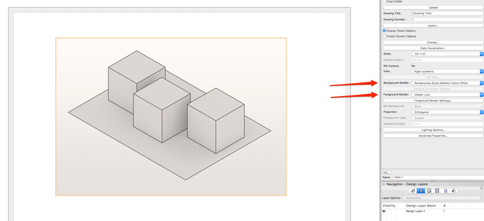
You can make a viewport of the view that you want on a sheet layer. In the Viewport settings via the OIP - set the Background render to the white model render mode that you want and then the Foreground render to Hidden line? See attached. Or am I not understanding what you want?
-
Hi - You can set the SCALE for each viewport independently - and independent from whatever scale your design layers are at. So you should set the size of your sheet layers (11x17 or 24x36, 8.1x11, etc) and then try the scale that fits best: Select the viewport, and in the Object Info Palette, there is a menu for scale. Different viewports in the same sheet layer can have different scales. So you can do a full scale detail next to a 1/4" ground plan, for example. Then you would add notes and dimensions by ANNOTATING the viewport. This way the text and dimensions are in the same scale as the viewport and make sense logically.
-
I still say Cinema 4D should be the model for how this functionality is implemented.
