
EAlexander
-
Posts
541 -
Joined
-
Last visited
Content Type
Profiles
Forums
Events
Articles
Marionette
Store
Everything posted by EAlexander
-
@Hugues Is this enough info? Attached.
-
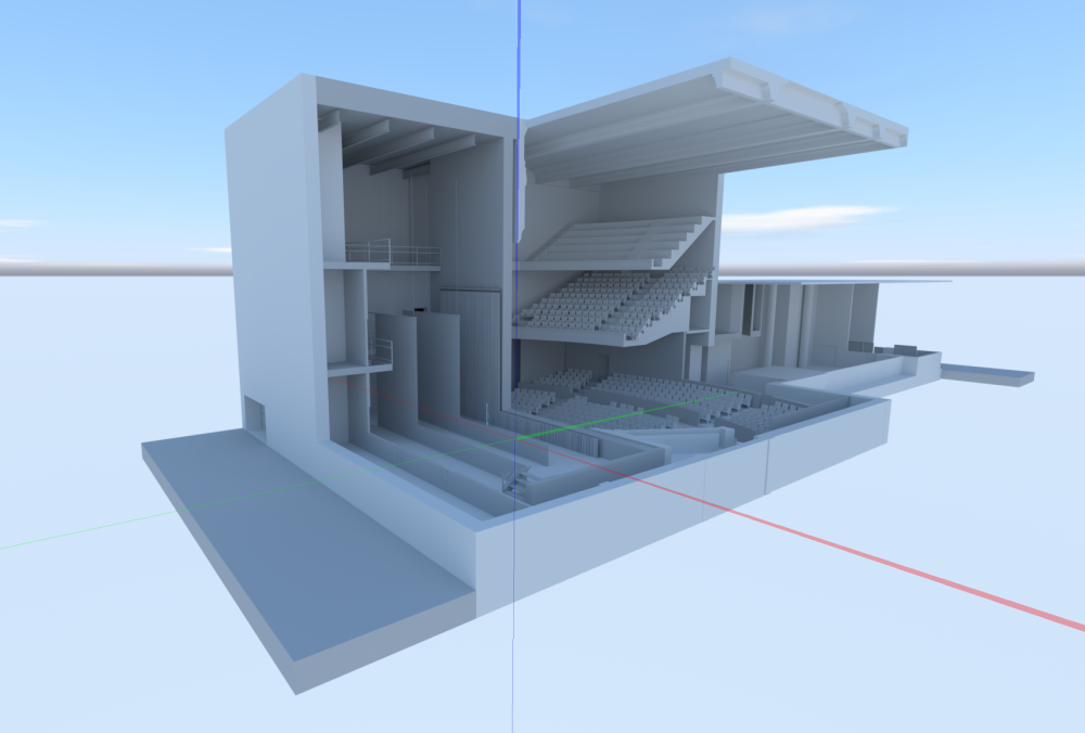
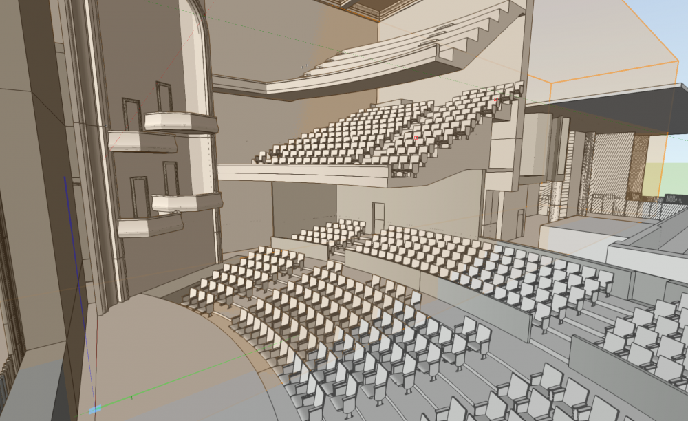
@HuguesThanks - here you go - attached. This is just solid modeling - no PIOs or anything but extruded geometry. Crashes 2022 before I even get it fully opened. Can't copy and paste it from 2020 to 2022 as 3d. EDIT: just noticed the file name has CORONA in it - this is referencing the render engine in Cinema 4d, not the virus 🙂 11_10_corona_buildv01.vwx.zip
-
Sadly, any file pre 2020 that I try to open gives instacrash. See y'all in a few service packs. EDIT: even weirder - I open a file in 2020. I copy all the Geo to the clipboard - move over to 2022 and paste.....I get a 2d line representation of my model (like I ran convert copy to lines and no 3d. ☠️
-
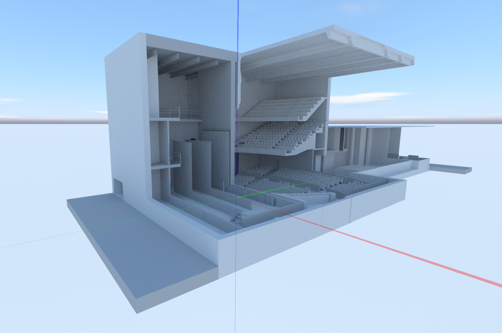
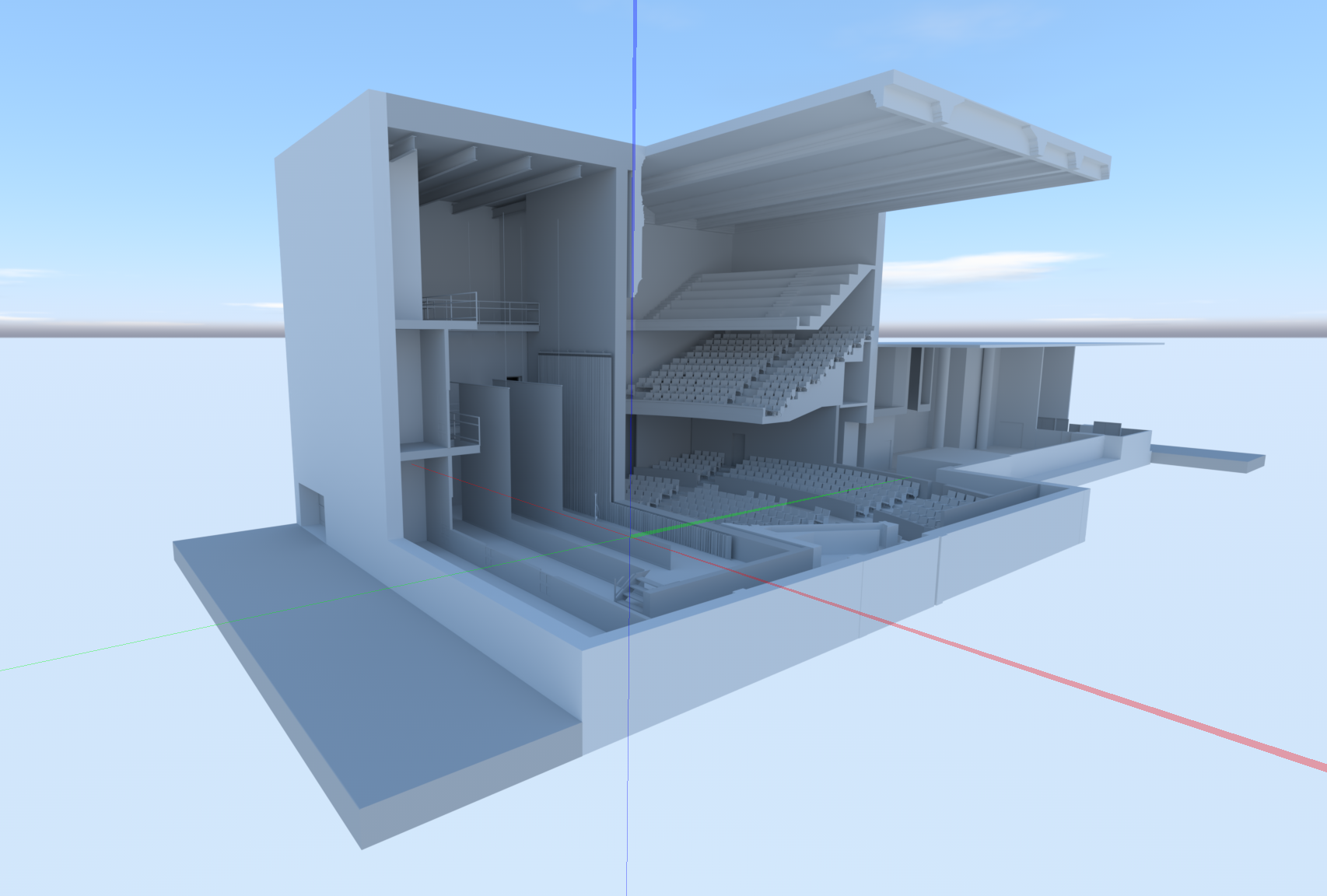
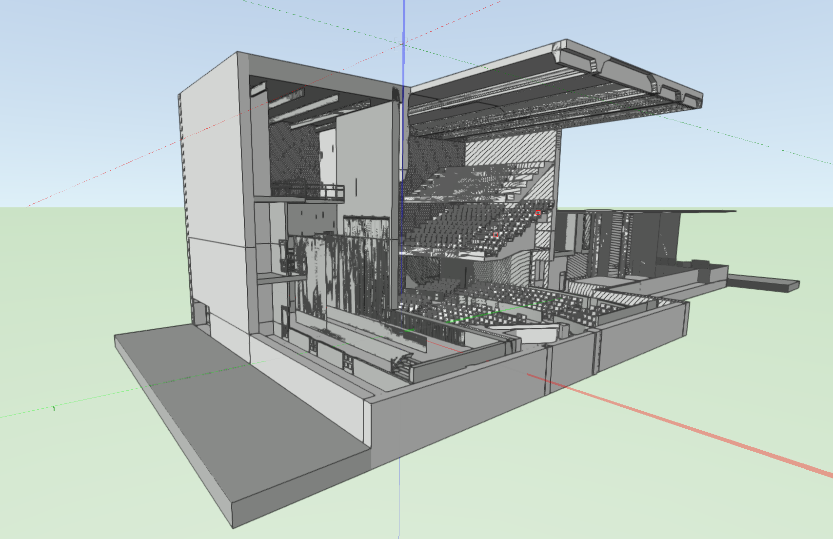
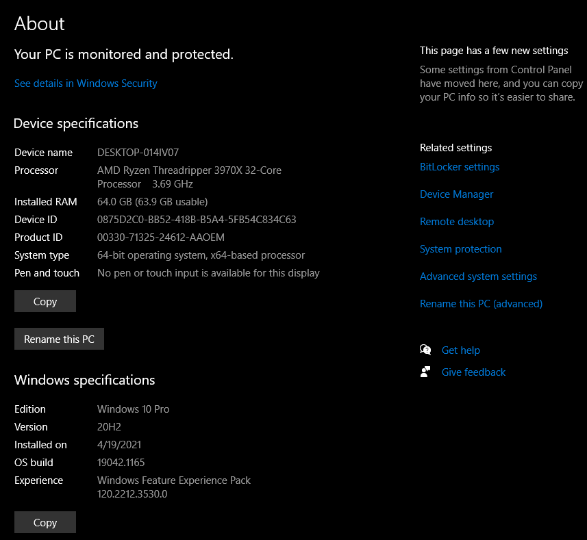
Here's some early screen grab testing right out of the box. Not scientific at all and no materials or lighting. 1. Preset: Redshift Interior Fast - 5 seconds 2. Preset: Redshift Interior Final - 30 seconds (and I'd say 15 seconds of that was denoising. I have to dig deeper, but at first glance - SHADED (formerly OpenGL) gives me a lot of lines and hatch artifacts (there is NOT overlapping geo), but as I zoom in more, it clears up. Haven't tried this yet in a Viewport, but I hope I can sort this as screen grabs of wide views to send to my designers is my all day every day 🙂 More testing to come. I usually run a few versions behind (still producing in 2020), but wanted to play with redshift. Machine specs below: TL|DR: (2) 1080ti on Win 10.


-

Slightly more than Drop Shadows Plan Drawing
EAlexander replied to DBruhnke's topic in General Discussion
Here's what I came up with: Made a horizontal section viewport of a model This will create a SECTION STYLE class for you to define the cut. I tweaked this and changed the fill color and line weight. You can adjust this to whatever you like. Added two directional lights: 1. set to 120 intensity and no shadows (this provides good strong light) 2. set to 40 intensity with shadows on (this provides the shadows and can be increased or decreased to make the shadows more prominent). In the viewport - set the Background render to custom renderworks and tweak the quality settings and turn off textures/colors. I also went into the lighting options and turned on Ambient Occlusion but lowered it way down. This can be off or increased if you like the look. Then I set the foreground render to Hidden line. File attached. My shadows are pretty faint in this screen grab, so adjust your levels on both lights to find the happy balance for you. shadowplan01.vwx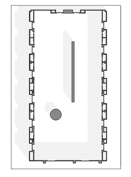
-
So it's weird and frankly, VW hasn't made it any easier to understand. This is the number one thing that confuses my students and clients as they are getting comfortable in the software. I think for basic 2d drafting, it is a good idea to stick to layer plane as it is predictable in how it lays on the ground as expected. If you have the "Convert layer plane objects to screen plane" checkbox checked in your symbol setup dialogue box, then you don't have to think about it. 2d objects will convert to 2d symbols and 3d objects will convert to 3d symbols as expected. Hybrids are somewhere in the middle as my video shows. Screen plane is very useful to me in my 3d solid modeling - for example, if I want to draw a wall or vertical LED screen for a show, I will usually flip to front view or right view and draw my profile and then extrude it in that view - layer plane wouldn't let me do that. I don't always just draw a plan and extrude up - lots of times I draw an object from the front or side and then push it into 3d. So it has its place and usage. What becomes confusing is that there is also 3d plane, working plane, symbol definition plane, screen aligned plane, and automatic mode for some drawing tools - so this is the part that really trips people up and I understand the frustration. The more you work with it the more you will be able to predict the unpredictability and work through it.
-
Worth noting - when you are creating a symbol and the dialogue box comes up - there is a check box that says something similar too: "Convert layer plane objects to screen plane". So if you have this checked - this would take care of your original problem. Once you check it - it remains checked until you uncheck it - so you only have to do it once.
-
Force custom printable area into One page?
EAlexander replied to EAlexander's topic in General Discussion
I did an HP plotter, but was surprised to see the download was over 1 GB. I did a custom installation and didn't add anything other then the driver. I don't want their "Manager" software and bloat. Would be good to know if there is a better way to deal with this. -
Force custom printable area into One page?
EAlexander replied to EAlexander's topic in General Discussion
Yes - adding the HP Plotter driver and creating a custom size within that printer did the trick. Appreciate your time and knowledge Pat.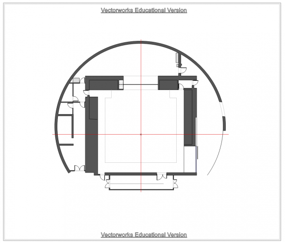
-
Force custom printable area into One page?
EAlexander replied to EAlexander's topic in General Discussion
Thanks Pat - I used to do exactly that with Manage custom sizes on Mac, but since switching to Windows, I can't find the equivalent. It's frustrating that Choose Size Unavailable in Printer Setup doesn't really do what the name implies :) I'm installing a driver for a HP plotter right now - I'll report back - thanks! e. -
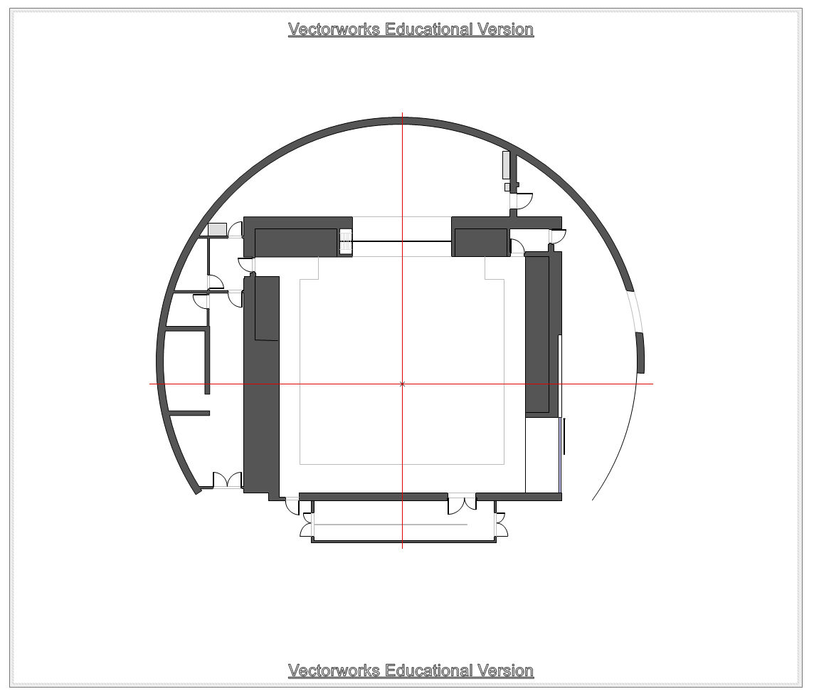
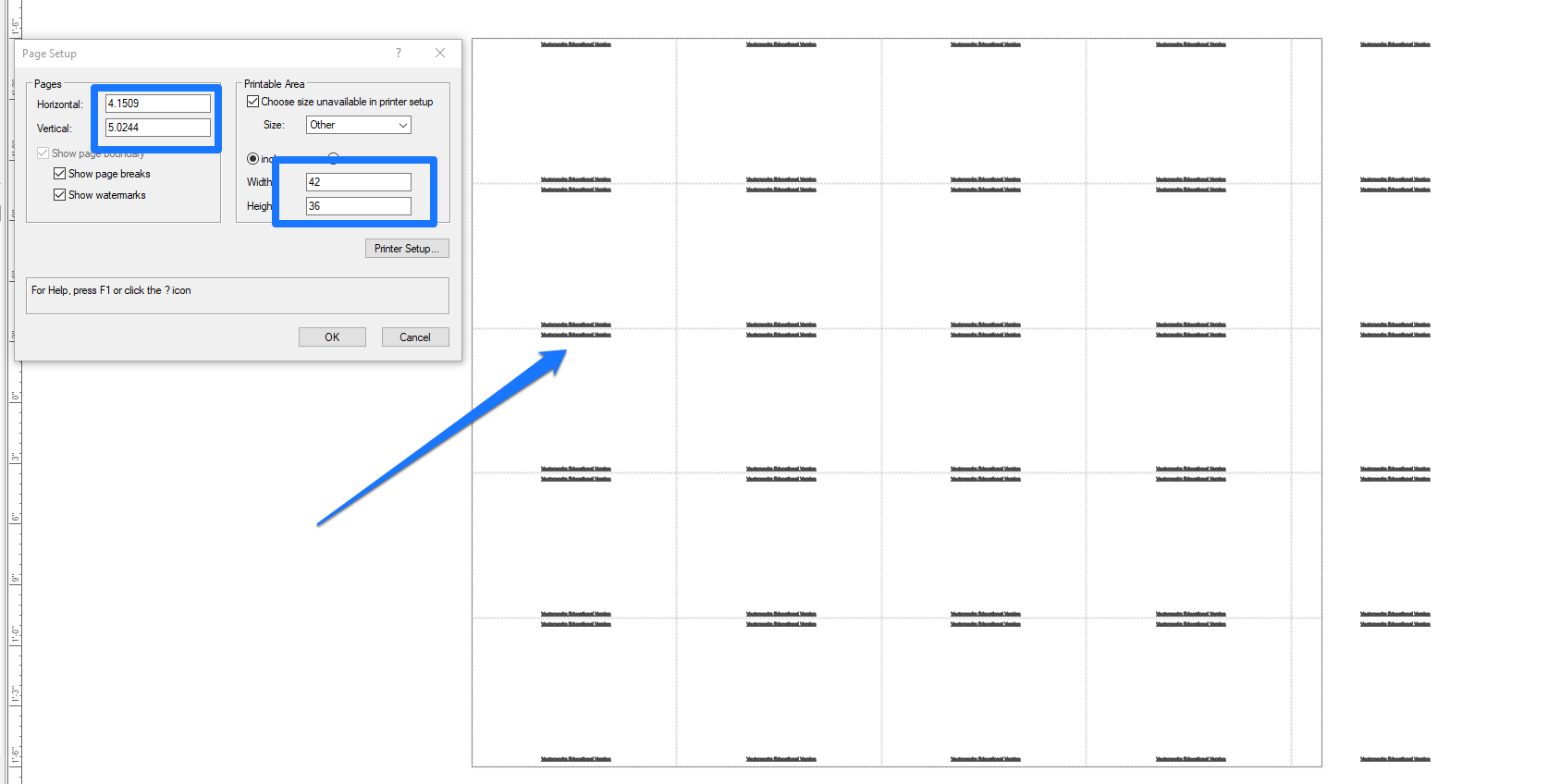
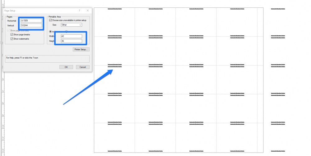
I'm working with a university to redraw their theater spaces into better drawings - since the base info comes from them, everything is watermarked with the educational mark (I'm a paid, professional user for many years). We're trying to do a non standard paper size for our sheets - the desired output is 42 inches wide x 36 inches tall. No matter what I do, VW won't let me pick this custom size and have it be one sheet - it keeps tiling smaller pages to make this up, even if I use "Choose size unavailable in Printer Setup". I don't have a plotter in my studio, so I can't set the printer settings to anything larger...but I thought "Choose size unavailable in Printer setup" was supposed to override this problem. The result of this tiling is that I am getting watermarks all over the drawing space, not just top and bottom. Please tell me I'm missing something simple here? Thoughts? See attached. I'm building this out in VW 2020 SP 3.1 on Windows 10. Thanks in advance for any help! e.
-
It should work like this: Your main drawing is living on a design layer(s). You create the first viewport of the whole space in 1:100 scale and send this to a sheet layer. Go back to the design layer and make a new viewport of the entry way detail in 1:50 scale and send this to the same sheet layer. Done. Alternatively, you can make the first viewport and send it to your sheet layer in 1:100. Then, duplicate this viewport and double click to edit the crop to focus on the entry way - hit the orange button in the upper right when the new crop is correct. Then, with this new viewport selected, go to the Object Info Palette and change the scale to 1:50. Position it where you want on your sheet layer page. Make sense?
-
@canthony - be sure to also run the PURGE command. This will get rid of any extra resources that you don't need. i.e. if old symbols/textures/etc. are still in your resource manager but not in your drawings, these will count towards file size - Purge will get rid of anything that takes space but isn't in your drawings. It shows a list of what you have and you can choose what to purge and what to keep before deleting anything.
-
Hi Mark - I'm not the guy for this (I work in Entertainment) - but just wanted to say I love your work. Really clean but inviting designs. Hope you find a great candidate soon.
-
We use Cinema4d with the Corona Render engine or the Redshift render engine depending on the needs of the job. Twinmotion is an option as is Enscape. These are based on game engines and don't get as photo real as the raytracing renderers, but are more accessible and easier to learn. The VW roadmap says Redshift is coming to VW, but no timeline given and I imagine it will take a while to work the kinks out.
-
B - the slight bump as indicated above is good - will make it feel more like drywall or plaster then a perfectly smooth wall. To get the sheen thought, you probably want to change REFLECTIVITY to Mirror and then hit the EDIT button. Take reflection way down - like 5-10% and then play with the blurriness. Best to experiment on this shader in a separate file to keep your overhead low while testing. Note - the blurry reflections can slow down render times dramatically, so watch that and make sure it's worth it visually. e.
-
Hi - I would approach this differently - see attached. Let me know if that helps. e. VW_TP_01.vwx
-
Can you show a visual of what you're trying to pull off?
-
Just chiming in on the C4D side of it all - yes, you could flatten this out in Cinema very easily since you can manipulate points, edges or polys there. However - it would not respect proportions and would distort the size/spacing of vertices making it not an accurate option.
-
Problems of transparency with export of sweep into step-file
EAlexander replied to virk's topic in General Discussion
Not sure what the problem is, but you could try converting the sweeps to Generic Solids before exporting. So select all sweeps then go to MODIFY>CONVERT>CONVERT TO GENERIC SOLIDS. See if that helps. The fact that you're sweeping a line instead of a polygon or polyline might be the problem, but I wouldn't think that matters. -
If I understand correctly, what you need is to create a SECTION VIEWPORT through the center of your alcove from the View menu. This will give you a section through the middle that will show the depth, and profile for the shelf.
- 1 reply
-
- 1
-

-
I've got a student having this exact issue. She's on the educational version of 2021 Designer (not sure which service pack) and these GL menu items are greyed out. There is also no texture options on the OIP in the Render tab - not just greyed out, but actually not present at all. @Tamsin Slatter any thoughts or ideas? Thanks.
-
There is no gallery on this forum, but I bet if you post and ask for constructive criticism, you'll get it. The community is pretty good around here. I'll give you some feedback.
-
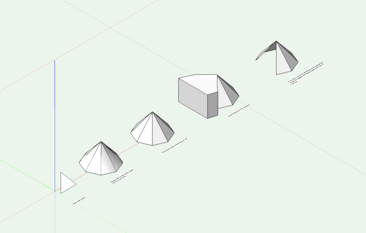
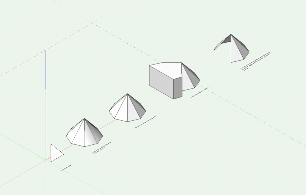
You could also build this as a sweep and that would let you adjust the segment angle, so you can control the "resolution" of the arc. Lower number = smoother curve.