sww1235
-
Posts
33 -
Joined
-
Last visited
Content Type
Profiles
Forums
Events
Articles
Marionette
Store
Everything posted by sww1235
-

Structural Member and Framing member steel beam profile not selectable
sww1235 replied to sww1235's question in Troubleshooting
It apparently was something in my user preferences, as I reset them after an email to tech support. -
Structural Member and Framing member steel beam profile not selectable
sww1235 replied to sww1235's question in Troubleshooting
The issue is affecting me in multiple modes, not just column insertion mode. Unfortunately, I do not have any fellow students to check the file. I am an Electrical Engineering student learning Vectorworks on my own. I do lighting design and architectural concepts for fun in my spare time. I have tried reinstalling vectorworks completely, as well as updated to SP4 that just came out. Does anyone know where those particular files are stored, and could they give me a directory listing to compare to? -
Structural Member and Framing member steel beam profile not selectable
sww1235 posted a question in Troubleshooting
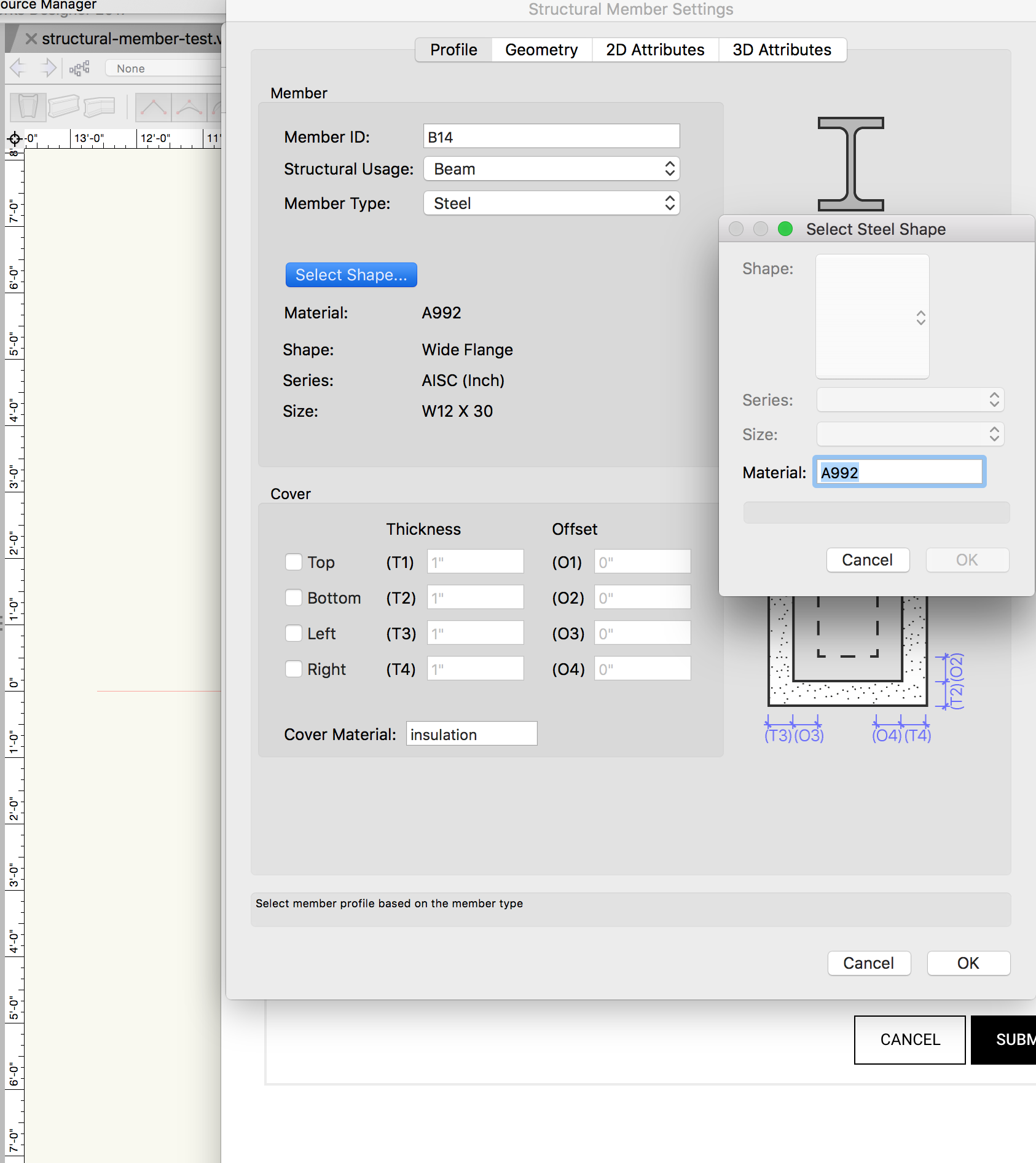
I am attempting to use the structural member tool to create steel beams and columns. When I attempt to select a shape using "select shape" with steel material selected, all the boxes are greyed out. I cannot select the shape, series or size, but I can enter a material. Currently the properties dialog box for the structural member is reporting that I currently have a Wide Flange W12x30 beam selected from AISC series but I have no way to change that. I have confirmed this issue in both an existing file and a new file. I have attached the new file and a screen shot of what I see. I also checked through the resource browser and do not see any structural profiles that I could import that made a difference. structural-member-test.vwx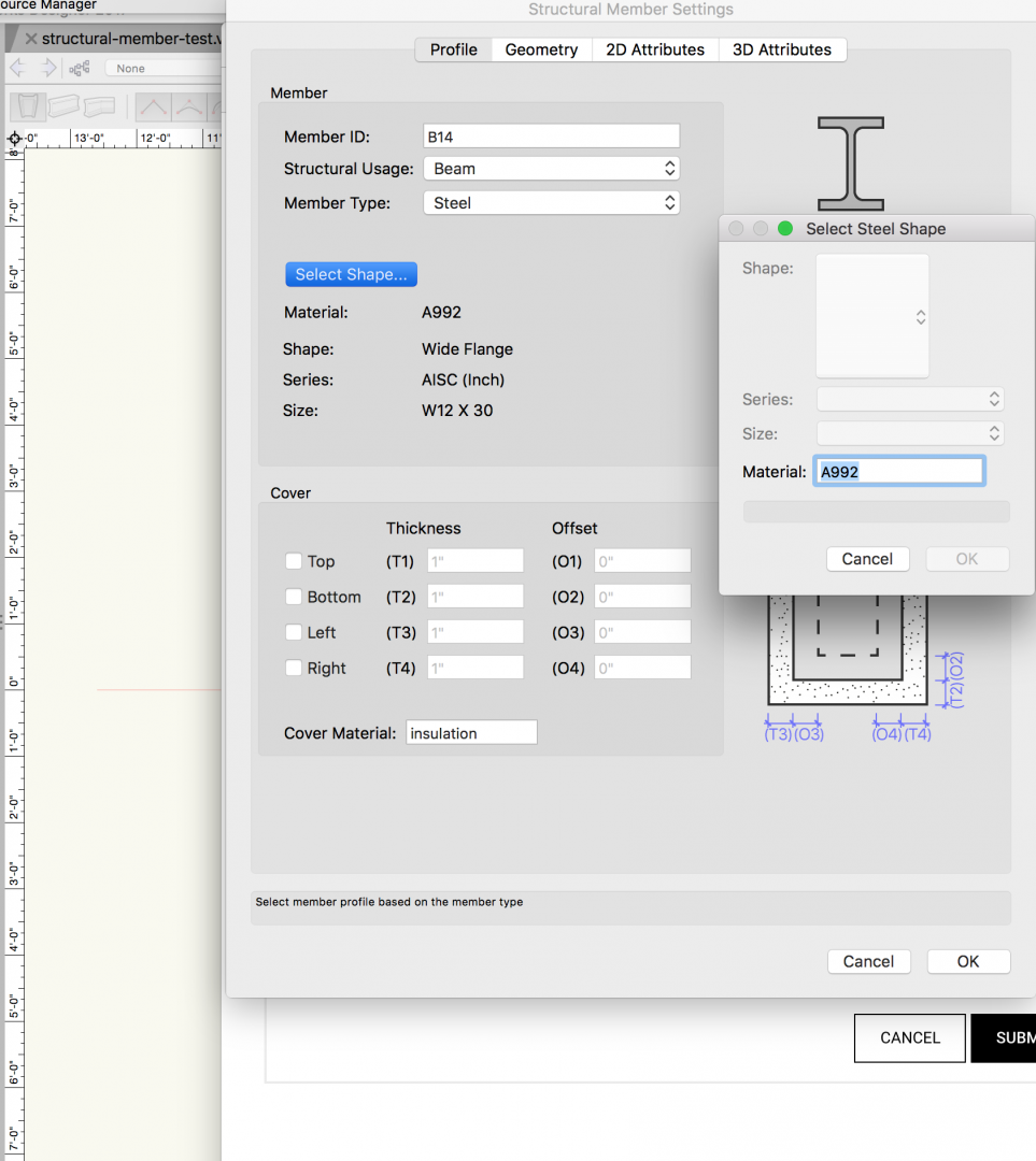
-
@Luis Calderonyes, a curtain wall would probably work better for that particular application.
-
in 2017 at least, there is a lambda value listed for wood framing + mineral wool insulation, but I doubt it would be sealed properly for passivhaus based standards.
-
I don't have a lot of experience with vectorworks, but I would recommend using a fully 3d workflow. This way you can use vectorworks to automatically generate the sections and elevations as needed in viewports. Vectorworks worksheets have a way to include window symbols in the worksheets. Hopefully some other users will chime in. This section of the forum is a little less traveled, being further down the main page. If you have any specific questions, such as how to generate a specific elevation or section, or properly scheduling walls and doors, I would recommend posting in the general questions or architecture forums as those see a lot more traffic.
-
Arc Length Dimension Tool
sww1235 replied to Kevin McAllister's question in Wishlist - Feature and Content Requests
As a related issue, I would like the arc length and angular dimension tool to work directly on curved walls. It seems silly that the regular dimensions work properly on rectangular walls, but as soon as you use curved walls, you have to add additional arcs and then dimension off of that. Also curved walls don't work at all with the "dimension exterior walls" tool. -
Rigging Weight Calculations
sww1235 replied to bbeanan's question in Wishlist - Feature and Content Requests
@Pat Stanford Yes I agree. I would love for trusses to automatically calculate weight of cables and fixtures attached, and have chain motors pick up weights and other info through a connection to the truss. I would be fine with only two point calcs at this point. Like Energos is only an estimating tool, I think a truss weight and chain motor capacity estimating tool would be very helpful, although it would need to be designated that it is not a substitute for proper mechanical engineering and rigging knowledge. -
Hello: I have a building with several insulated interior walls and so wanted to create a new "Object Boundary Type" as shown under Edit Wall Style -> Insertion Options -> Energos. I have created a new type, but I cannot figure out what the parameters R S External and R S Internal are used for. Even the units are confusing, sq ft F h/Btu. What are these parameters used for? Thanks in advance. Edit: After a bit more googling, these units appear to be inverse heat transfer coefficient, but what I cannot figure out is why this additional value adding to lambda and R/U values. What values should I use for interior walls? Interior meaning two conditioned spaces on either side of an insulated boundary. The wall style has a lambda value determined by components.
-
Thank you very much. That did the trick.
-
Hello: I used the create spaces from walls tool to generate spaces in my project. I also went through and created a few custom spaces and modified a few of the automatically generated ones to be a little more precise. In total I have 25 useful spaces. When I created a worksheet to list spaces, there are 5 spaces listed that have zero area and no name. I am not able to select them through the custom selection tool, even though it reports 30 objects. When I have every class and layer turned on, along with show/snap/modify on both classes and layers, I am only able to select the 25 useful spaces. Is there a way I can get rid of these useless spaces without completely redoing my document? Thank you
-
@Alan WoodwellThe even weirder thing is that I have 2 additional solid sections, both assigned to the exact same class with the exact same settings, and they pick up on the texture just fine. Its only this new one that does not. I tossed the file with issues in dropbox as it is too large to upload directly to the forums. The class in question is Furniture-Built In-Bookshelves. https://www.dropbox.com/s/aafnnap56li56js/wizards-tower.vwx?dl=0 Thank you everyone for all your help. This forum is probably one of the most helpful I have ever participated in.
-
Wow, I wonder why. I needed the 3d polygon in order to get the correct z height for the extrude so I did not test with another piece of geometry.
-
@Alan WoodwellThanks for the tip about the deform tool. It worked out well after some playing around with it. A followup question, I have assigned the resulting generic solid to a class with a wood texture assigned. However the generic solid is rendered as wireframe only. I have checked the render tab and it is set appropriately to class texture and document default. Any suggestions?
-
Hello: I am attempting to create a curved built-in bookshelf using extrude along path. I created the profile as a 2d polygon and am using a polyline converted to a 3d polygon in order to gain a z parameter, as the path. This is a fairly simple path and profile, yet it takes upwards of 30 minutes to generate, all the while vectorworks is frozen and I get a spinning beach ball. Luckily I am able to use other applications on my computer as normal, but vectorworks is reported as "application not responding" until the process is complete. Once the EAP operation is complete, the file is still very laggy in both 2d and 3d views. In an attempt to make the file less laggy, I converted the EAP object to a group of 3d polygons and simplified them by 1 inch, but this results in very weird texture rendering unlike the EAP solid. This does almost completely eliminate the lag associated with the EAP In the file attached, the path and profile objects are on the Extrude Primitives layer, the extrude test layer contains the completed extrude, and the polygons layer contains the grouped 3d polygons generated from converting the EAP object. EDIT: I know that my hardware specs are not the greatest, but vectorworks runs fine except for this issue as long as I don't try and do crazy OpenGL or renderworks fanciness. EDIT 2: I realized I forgot to upload the file and attach it, and in the process I realized that it is 236Mb. This would potentially explain why it is so laggy, but why would an EAP object, 2 polygons and the extracted group of polygons be over 200Mb. My other file that I was originally trying this in is only around 155Mb and contains loads more geometry and PIOs. Dropbox link to file: https://www.dropbox.com/s/izc6u2d5m4koqob/extrude-test.vwx?dl=0 Thanks in advance.
-
@markdd Thank you very much. I will have to give it a try.
-
Would this work without Vision installed?
-
I filed a bug report on this back in December and have not heard anything back from vectorworks support. I have the generated crash logs as well if that is helpful.
-
That was the trickery I mentioned. Thanks for all the help
-
@Wes GardnerThank you very much once again for your complete answers. Do you know if the countertop/backsplash will work properly with curved walls or will I have to use some trickery?
-
Hello All: I am working on a building with completely circular walls. I want to have the kitchen partially on the interior of the curved exterior wall, however none of the PIO cabinetry tools appear to snap correctly to curved walls. Is there anything recommended for this situation? I have looked at the InteriorCAD plugin but cannot tell if it would work in this situation. Or should I just brush off the basic 3D modeling tools and create loads of custom symbols. I would like to have all the reporting tools available so I would like to use the PIO tools if they can be made to work. Thank you
-
@Alan WoodwellThank you so much for the example files. I missed the importance of having the display extents above cut plane turned on.
-
Hello: I have used the extrude along path tool to create a custom curved builtin bookshelf, however on top/plan view it is not showing up with my chosen fill. I found this thread about converting it to an auto-hybrid, however none of the settings I have found in the auto-hybrid settings, allow me to use the fill in top/plan view like my wall objects. I would assume there is something small but important I am missing. Thanks in advance
-
I figured it out. Somehow the perspective drop down was set to custom perspective vs normal which is what I normally use. Thanks for all the help.
-
As a note, I created a second sheet layer and viewport of one floor in 2D/plan and the view filled the viewport and the resulting scale makes much more sense. i cannot figure out why the 3D viewport scale is so off.