


Jose E. Calderon
-
Posts
41 -
Joined
-
Last visited
Content Type
Profiles
Forums
Events
Articles
Marionette
Store
Posts posted by Jose E. Calderon
-
-
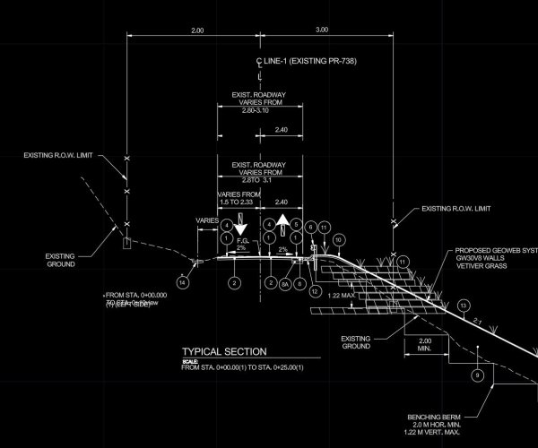
It it possible to createa road on a site model with a complex cross section profile?
I have to design a road with a compelx road - gutter - shoulder profile. Look image attached . The examples in VW Land design only offers a road with a simpel square gutter. Any help?
-
Thank you.. ! It was a invisible class.
-
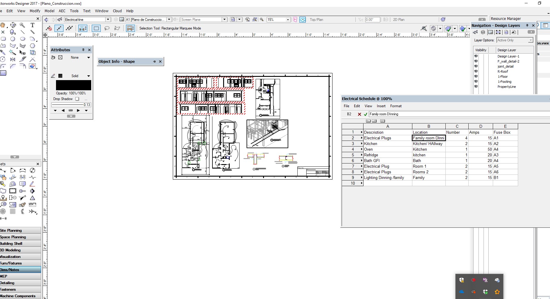
For some unknown reason, a created worksheet no longer displays on my sheet. I find the worksheet listed on my resources but I lost it in the sheet layer. What is the way to search for this lost items??? I opened the worksheet but it no longer displays in the page.
Here is a link to th e file
https://www.dropbox.com/s/km6thwwbjw59yvk/Plano_Construccion.vwx?dl=0
-
Thank you for your contribution. I know this much.. You are using separate modifiers limits for each of the three sections. Use one modifier encapsulating all three sections
-
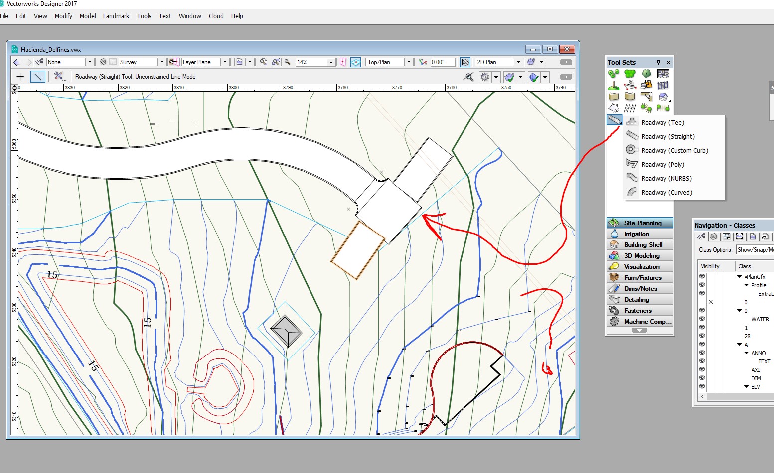
I posted a previous post on this subject but got a limited response. I am simplifying the question this time. It is about the Road Tee command from landmark. I don't see any use of this tool. I align the Road Tee with a straight line , but this is not connecting to the straight line. Therefore, what is the use of this command? Can anyone come here with a good working example? I need to create a network of roads and parking lots connected the peripheral, but not getting too far. I am expecting everything to work 3D and with a site modifier over a site model.
-
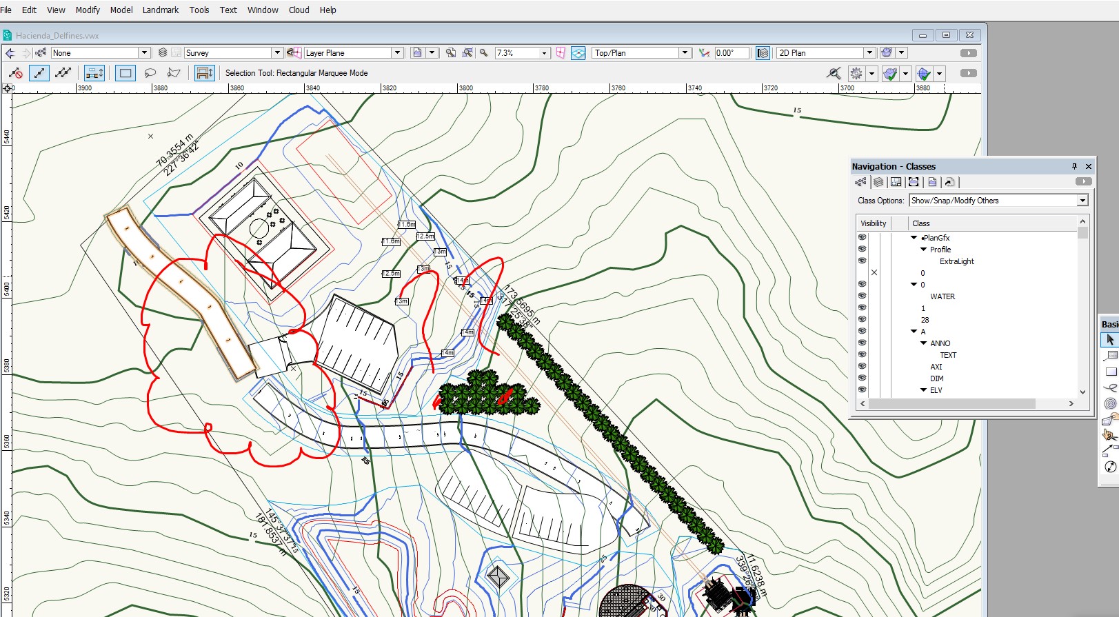
I have gone a long way . Need to design my interior roads and parking space. But I am not getting too far. To many problems not been able to join and site modifiers conflics. Please help.
here is my problems. In my design , I have 2 roads and 2 parkings. I need to draw the Road T to access from main road to the parking lot. It looks like there are several ways to get there, but I am not getting very far.
I use Polyline to draw 2 roads. Then I use the Road Custom command to do the parking area with the 2D Parkign command to create the parking configuration.
But , I am not able to join the roads in a T. I created the 2 roads across my property , but not able to get the ROAD Tee to fit and join the roads. I must be doing something very wrong and the documentation doe not help.
Here is the link to the VW file.
https://www.dropbox.com/s/ro2ke5nzk1dqqh0/Hacienda_Delfines.vwx?dl=0
-
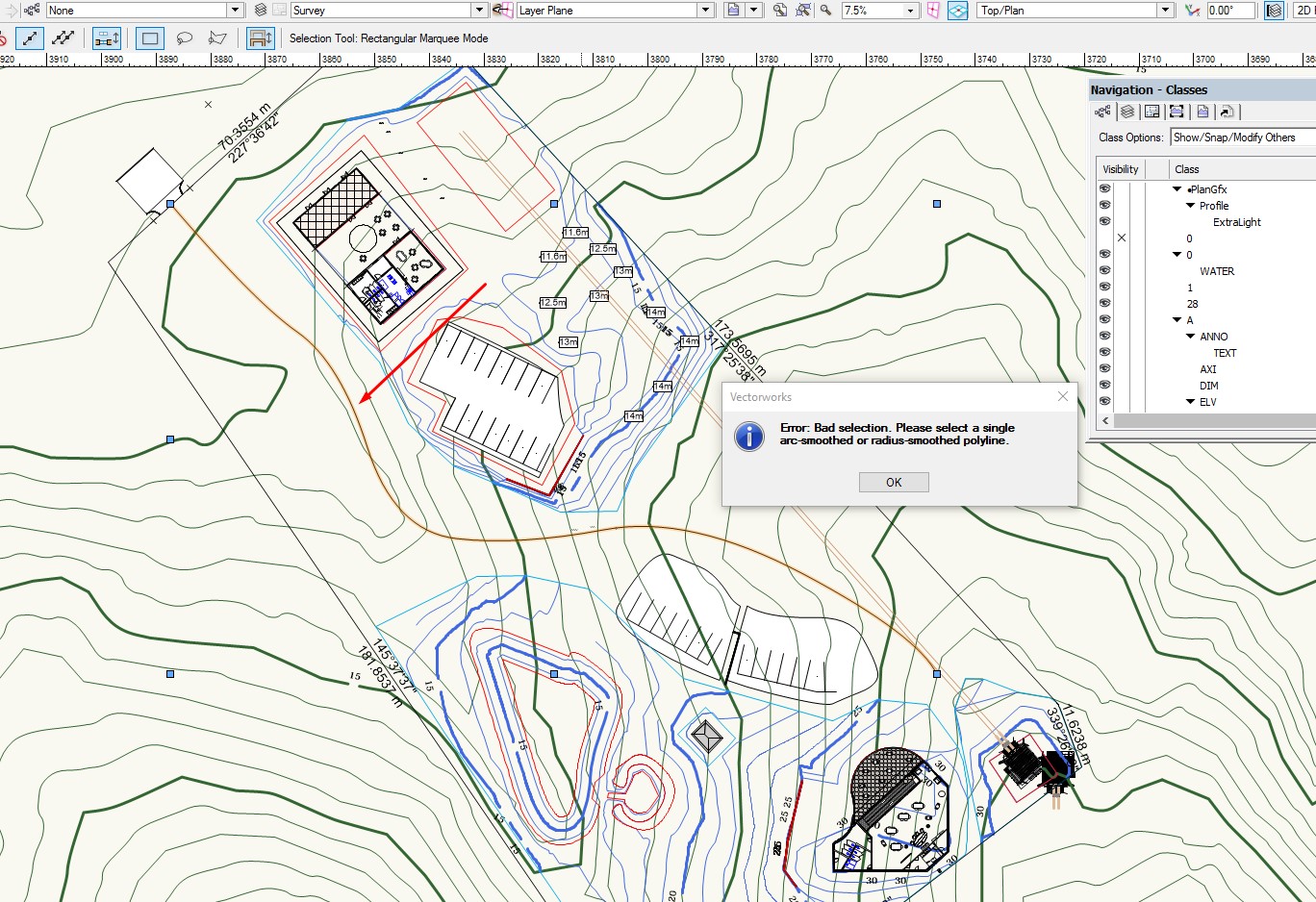
Thank you but not sure what do you mean. The instruction says that to use the Polyline tools. There is only one polyline tool in 2D , therefore, how I make a polyline with Arcs only?
-
Why I am not able to use the Stations on Polyline command from Landmark?
-
YEs but will rendering isometric views will work?
-
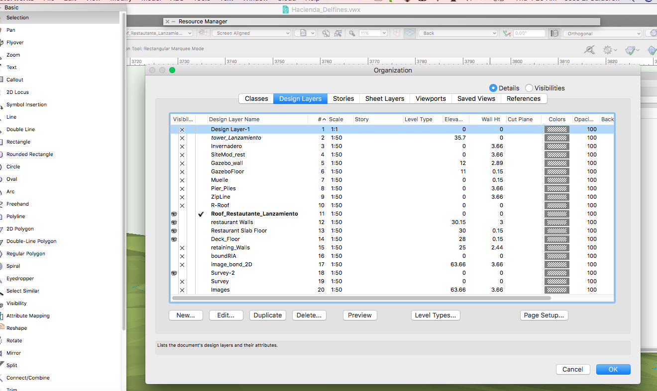
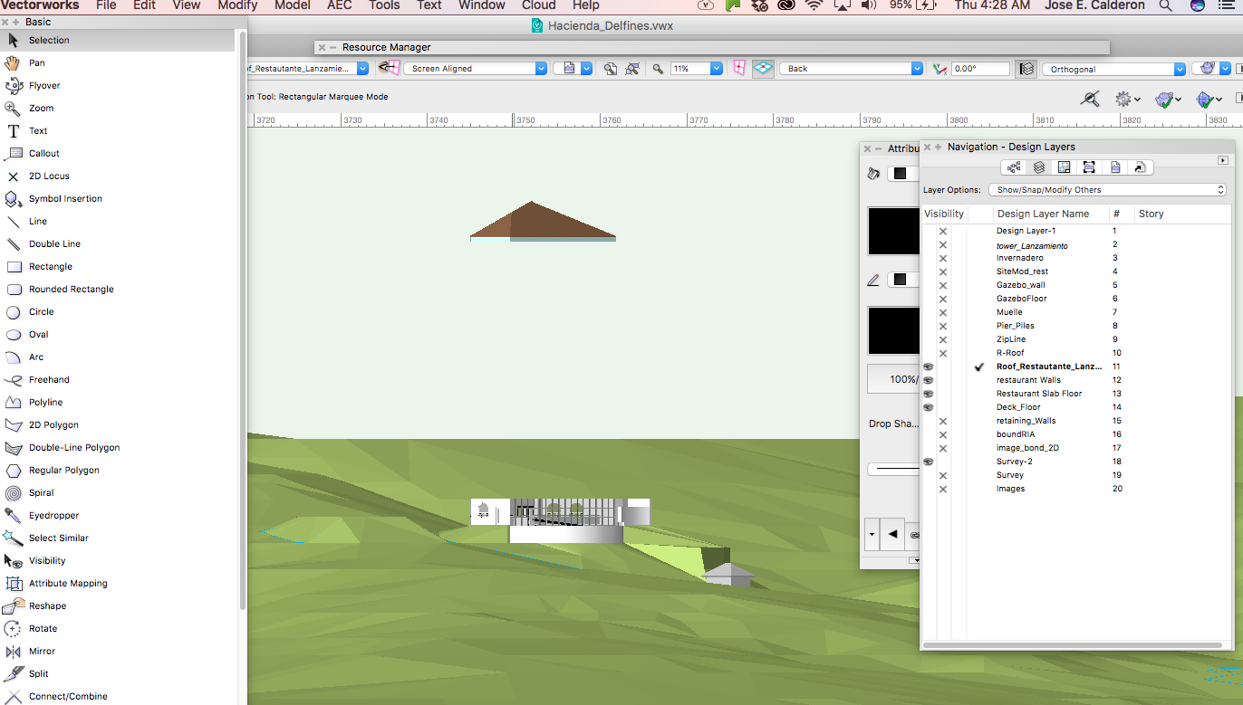
I need help with my Created roof from the walls. I do not know why the roof is residing several units above the wall. There is nothing that I tried to relocated the position.
Here is a link to the VW file
https://www.dropbox.com/s/ro2ke5nzk1dqqh0/Hacienda_Delfines.vwx?dl=0
-
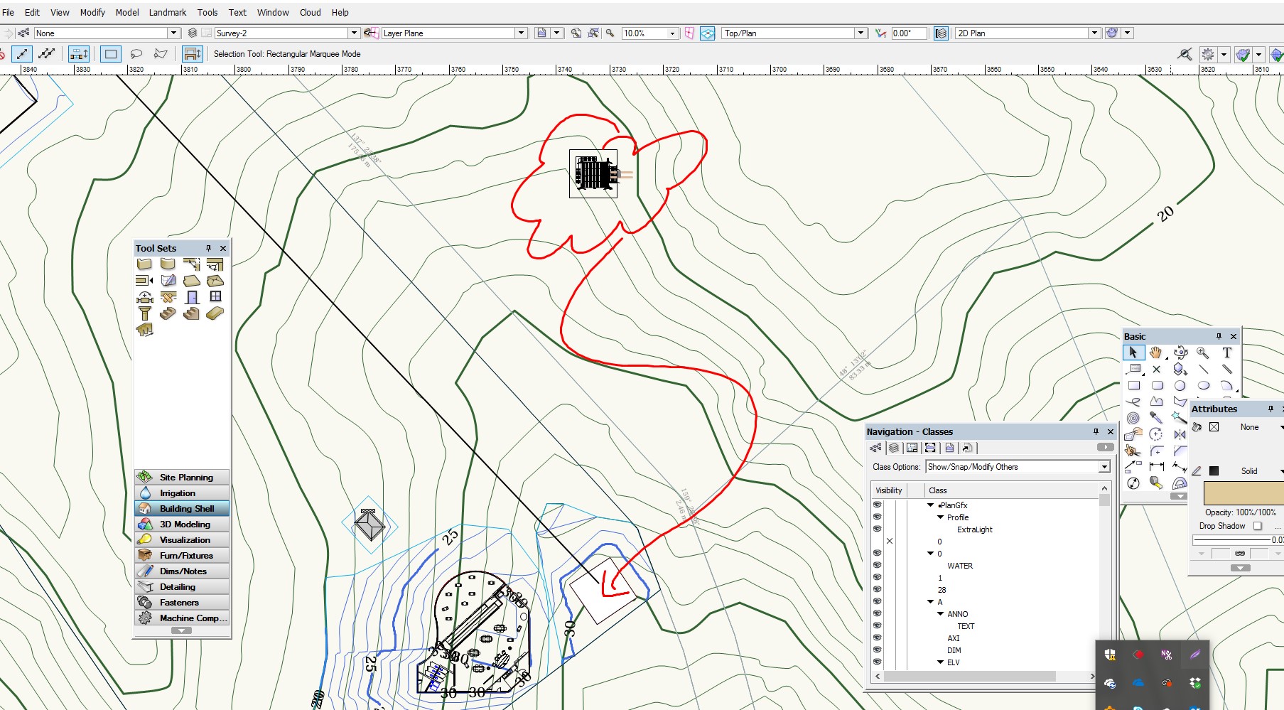
I created my survey site model in one file and a building in a second file. From the Survey file, I attached the building file as a reference file.
But Now , how do I translate and rotate the imported layer so that to register in the exact location over the site model? I see the reference layer , but it is placed way out of place.
-
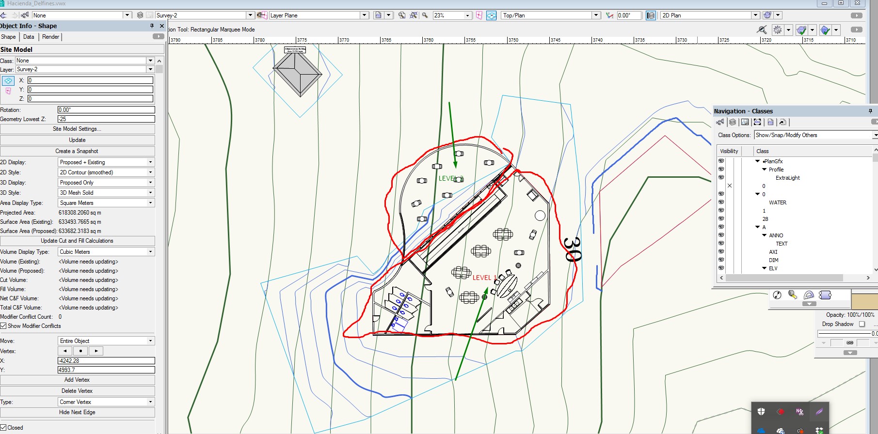
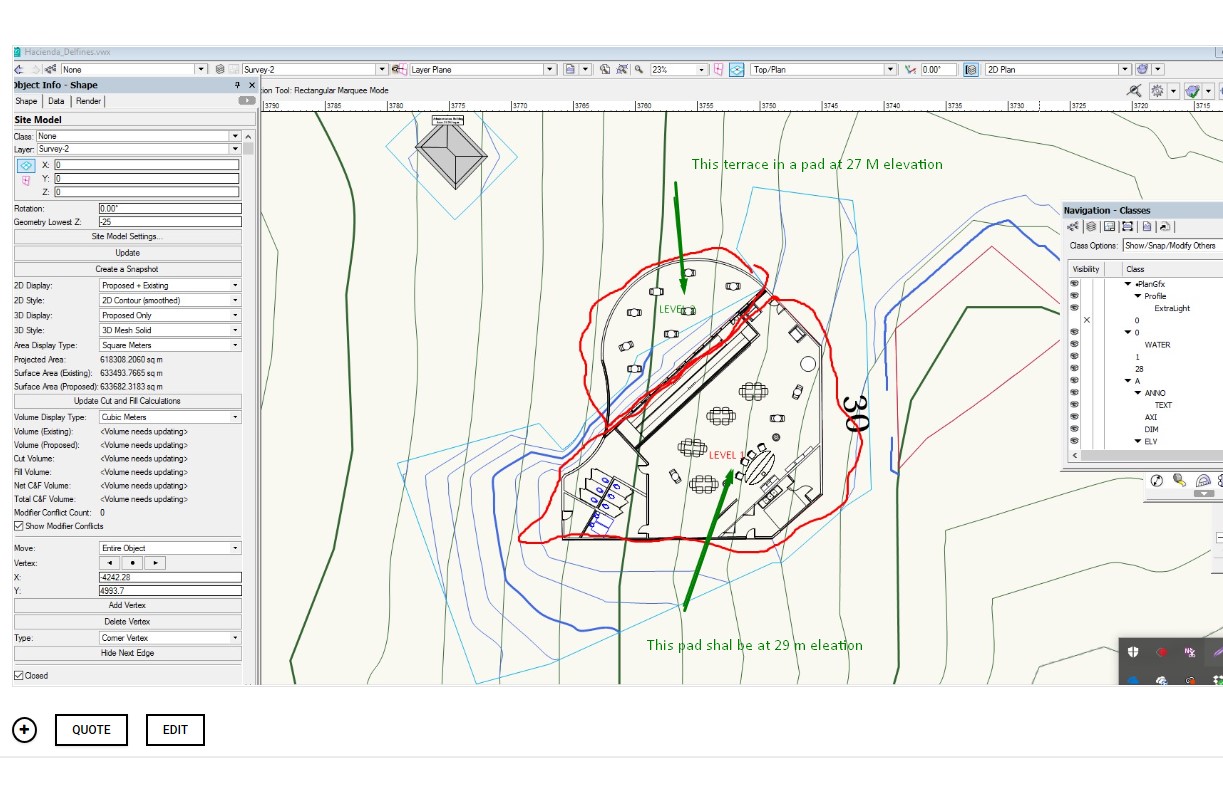
I am working with getting refine skills in Site Modeling. I have a small building resting over a steep hill . I designed one floor building with a terrace at one level and the remaining area steps up into another pad elevation. I have trouble setting the Site Modifier for Pad with retaining wall and normal pad. The problem that I face is that the pad are joined together alone the line that separated both sections of the building returns an error.
What technique I need to apply?
IS there a better technique to tackle this situation. I sea a lot videos but they don t really take into account Pad modifiers that are aligned one next to the other touching together.
Here is a link to the VW drawing...
https://www.dropbox.com/s/ro2ke5nzk1dqqh0/Hacienda_Delfines.vwx?dl=0
-
Can yo post a link to the video?
-
I need help mastering site modifiers tools. I have trouble getting the Boundary limit around a pad.
I have set a boundary site modifier for the property limit. Proposed Site Model looks good. But I entered a second smaller grade modifier inside the property surrounding a site modifier pad. But the second boundary limit is not acting as expected. The pad is created but the contour is modified all the way to the outside boundary limit of the property.
https://www.dropbox.com/s/ro2ke5nzk1dqqh0/Hacienda_Delfines.vwx?dl=0

-
Ok,.. got it.. Small retainer wall modifier in a hidden layer.
-
I am working on a site model. I created a site modifier in my mother that later erased. But I can not find why the proposed still shows a grade modification. I have checked the only modifier present is the Boundary modifier of the lot. Please help. Here is the archive
https://www.dropbox.com/s/ro2ke5nzk1dqqh0/Hacienda_Delfines.vwx?dl=0
-
Thank you...Allan.. I just realized that the proposed is a separate snapshot/. This was not expected.
Unfortunely , I erase the PROPOSED site plan snapshot. Is there a way to recreate it without having to enter the original data and do a Site Model again? here is a link to the job.
https://www.dropbox.com/s/ro2ke5nzk1dqqh0/Hacienda_Delfines.vwx?dl=0
-
I thank you for the details. I have several questions.
1) How you set up the contour lines and colors. Did you set this up (Color and the line styles) . Why is not site modifier making this automatically? For example. The blue for proposed and then the segmented green line in all areas where contour is modifies. My application is not even closely making any changes. In fact. The modified drawing in 2 D is nto been change at all and I do not get any modified in 2D.
2) How was the text size change? There is nothing in the modified site model parameter settings about TEXT size.
3) I am constantly getting a computer application Termination and crash every time that I make a 3D change.
4) I was not able to change your version of .VW file to change from 2d top view to isometric 3D. Application just hangs. I was able to change the view but only after restasting the computer.
-
Why my proposed site model is not rendering the text over the mayor contours? Also, can not figure why the proposed contour is not overlaid over the existing model.
https://www.dropbox.com/s/ro2ke5nzk1dqqh0/Hacienda_Delfines.vwx?dl=0
-
Thank you for the reply. But this will not due. I want to separate what is the shore line and forward in a light blue versus green for the upland. The slope wont do it in fact.. a long portion of the upland is already very flat .
-
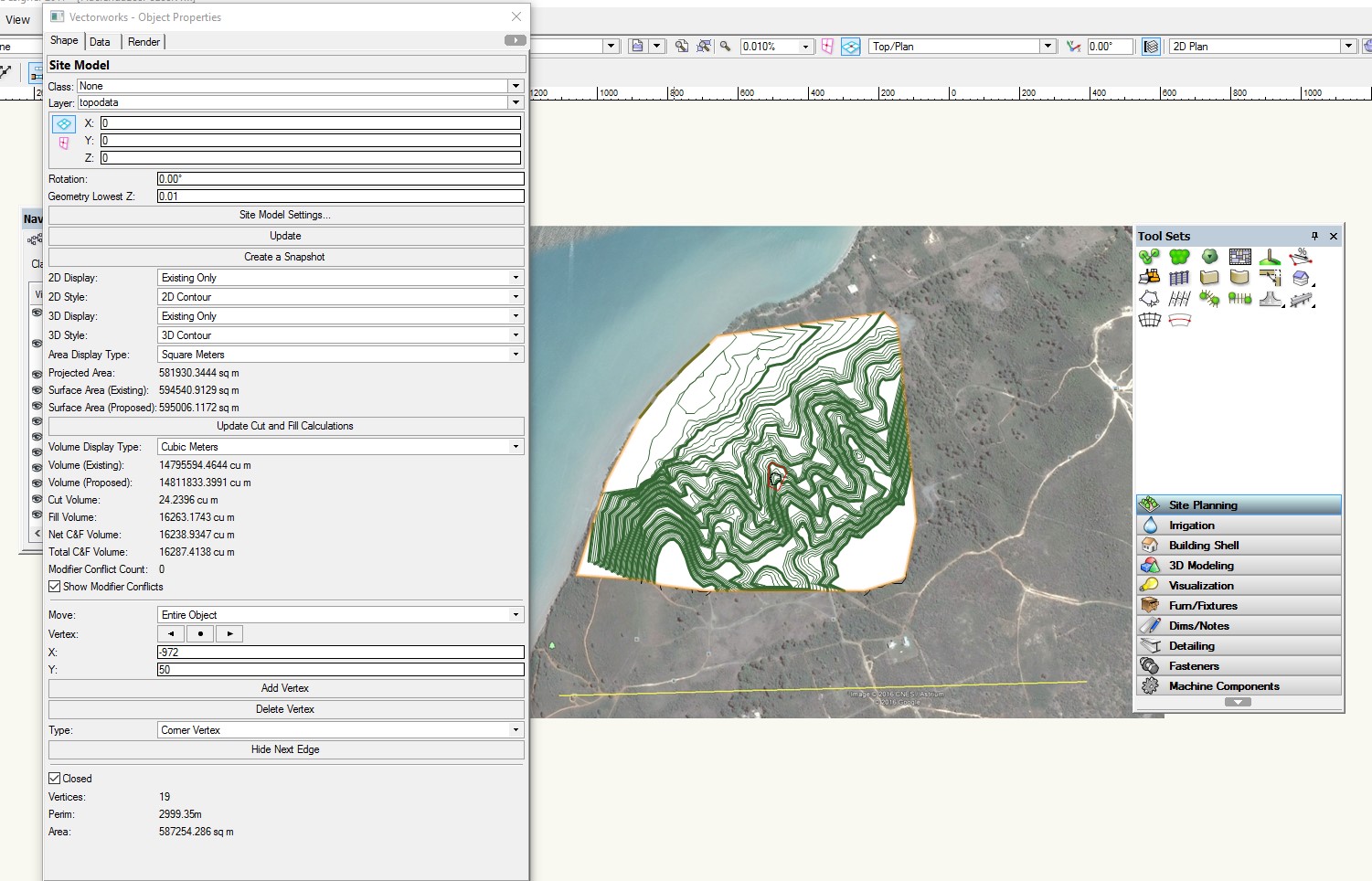
I have a site model if a area alone the water front. I am set contour data for areas on the water to be below 0 (negative levels) I will like this surfaces site model to render blue color to allow clearly differentiate between upland and wetland.
Here is a link to the VW file
https://www.dropbox.com/s/ro2ke5nzk1dqqh0/Hacienda_Delfines.vwx?dl=0
-
Are the heights in your original at he correct height? If this is so, make sure that when scale the original data asymmetric (X and Y ) only to the new scale.
-
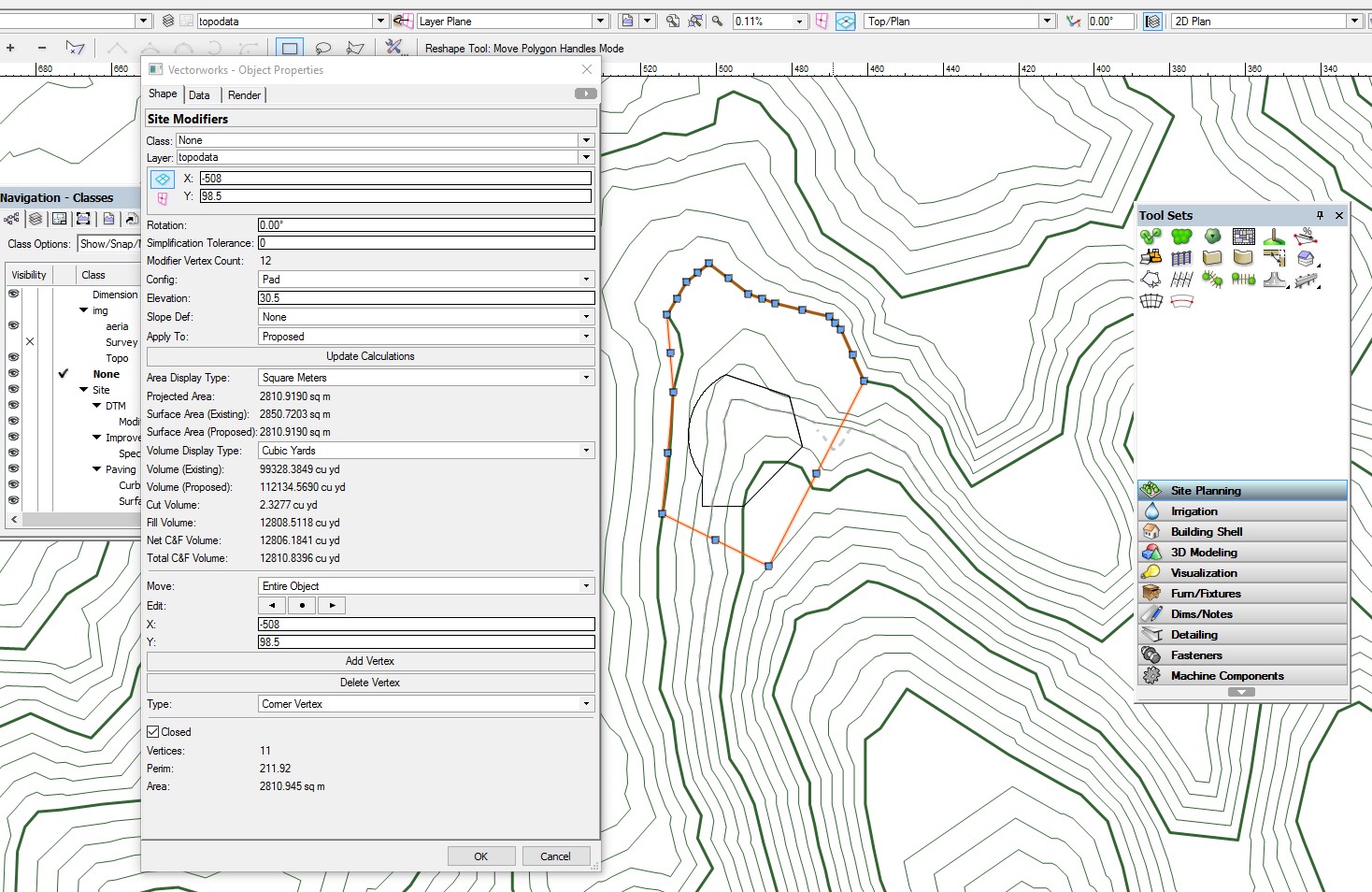
I have no idea what I am doing wrong. I created the Site model follow by a polygon and a site modifier pad. I se the pad height but the contour lines are not modified at all. See That I have a small polygon and a modified pad around the pad.
Here is a link to the file
https://www.dropbox.com/s/es3twjlnpsus5ct/HaciendaLosPozos.vwx?dl=0
I also notice that the contour lines are all solid. This is contrary to the documentation showing the original to be dashed lines.

-
This is a simple and consider a common scenario but not able to get a solution.
I created a Digital site model using 3D Polygons that where converted to 3D loci. I am not happy at all with the resulting Contour site model. I realized that I needed to add additional 34D polygons data in order to enhance the resolution of the site mode.
But I am not able to return to the original 3D polygon not the 3D loci data. I double click the edge of the contour site model, but all I get is the Site model parameter windows. I do not want to change the model using modifiers. I just want to recreate the site model.

Convert text in 3D to loci point
in Site Design
Posted
I have a drawing with text in 3D space. the text reads the elevation. I need to convert this text to a point loci which will alloe me to build a site model. File attached.
surveryNaranjo4.vwx