


nahekul
-
Posts
51 -
Joined
-
Last visited
Content Type
Profiles
Forums
Events
Articles
Marionette
Store
Posts posted by nahekul
-
-
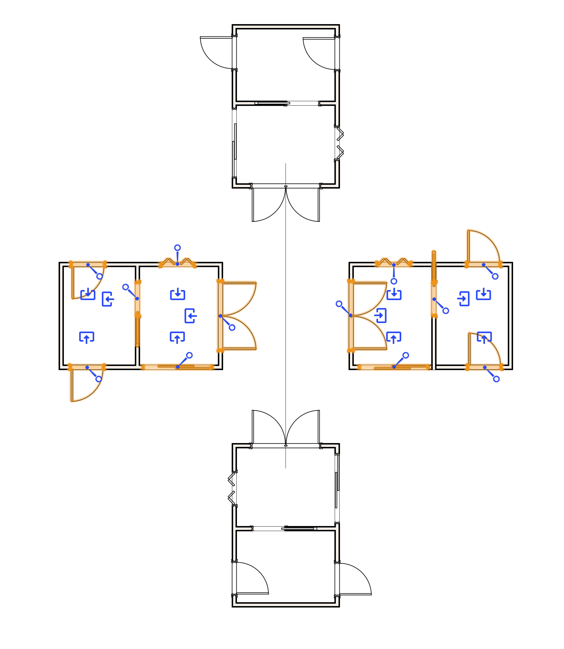
When flipping or mirroring doors that are inserted into walls, the program seems to reverse the direction of the doors but the handing remains the same.
For example, the outward swinging door still says out but the graphics is showing the reverse.
However, rotating them seems to maintain the correct door orientation and graphics.
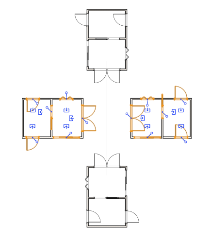
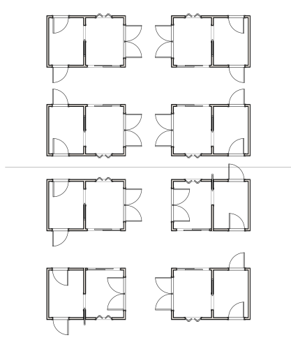
Flipping/Mirroring works in symbols. However, once the symbol is exploded, the doors are reverted to the incorrect orientation.
Interestingly, only the symbols that were supposed to be flipped are messed up (top right and lower left).
The lower right one is correct. (I assume that even though it was flipped, that orientation was achievable through rotation so it is not messed up).
-
This looks to be resolved by editing the style, changing the configuration to "by instance" and then changing back to "by style".
After that, replacing the 2 different styles will change the window's operable sides.
-
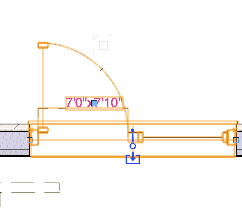
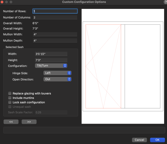
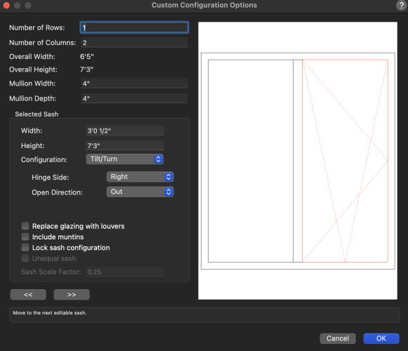
With the update of 2024, the new feature of interactive handing was added.
This works well with the standard configurations but I can't figure out how to get it to work with custom windows with a center mullion.
In 2023, I can set up the custom window and flip the operable side to the left or right.
In 2024, the operable side only stays on one side and I cannot flip it to the other side.
Even making 2 window styles, one with operable left and one with operable right, it does not show correctly once inserted into the wall.
-
It allows me to select the 3D custom symbol and the preview shows the selected symbol but does not actually apply it outside the settings.
Also, it seems like there is no way to turn off the infill.
-
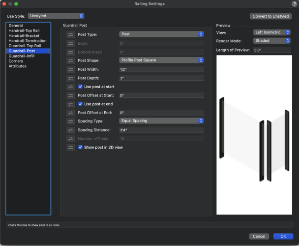
The new railing tool seems to be missing the option to use custom symbol as the post/bracket profile.
Without this, there is no way to have any railing that is not just a straight extrusion. (eg. belly railing or angled railing)
Will this feature be added back to the new railing tool?
Old Railing Tool:
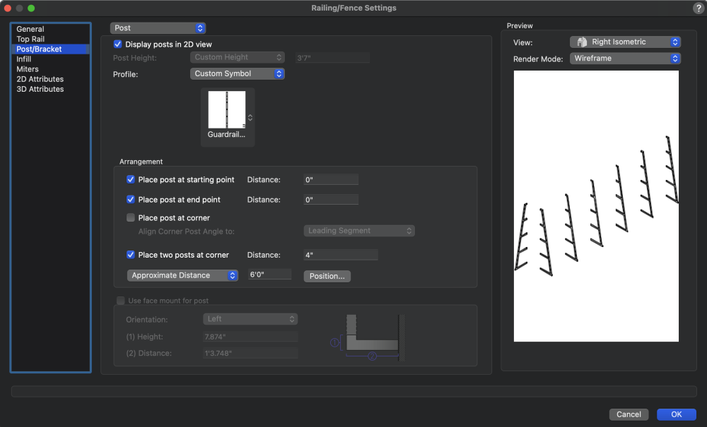
New Railing Tool:
-
 1
1
-
-
You are correct. I must have misremembered how this works before.
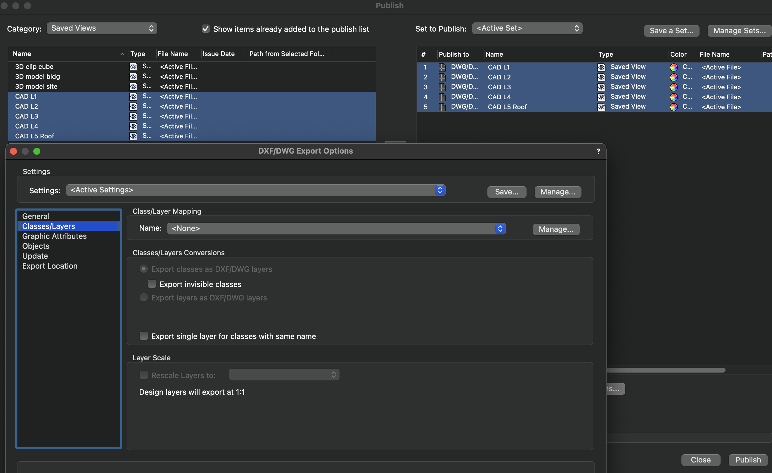
Exporting doesn't work for saved views when I try to select it.
The only way this works is to go to each saved view and export it manually using design layers.
-
It's when I try to publish saved views. (Using File>Publish)
However, when I export the saved views individually it works. (Using File>Export)

-
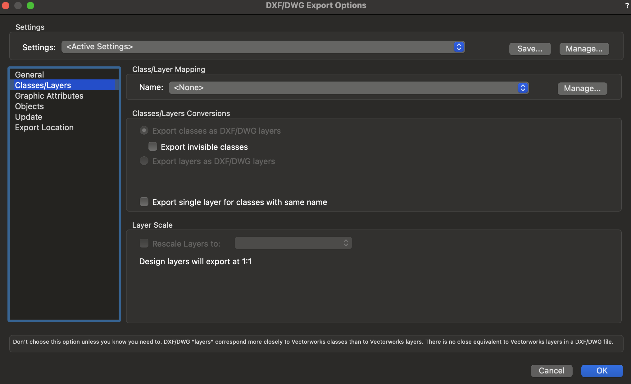
How come "export layers as DXF/DWG layers" is grayed out now?
We used to be able to select that option.

-
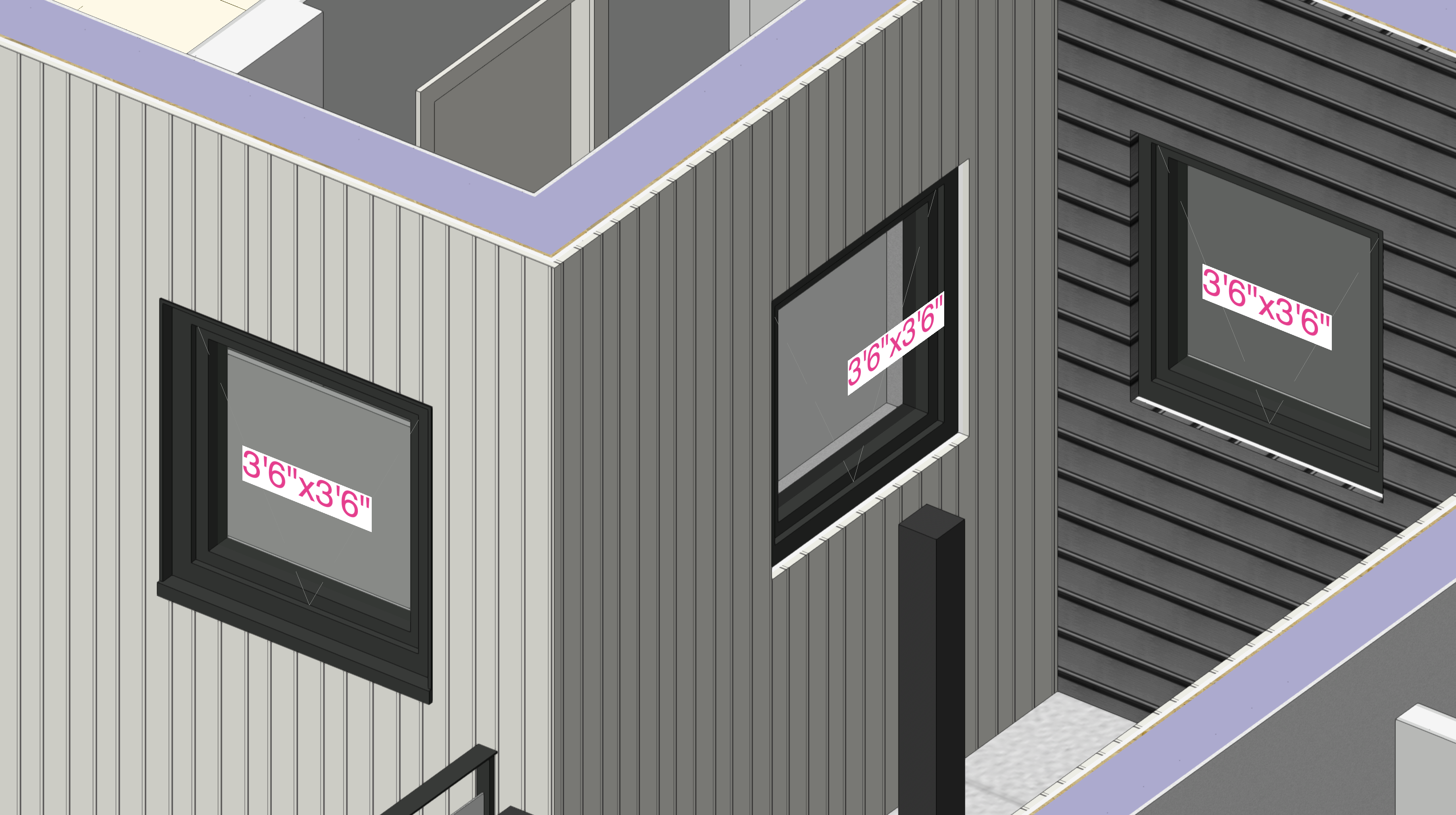
We've tried using wall closures but the problem is we cannot control the colour of the wrap independantly from the cladding.
For example, if the exterior cladding is white, we cannot have the wall closure as dark.
In the image, the left window is how we want the trim to work. (Currently done with lintel as a workaround. This doesn't work with corner windows.)
The 2 on the right is with wall closure with the cladding wrapping in, which is not what we want.

-
 2
2
-
-
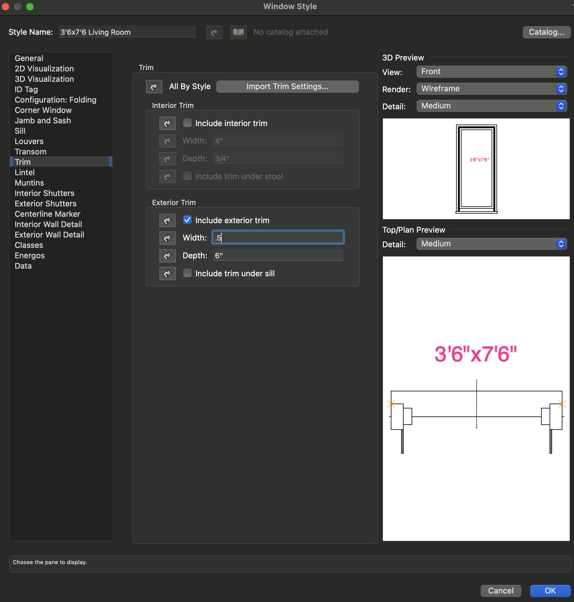
Is there a way to move the exterior/interior window trim to the edge of the rough opening/jamb instead of the face of the sash?

-
This is still not working in VW2023 for us.
-
9 hours ago, Tom W. said:
You can change the size of the marker using the 'Scale Factor' parameter in the OIP but this will change the size of all instances of the marker so you need to create an unlinked copy of the marker
Thanks Tom. That's what we'll do for now as a workaround.
15 minutes ago, Tom W. said:Sorry I see where we're misunderstanding each other now. I meant when you have the same Section-Elevation Line object displayed in multiple viewports: you change one instance of that object + all the others change as well. I thought this was what @nahekul was talking about... Maybe I should have said 'sub-instance' 🙂
Yes, if it is the same section-elevation line displayed in multiple viewports, then the scale factor parameter affects all of them (in different viewports).
Matt, the video only shows that different section-elevation lines can have different scale factors.
-
2 hours ago, Pat Stanford said:
You can convert text fields to numbers using the Value() function, but not if there is non-numeric text stored in the field. So Value(19.09) will work, Value(19.09 sq.ft.) will not. If all the text fields are formatted identically, it may be possible to extract just the numeric part to use in Value() using the Mid/Right/Left/Substring functions to remove the non-numeric parts.
Thanks Pat, this worked great. Just being able to change the text to value helps a lot. The non-numeric text such as the unit marker can be added in the suffix in the cells so it's not an issue.
2 hours ago, Pat Stanford said:Or if might be possible to write a worksheet script that would give you the area of objects in a specific class or with a specific record attached that overlap the Space object.
If this is possible, it'll greatly help speed up entering all the areas for each space manually.
-
On 3/27/2019 at 12:26 PM, Matt Panzer said:
Glad to help! 🙂
The "printed" size of the markers should be the same across viewports regardless of the viewport's scale. IOW, a marker seen in a 1:50 scale viewport should be the same size (as seen on the sheet layer) as the same section line marker in a viewport of another scale.
Is there a way to change the size (or style) of the marker on different viewports?
For example:
We usually have a larger-scale viewport of the plan with the section markers at scale 1.
We want to show a key plan with the section markers at a scale of 0.2.
How can this be done?
Same with the grid lines and reference markers and tags.
Is there a way to convert them to world-based instead of page-based like it used to be able to do?
-
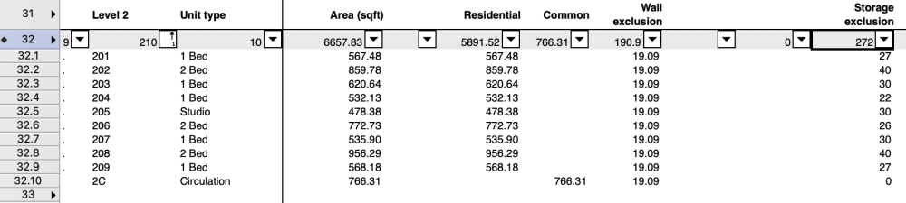
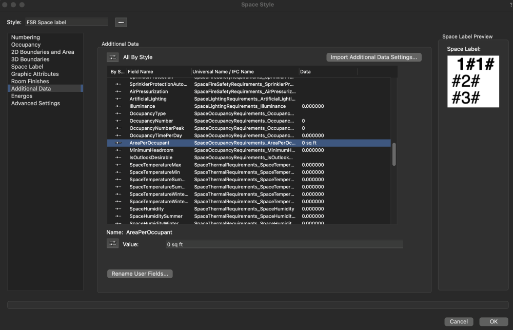
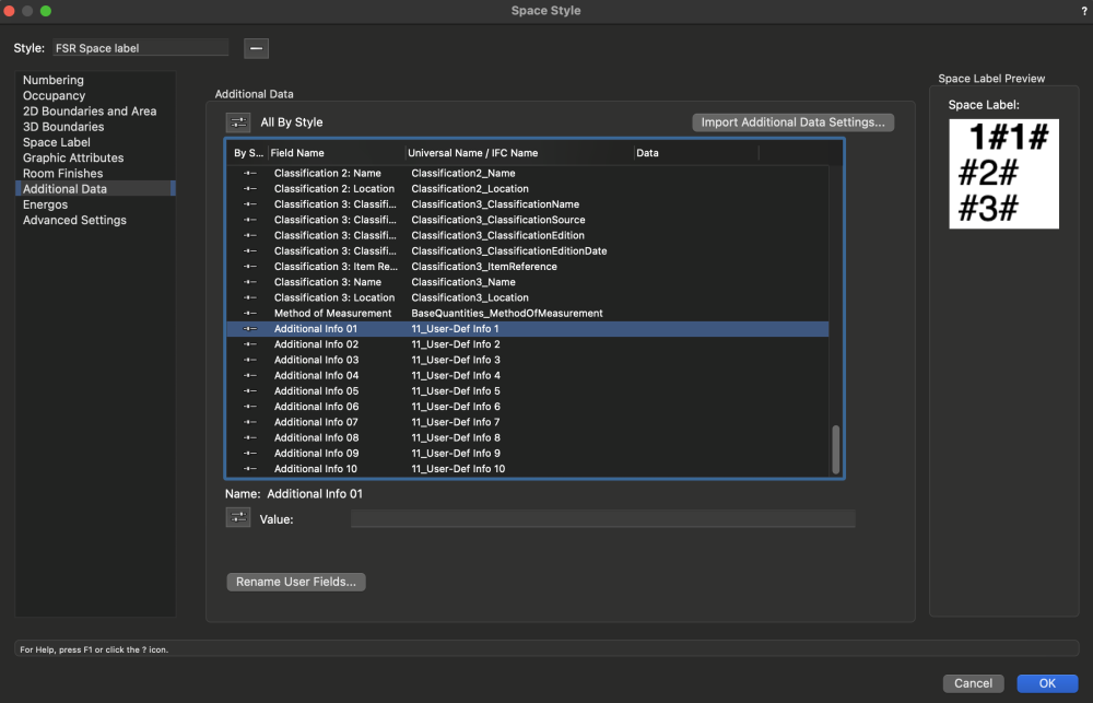
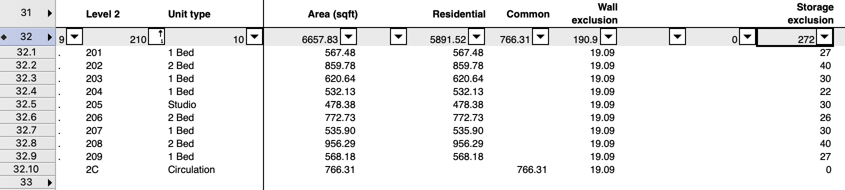
Is there a way to link another polygon's area or line length to the Space object's "net area" or "additional data" parameter in the OIP?
This would be really helpful for area calculations and area exclusions that the municipalities usually want to see on the floor plans.
For example:
Unit 201 has a gross floor area of 567.48 sqft.
There is an in-suite storage room exclusion of 27sqft (drawn as another polygon)
Currently, I am entering this exclusion manually in the additional data parameter (AreaPerOccupant) in the space object OIP.
Then I subtract this area from the gross floor area to get the net area in the database header.
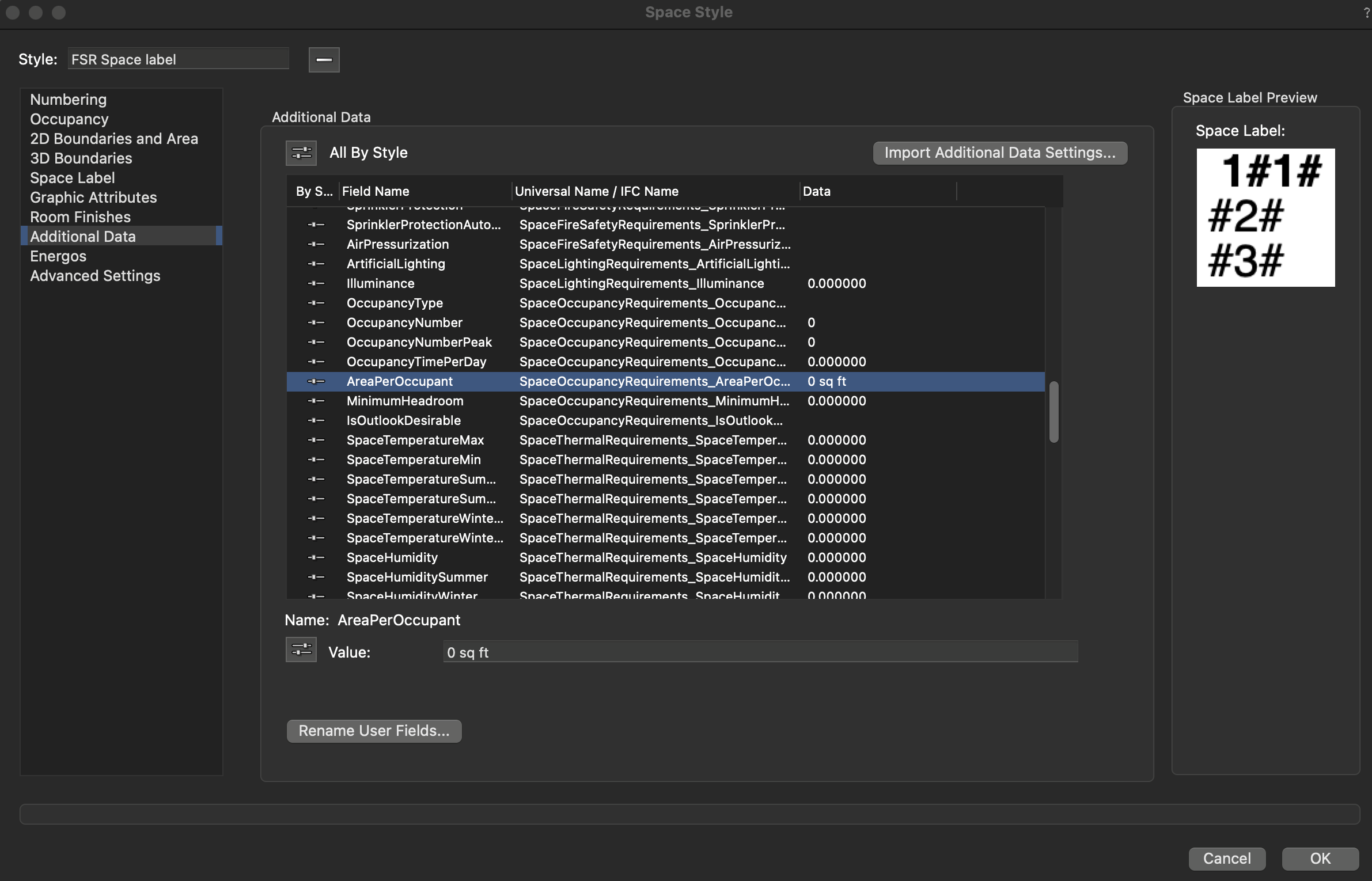
Note:
This is the only parameter that returns "sqft" as data in the worksheet database.
All of the "Additional info" fields return a text data, and I don't see a way to change the data type
If I can change the data type for the "additional info" fields, this would allow for more calculation options in the worksheet database headers.
-
Thanks Tom, looks like that was the issue.
-
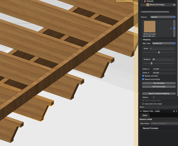
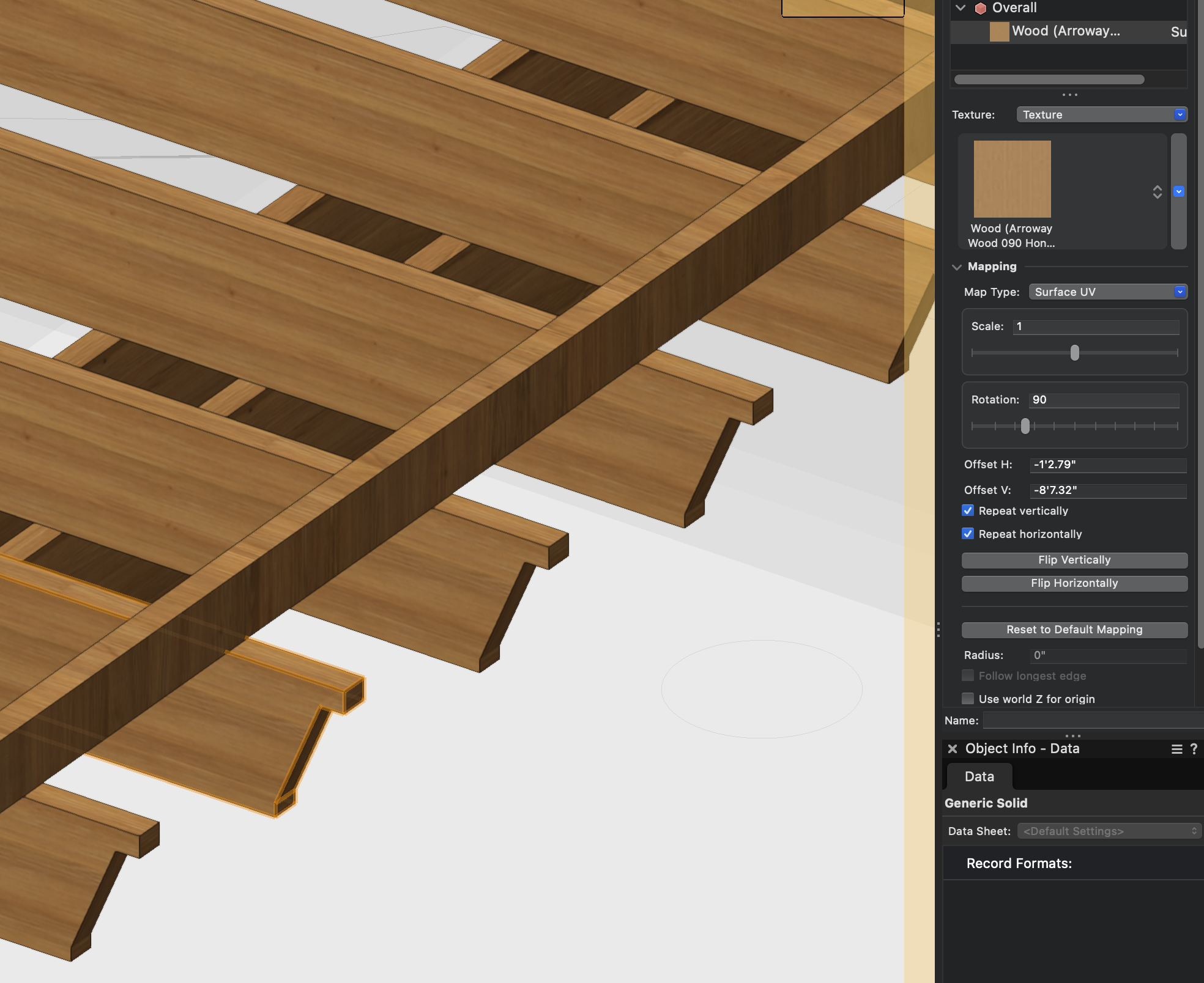
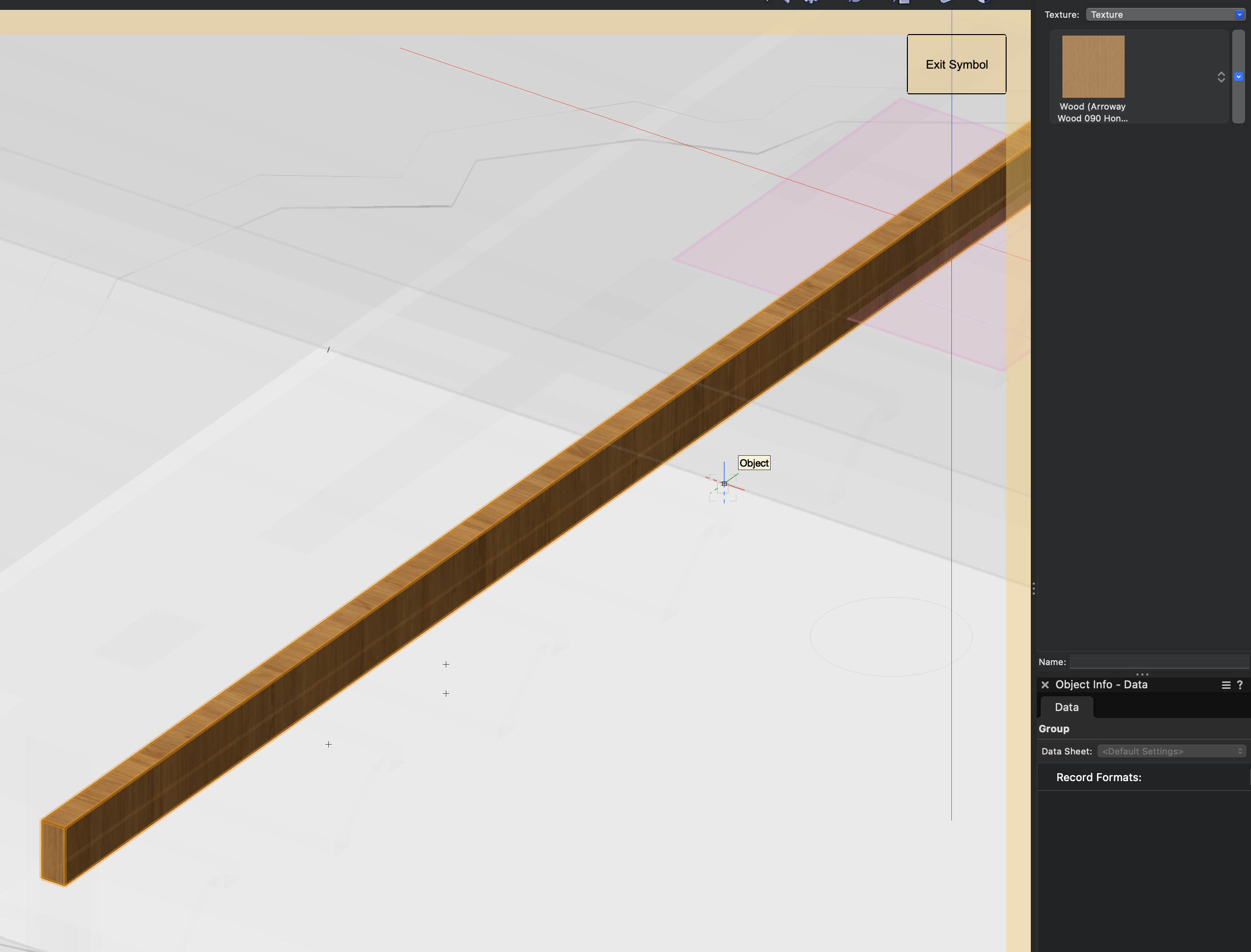
A generic solid under the OIP render tab has the mapping options to change the rotation and scale of the texture.
However, in a symbol, there doesn't seem to be a way to change this.

-
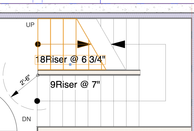
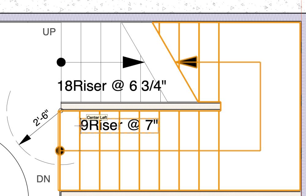
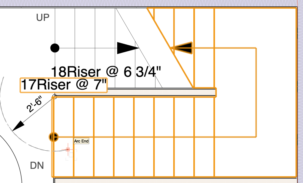
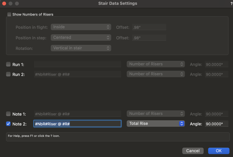
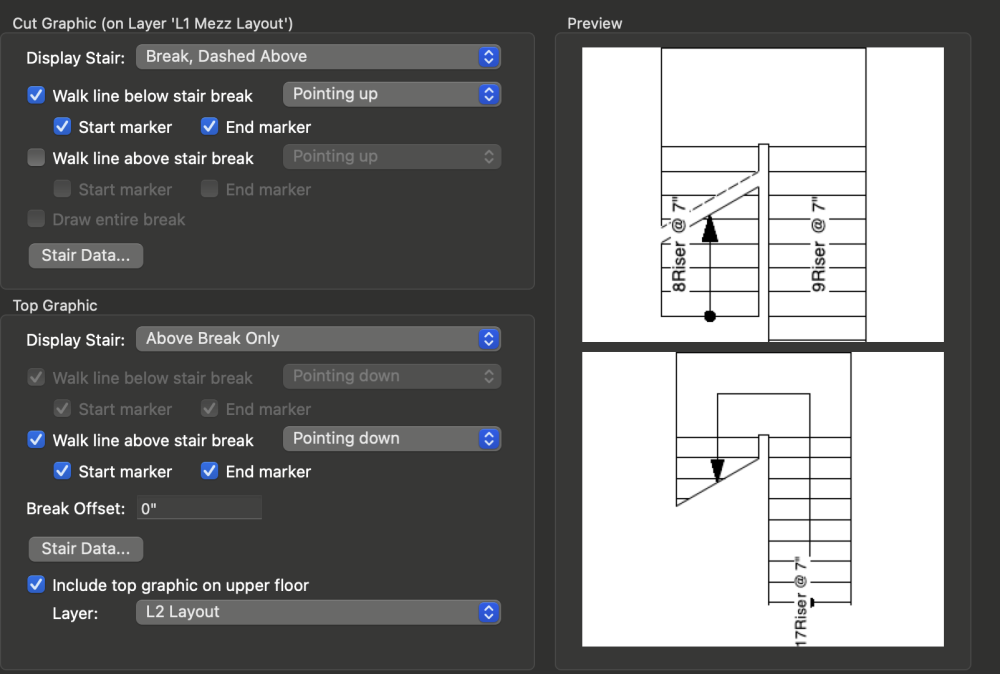
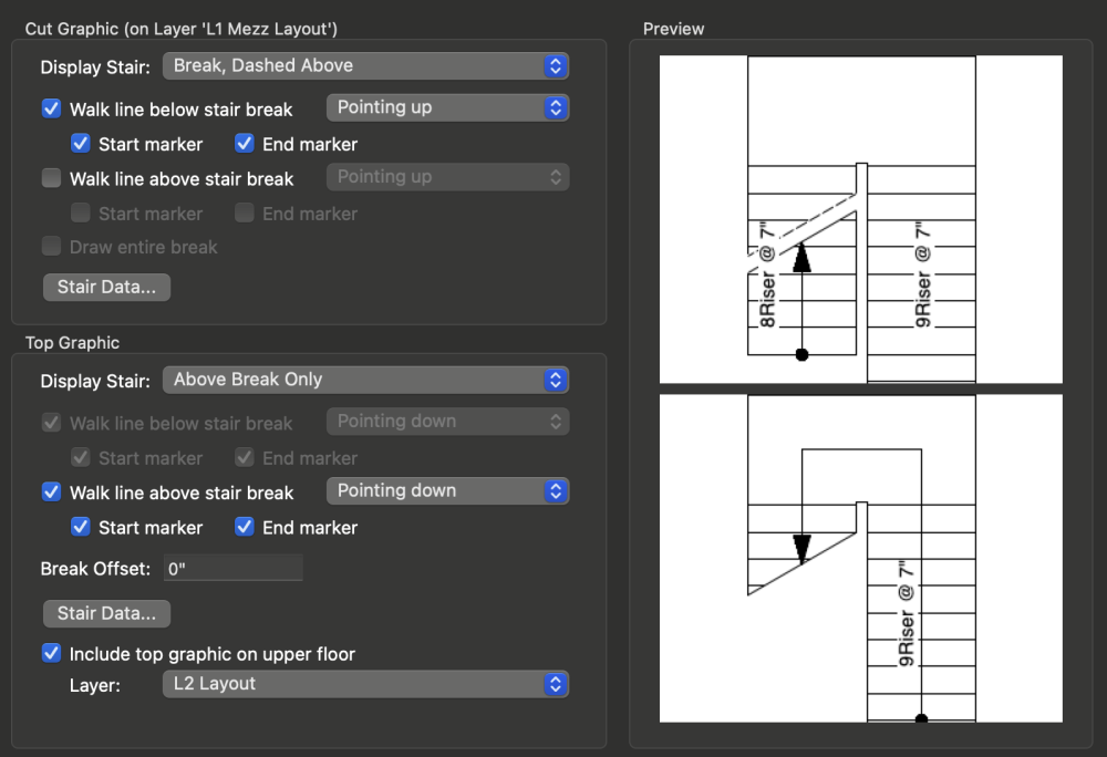
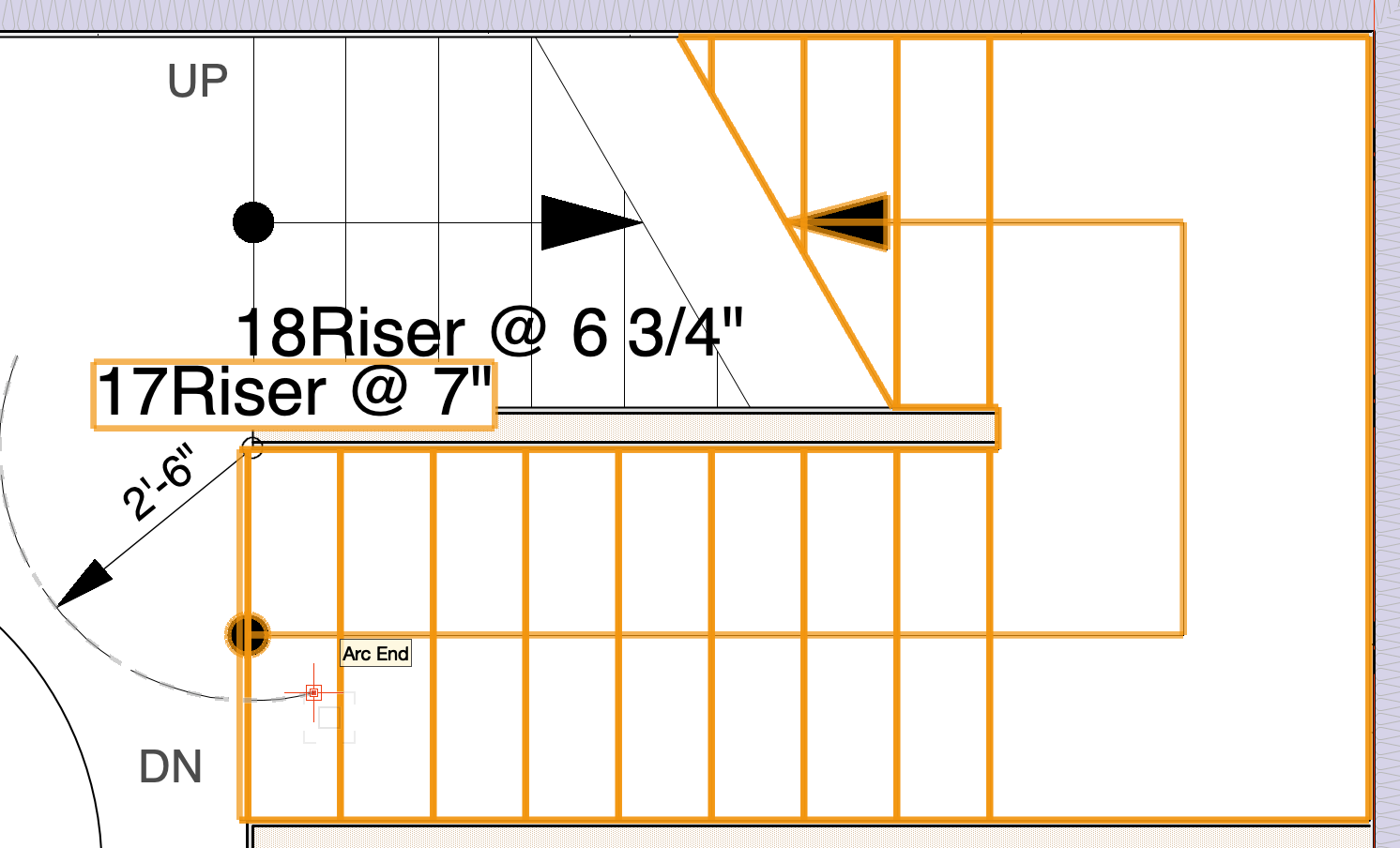
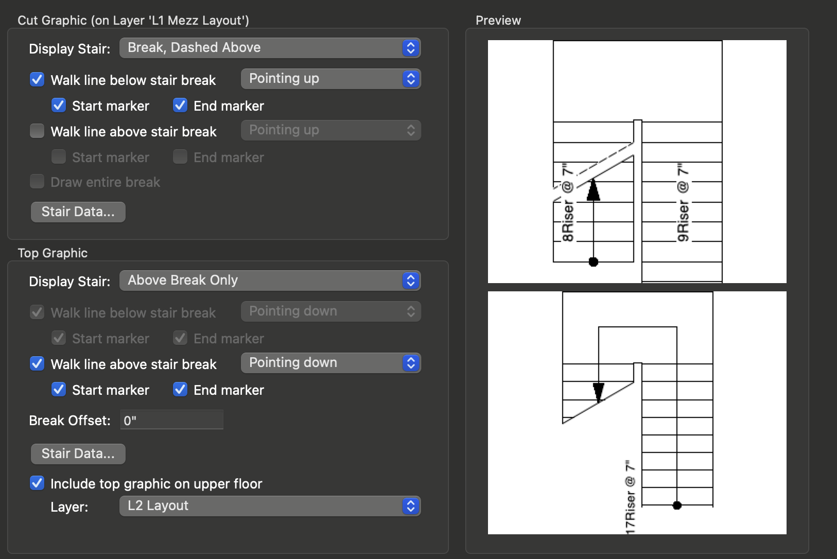
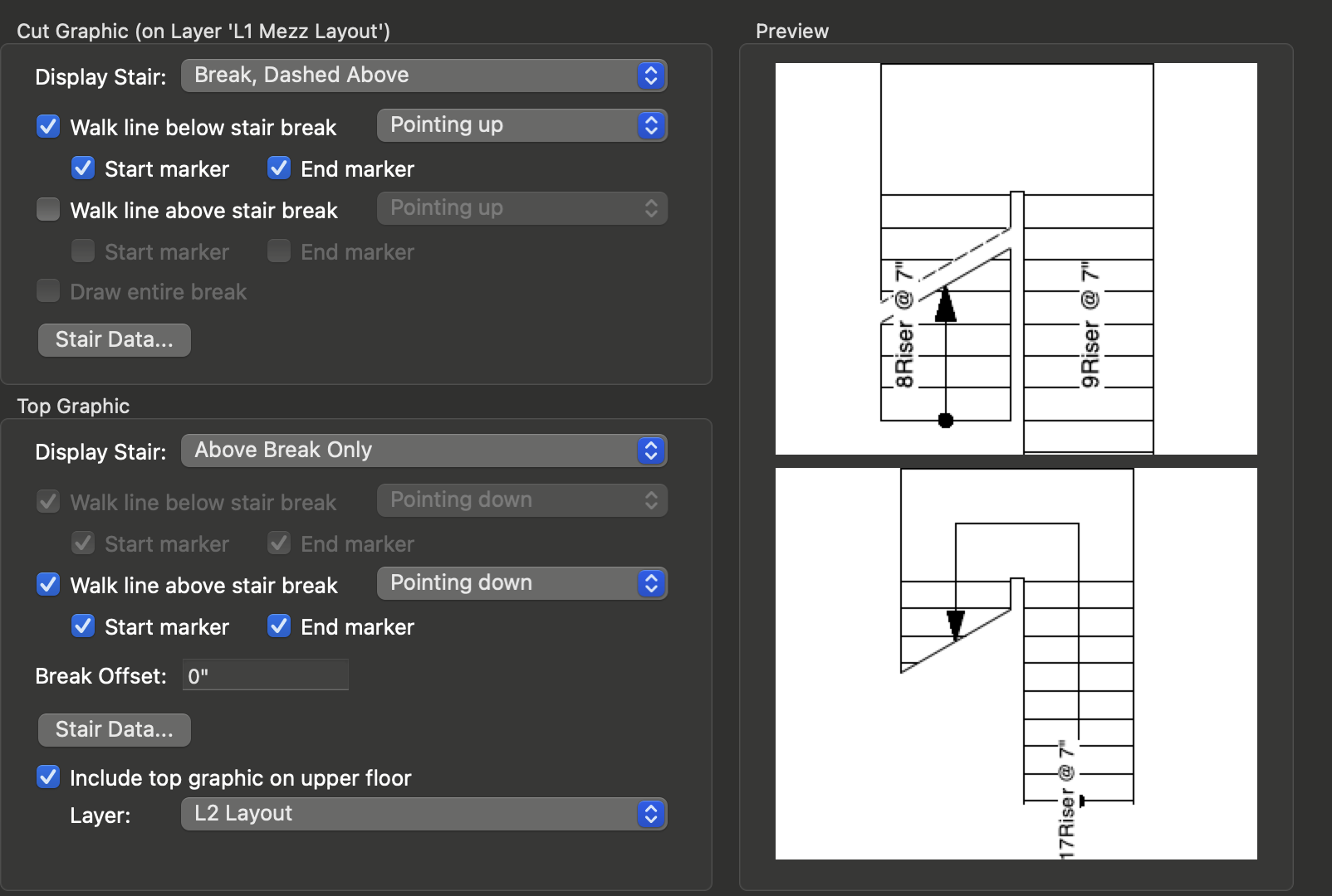
The stair objects does not show the control points to move the stair data when it is activated on the "top graphics".
The bottom or "cut graphic" shows the control point to allow repositioning of the stair data just fine.
Selecting the different note options on the "top graphic" will show the stair data randomly but offers no way to adjust the position.

-
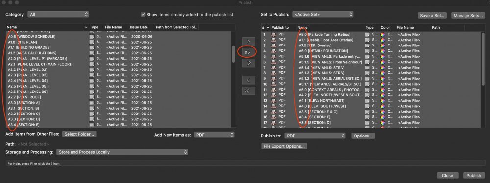
Same issue is happening with us.
Publishing most recent issues will reverse the order.
This is on macOS Catalina, and Vectorworks 2021 SP3.1
-
On 3/10/2015 at 4:25 PM, Matt Panzer said:
Sheet layer viewports can also be grouped, then scaled by dragging a corner grip. Since viewports must be scale proportionally, I usually hold the shift key to constrain the proportions. This will give you a proportional interactive preview as you drag.
This doesn't seem to work with VW 2021 anymore.
The viewport when scaled in group becomes blank.
-
Reference marker in Vectorworks 2021;
Add the functionality for reference markers to link viewports from other Vectorworks files (similar to how the publish function works with multi-file publishes)?
Primary use:
- Allow plan/section/elevation files to link to separate details file.
-
Regarding the new reference marker in Vectorworks 2021;
Is there a way to link viewports to another Vectorworks files (similar to how the publish function works with multi-file publishes)?
This is mainly because our office works with a separate details vectorworks file from the primary plan/elevation/section file.
It would be ideal if we can link the reference markers on the plan/elevation/section file to the actual details on the details file.
-
2
-
-
Hi,
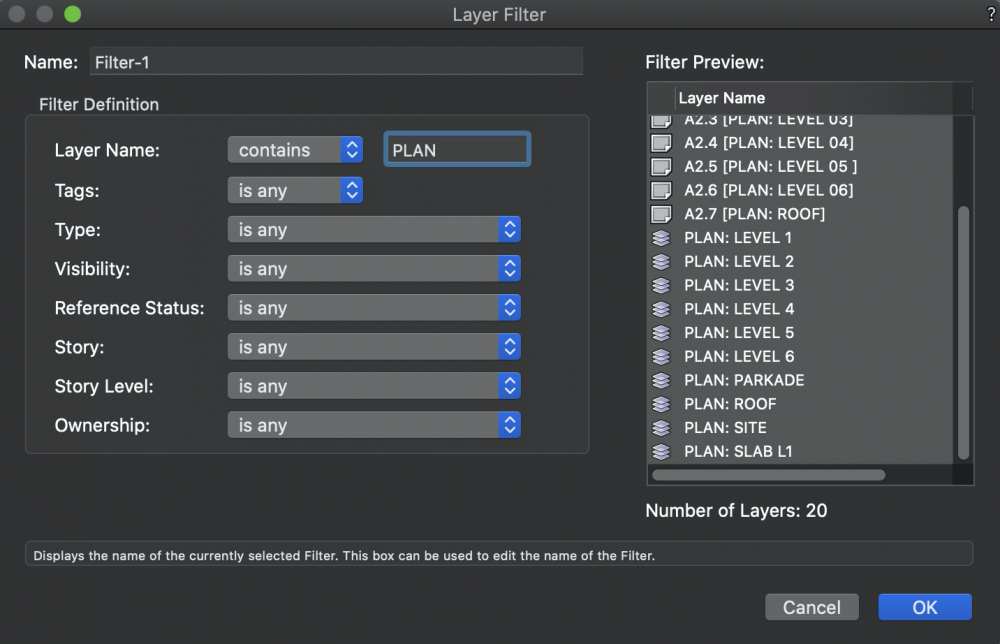
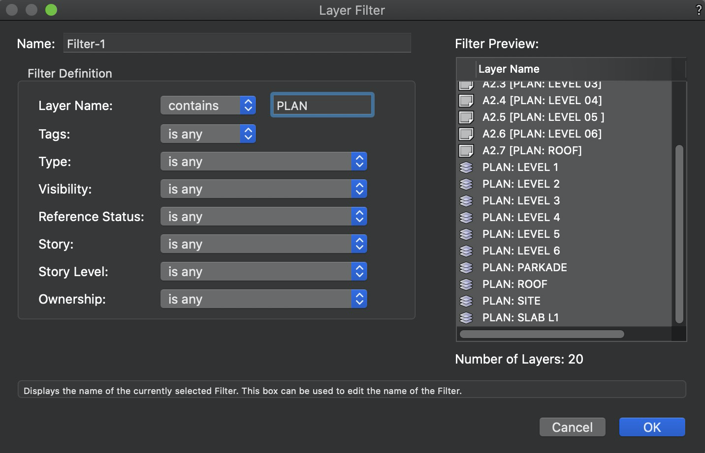
Is there a way to create a filter definition that contains multiple layer names?
For example, if I want to filter out layers that are plans, sections, and elevation, I can add multiple criterias similar to how custom selection is done.
Currently, the layer filter only allows one entry of each definition, so I can only create a filter that separate out plans, or sections, but not both at the same time.
The current work around is to add 1 tag (eg. PSE) to all three types of layers and filter that tag separately.
But this is not ideal since sometimes you want just plans and elevations or plans and sections. Then you need tags for those combinations as well.
-
It looks like we may have found the issue.
The problem occurs on the elevation design layer.
On this layer, there are 24 viewports referencing back to the main floorplans (with lots of symbols and multiple layers turned on).
Moving these viewports onto another design layer and turning it off when drawing on the elevation layer solves the slowdown issue.


Importing ECWs with world files
in General Discussion
Posted
This doesn't seem to work for Vectorworks 2023 and 2024 now.
When importing the ECW file, even with the all-files option selected, it gives an error.