


RedBassett
-
Posts
15 -
Joined
-
Last visited
Content Type
Profiles
Forums
Events
Articles
Marionette
Store
Posts posted by RedBassett
-
-
1 minute ago, Sam Jones said:
I can't help you with the problem of displaying "extra" or formatting the text, but...
You should be able to type in the value of the vertical runs into the vertical distance parameter of any part so that your amounts are correct.
Thank you for the recommendation. I do need to play with the parts feature some more, however my primary concern is the inability to hide the labels. The show calls for some complex cable runs that aren't possible to draw to scale in the paperwork, however if I calculate the needed length for these complex parts, this feature may help! I'll take a look into drawing to scale this time around, and see if I can at least make the lengths line up with the real-world runs better so the extra amount is more realistic, if still impossible to hide.
-
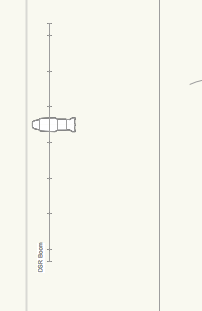
I'm bumping this thread up because I just opened the same show file in VW 2018, and I'm disappointed to see that this is still not an option. Is there a process to officially request this as a feature for future updates? I already have little need for the "extra" amount to be shown (my electricians know the space and know how much extra to expect, it simply clutters the plot), and especially since I am drawing out-of-scale with the rest of the plot (because the cable tool doesn't take 3D model shape into account, so a "50ft" run may actually be 50ft horizontal and a 25ft drop at the end that isn't show in my plot) the amounts I get are completely wrong.
-
Thanks! I would love to see this (and maybe the ability to reformat the length text)!
-
Is there a way to hide the "(XX' Extra)" part of a cable label in Spotlight? I'm drawing cables not-to-scale, and manually setting cable lengths. I'd like to display these specified lengths normally, but without the extra label.
-
16 hours ago, markdd said:
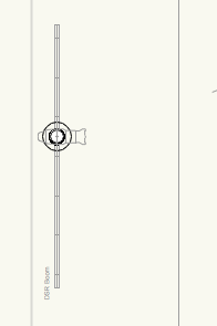
The viewports that are made by running the CPMV command will not show 2D as they have been rotated about the Y axis or if you like, "stood up" as booms. That is because the lighting pipe and instrument objects are 2D/3D hybrid objects which behave in this way on purpose. So what I can see is correct. What I can see is a Source 4 clamped to a vertical pipe which is what is drawn. If you want it to look more like a boom with fixtures hanging from a side arm and the fixture suspended vertically, then you will need to add a side arm and change the instrument 3D orientation in the object info palette.
What is laborious about the CPMV process is that you have to control 3D visibility by turning off and on layers.
The behaviour you showed in the video I am not really sure about, but if you post the original or a demo file here I could take a look.
Hope that is useful.
EDIT: I have uploaded a file showing the way I use this command.
Mark
I'm not saying that the models being displayed in top view is incorrect, just explaining why the layer is off in the screenshot of my layers.
As per the issue of the 3D rendering in 2D viewports, I do not see this behaviour in the sample file you uploaded.
-
22 hours ago, Taproot said:
It may be that the container class is "none", but the objects making up the symbol are probably in another class that is hidden in your viewports. Try editing the symbol and see what classes the objects are on - then turn those classes on in your viewport visibility.
Yup, it was classes used inside the symbol causing the issue. Thanks!
22 hours ago, corbinhand said:Also check the "Dimension" class. I've run into this issue with several of the Elation symbols. Id suggest editing the classes within each of the symbols you use most frequently.
While this class was already on, this is a good check as well. Thanks!
-
5 minutes ago, JBenghiat said:
Have you checked your class visibilities in your viewports? Those symbols can be in a class that is hidden.
-Josh
The 15R symbols and scroller symbols are in the same class (None) and layer as the source four symbols that render correctly.
-
On 11/14/2016 at 3:57 PM, markdd said:
Yes it seems odd.
What I noticed from your layer list is that you have the model layer turned off. It should be turned ON. When you run the CPMV command it creates 2 viewports. One on the layer where the originals used to be and one on the specified model layer. It also changes the original objects to the definition layer. Most of the time you need to delete the first viewport and use the viewport that has been created on the model layer. That viewport is the one that needs to the rotated or "stood up". You will also need to change the 3d hanging orientation of the fixtures that are now on the definition layer if they are going to look right as well - its all quite a process.
There is a video on VW youtube channel that that is reasonably succinct. Let me know if anything I have said here helps at all!
Mark
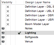
I have that layer off because the 3D models are rendered in plot view, which I don't want. I already have boom symbols in the plot, I turn on that layer when I want to visualize them in 3D, but off to keep the plot clean:
Even with this layer on, the viewports still pop to 3D while in the plot view.
-
I have inserted some Elation Platinum Spot 15R Pros into my lighting plot. They render just fine on the plot and in 3D, however when I switch a sheet layer with a viewport of the plot, they do not show. In fact, colour scrollers and other accessories aren't showing either in viewports. The symbol is being recognized, as I can hover over a dotted circular outline where it should be, but nothing is showing:
What might be causing this?
-
-
Just now, markdd said:
Can you post a picture or better still the file? I have found that the create plot model view works well but takes considerable practice to get right.
mark
My layers:
By default, the viewports render the boom correctly:
However if I hold down [Space] and pan, they suddenly snap to 3D (plus plan view):
If I change the visibility of ANY layer in that layer list (except the selected one: lighting), the 3D goes away and it snaps back to plan view. I will try to capture a video of this behaviour if I can.
-
ADDED: Scroll down to see a video of this issue in action
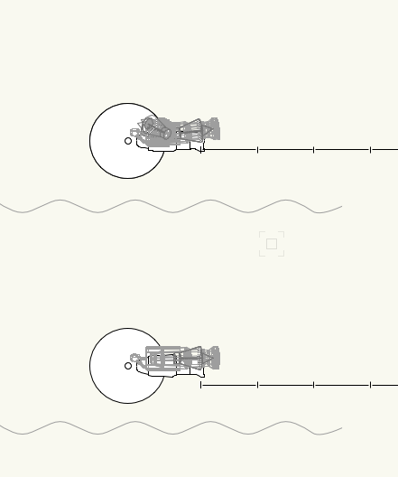
I have a number of booms in my plot. These are shown on my lighting plot layer with viewports created by the Create Plot and Model Views tool. I have the definition and model layers for all of the booms hidden. This setup correctly shows the boom in plan view with instrument symbols. When I pan around the document however (holding down [Space] and dragging with the mouse), the viewports boom viewports all suddenly show the 3D model of their respective booms, including the full width of the pipe and the 3D mesh for the instrument model. If I change the visibility of any non-active layer, the viewports pop back to the (correct) plan view, even if the layer whose visibility I changed has nothing to do with booms (such as my softgoods layer). Toggling the active layer's visibility does not fix the rendering. I assume that this is a bug of some form? If not, what am I doing to cause this behaviour?
Edit:
I can cause a similar behaviour as well: If I edit the definition layer for one of the booms, then hit the Previous View button to go back, all my default layers get shown (such as lighting, softgoods, venue, notes), however only the selected layer (lighting) is shown on screen. If I toggle the visibility of any other layer, all of the missing layers snap back into being shown.
-
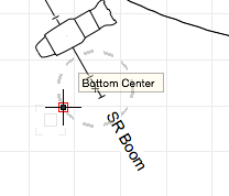
Make sure you have the second mode of the Set Working Plane too selected.
The face should hilight in blue and once you click the Working Plane will be set to that face with the origin at the point you clicked.
By second mode you mean Planar Face Mode? Yes, I do. The blue highlight works as I hover around, but after clicking, nothing changes and no working plane appears.
Edit: Missed the attachments. Yes. I am using planar face mode and clicking the face I want to select.
Edit 2: You've magically fixed it. I opened the file to get a screenshot, repeated the same steps I did over-and-over yesterday, and it worked.
-
First in what will probably be a long line of issues!
I am trying to use the working plane tool. I select the tool and set it to the Planar Face Mode. I hover over the face I want to use. I click and the tool blinks. Great so far. Problem is, that the working plane doesn't get set. As far as I can see visually, aside from that blink when I click, nothing changes. I couldn't find how to deactivate automatic plane, but I found the backslash shortcut for it, and the message bar says it isn't available in this context (so I assume that isn't stopping me). Any idea how to actually set the working plane?
Thanks!
Hide Cable Extra Label
in Entertainment
Posted
I've poked around those display options a bunch already, but unfortunately the extra length label is part of the length display, which I do want. Thanks though!