


Paolo
-
Posts
181 -
Joined
-
Last visited
Content Type
Profiles
Forums
Events
Articles
Marionette
Store
Posts posted by Paolo
-
-
-
The menu command Export to SVG is officially released.
Available on the Gumroad® platform at €25+ or starting from the product page: https://fitplot.it/vwplugins/exportSVG.html
The plugin is available for both Vectorworks®2020 and 2021.
Beta versions (on the website) remain available until expiring (December 15th 2020).
On request I can provide evaluation version (working for a limited time).
Please send requests / comments / feedback through the form (bottom of the page on the website).
-
 1
1
-
-
A beta version of my Export to SVG menu command is now available for a limited time...
-
A beta version of my Export to SVG menu command is now available for a limited time...
-
Export to SVG is a menu command (available for Vectorworks® 2020 and 2021)
Available in beta version (expiring December 15th 2020)
Downloadable from here...
Please, let me have your feedback / suggestions
The final plugin will be available at a fair price on my Gumroad® page and on my website.
-
I do not know what is causing this error.
I suspect this is due to the encryption I have done.
Another cause may be that the plugin has been made and encrypted in VW2021 and though there is no use of newer functions (that were not present in VW2020), the encryption phase may have been changed.
A third cause may be due to the new python 3.7 provided with VW2021.
Tomorrow I should be able to prepare e VW2020 version and submit it to all for testing.
-
@Brian(J) try to download the file again, let me know if the error persists.
-
here's the instructions (from the site)...
Unpacking the downloaded zip file, you'll find a sole element:
Export to SVG.vsm
- Move the “Export to SVG.vsm” file inside your Vectorworks Plug-ins folder (in your case C:\Program Files\Vectorworks 2020\Plug-Ins).
- Restart Vectorworks.
- Edit your workspace adding the menu Export to SVG command (you'll find it in Import/Export category)
- Usually you'll add it in the File menu, Export submenu.
- Save the workspace.
- In the end you should get a new menu item Export to SVG in the File -> Export submenu.
Here instructions for editing the workspaces:
https://app-help.vectorworks.net/2020/eng/VW2020_Guide/Start/Customizing_workspaces.htm
And here instructions to add a menu command:
Note: the plugin is written in VW2021, however your 2020 should get it to work.
-
Here's the Export to SVG beta to test:
The Beta shows a dialog at start that will be removed in the final release.
The Beta will cease to work on December 15th, I hope to get some feedback, here on this post or with the form on the plugin page
-
@Brian(J) I am preparing a Beta version for you (and all) to download and try.
I will post the download link asap.
P.S.:
the SVG code in my files has not changed since earlier versions. Usually SVG readers are very tolerant. I am the author of the SVG import plugin that is included in the Vectorworks italian version and I can assure you that there are, out there, so many ways of how the svg are listing their numerical values (with or without commas, spaces, carriage returns etc.) and it seems to me strange that Shaper cannot read a simple SVG 1.1 file that passes the official Mozilla consortium validation.
I have seen that the SVG exported with the Fusion plugin adds specific code that Shaper uses, but this should be obtained also interpreting the colors and fills suggested in their templates.
-
@Brian(J) this is my attempt:
Substantially, I have copied the header:
<?xml version="1.0" encoding="utf-8"?>

<!-- Generator: SVG Export Plug-In © Paolo Marcuccetti 2020. SVG Version: 20201206  -->

<!DOCTYPE svg PUBLIC "-//W3C//DTD SVG 1.1//EN" "http://www.w3.org/Graphics/SVG/1.1/DTD/svg11.dtd">
<svg version="1.1" id="Level_1"
x="0px" y="0px" width="558.96px" height="782.8799999999999px"
enable-background="new 0 0 558.96 782.8799999999999"
viewBox="0 0 558.96 782.8799999999999"
xml:space="preserve"
xmlns="http://www.w3.org/2000/svg"
xmlns:shaper="http://www.shapertools.com/namespaces/shaper"
xmlns:xlink="http://www.w3.org/1999/xlink">
and inserted a "," comma between x and y coordinates of the various path vertexes (as seen in your examples).
I hope this work.
Since I do not know what are Shaper SVG specific rules, I cannot go further chasing a (particular) solution by attempts, with the risk of losing the general compatibility.
-
@Brian(J) my linked SVG files are actually hosted on my website.
To send me an SVG, simply compress it as zip, then you can attach it to a post in this forum (as the .zip I sent you before).
-
New SVG test updated produced with the latest plugin version.
Feel free to test it in your workflow, I'd like to have your feedback.
-
Hi @Brian(J),
here I am
I have refurbished my algorithm to avoid the usage of the <g> tag so you do not have to ungroup.
The produced SVG is 1.1 to maximise the compatibility.
Hope this works.
-
Thank you @Brian(J) for your prompt reply.
Here's a file with just three rows of converted text
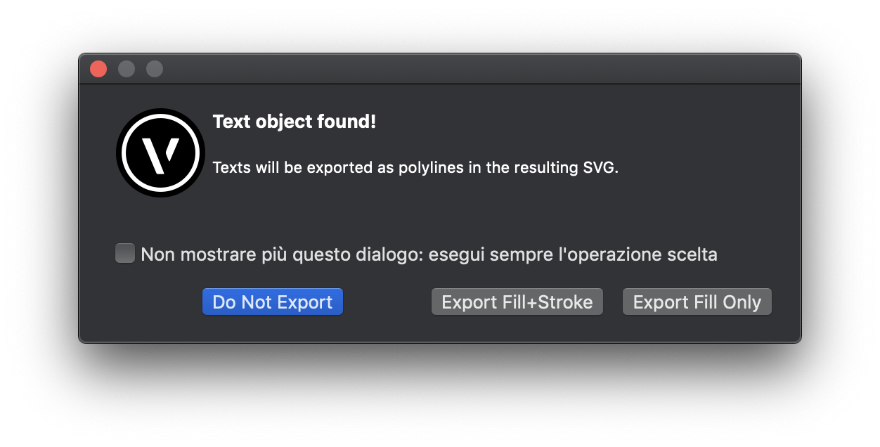
When the program finds a "text" type in the selection, it shows this dialog:
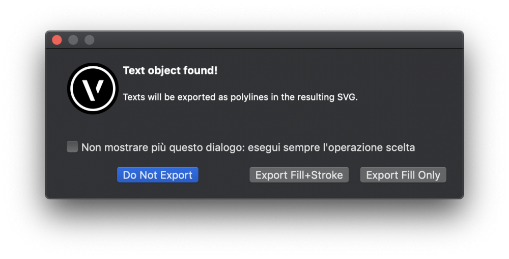
If you include strokes, they will be 1pt with the same color as fill.
Thank you to get in touch with Shaper.
I have browsed their site and downloaded their Illustrator template to compare with mine.
No differences (they use SVG 1.1 as in my previous tests), rather my code is more simple and clean, since I want it to be widely compatible.
Hope they give some tracks, though.
-
Thank you @Brian(J) for your test.
Objects come grouped, this is necessary due to the transformation (scale(1,-1)) needed to flip the Y axis that is reversed in Vectorworks.
This is needed, there is no other way to flip Y, as far as I know.
About the truncated circle, this is a very special case where you cannot get the same (partially stroke in Vectorworks) circle in SVG unless you draw a truncated circle (really is a polyline) for the fill and an arc for the stroke.
About the letters, they should be polylines, maybe the problem is that they have no stroke and your program does not recognise it?
This should not a be a problem.
From a graphical point it is correct that there is no stroke (as they appear in Vectorworks!) but if you need strokes, anyway, I'll do in way to propose stroke as option.
I have also changed the SVG version
<svg xmlns="http://www.w3.org/2000/svg" version="1.2" baseProfile="tiny"since I use the attribute
vector-effect="non-scaling-stroke"that is available from this version (1.2 Tiny).
However this attribute is already present in most SVG implementations, but it may be not the case of Shaper, that does not recognise the code.
I have tried with an online validator this new version and it passes the test correctly.This attribute is used to get the the visually balanced line weight independently from view zoom, but it does not alter the real weight (that is, if you open the exported file in Illustrator, you get the same line weight that in Vectorworks), so I can simply decide to omit this attribute, if it 'd be a problem.
I have uploaded the updated version of the two tests, please, give them a try, if you can.
-
Here's a couple of SVG produced with the Export selection to SVG command.
Feel free to test it in your workflow, I'd like to have your feedback before to release.
and here's a part of the produced SVG code:
geometry text.svg
<?xml version="1.0" encoding="utf-8"?>

<!-- Generator: SVG Export Plug-In © Paolo Marcuccetti 2020. SVG Version: 20201128)  -->

<!DOCTYPE svg PUBLIC "-//W3C//DTD SVG 1.1//EN" "http://www.w3.org/Graphics/SVG/1.1/DTD/svg11.dtd">
<svg version="1.1" id="Level 1" xmlns="http://www.w3.org/2000/svg" xmlns:xlink="http://www.w3.org/1999/xlink"
x="0px" y="0" width="595.2px" height="841.68px"
viewBox="0 0 595.2 841.68"
xml:space="preserve">

<g transform="scale(28.346456692913385 -28.346456692913385)
translate(10.498666666666667 -14.8463)">
<rect x="-8.498666666666667" y="7.995558273480356" width="4.850741726519645" height="4.850741726519644"  fill="rgb(204, 204, 204)"  vector-effect="non-scaling-stroke" stroke-linecap="round" stroke-width="2.016"  stroke="rgb(221, 9, 7)" />
<rect x="-2.425370863259822" y="7.995558273480356" width="4.850741726519645" height="4.850741726519644" rx="1.0" ry="1.0"  fill="rgb(204, 204, 204)"  vector-effect="non-scaling-stroke" stroke-linecap="round" stroke-width="2.016"  stroke="rgb(221, 9, 7)" />
<path  fill="rgb(204, 204, 204)"  vector-effect="non-scaling-stroke" stroke-linecap="round" stroke-width="2.016"  stroke="rgb(221, 9, 7)"  d=
"M8.498666666666667 11.425550642086936  7.077917308753603 12.8463  5.068674298060086 12.8463  3.6479249401470226 11.425550642086938  3.6479249401470226 9.416307631393419  5.068674298060084 7.995558273480356  7.077917308753605 7.995558273480356  8.498666666666665 9.416307631393417  Z
"/>
<circle cx="-5.924629136740178" cy="3.570187410220533" r="2.4253708632598228"  fill="rgb(204, 204, 204)"  vector-effect="non-scaling-stroke" stroke-linecap="round" stroke-width="2.016"  stroke="rgb(221, 9, 7)" />
<path  fill="rgb(204, 204, 204)"  vector-effect="non-scaling-stroke" stroke-linecap="round" stroke-width="2.016"  stroke="rgb(221, 9, 7)"  d=
"M2.4253708632598228 2.746332281802734  -0.6412188019392882 2.746332281802734  -0.6412188019392879 4.394042538638335  2.4253708632598228 4.394042538638335  2.4253708632598228 5.995558273480356  -2.425370863259822 5.995558273480356  -2.4253708632598214 1.1448165469607112  2.4253708632598228 1.144816546960712  Z
"/>
<path  fill="rgb(204, 204, 204)"  vector-effect="non-scaling-stroke" stroke-linecap="round" stroke-width="2.016"  stroke="rgb(221, 9, 7)"  fill-rule="evenodd" d=
"M5.078295803406844 2.5751874102205337  5.078295803406844 4.565187410220534  7.068295803406845 4.565187410220534  7.068295803406845 2.5751874102205337  Z
M8.498666666666665 3.5701874102205333
A2.425370863259822 2.425370863259822 10313.240312354817 0 1 3.6479249401470213 3.5701874102205347
L3.6479249401470213 3.5701874102205333
A2.425370863259822 2.425370863259822 10313.240312354817 0 1 8.498666666666665 3.5701874102205324
 Z
"/>
<line x1="-8.498666666666669" y1="-12.206080187949256" x2="8.498666666666669" y2="-12.206080187949256"  vector-effect="non-scaling-stroke" stroke-linecap="round" stroke-width="1.2959999999999998"  stroke="rgb(119, 119, 119)" />
<line x1="-8.498666666666669" y1="-12.8463" x2="8.498666666666669" y2="-12.8463"  vector-effect="non-scaling-stroke" stroke-linecap="round" stroke-width="1.44"  stroke="rgb(119, 119, 119)" />
</g>
</svg>
-
The plugin is now in an advanced testing phase (it is ready, almost).
I just want it to be perfect, more or less 😉
Please follow this post to know the release announce.
As promised in my previous reply, I have added the support for texts.
Texts that are included in the selection to export, are sent to the SVG as paths.
No need for the user to convert them into polylines. All is done inside the plugin process.
-
 1
1
-
-
@Brian(J), I know, of course, just forgotten to mention it in the post (edited!)
Convert a text to path and you get a polyline (or a group of polylines).
Ungroup, if needed, and you are ready to export in SVG.
This is just the first version. I will add the text support either as direct text tag in the SVG or advising the user about the conversion to path (copying and converting it on the fly, leaving the actual text untouched).
-
Good news!
-
1
-
-
Hello, I am happy to show you my next coming plugin (menu command) to export SVG out of Vectorworks.
Here's a short presentation with a video:
-
Hello, I am happy to show you my next coming plugin (menu command) to export SVG out of Vectorworks.
Here's a short presentation with a video:
-
Hello,
my new plugin to get SVG files out of Vectorworks is in beta testing.
Let me know if you are interested, as soon as I am ready the plugin will be placed on my Gumroad® page, at a reasonable price.
With this menu command you'll be able to export your Vectorworks elements (such as polylines, polygons, rects, arcs etc.) objects to an SVG file suitable for CNC machines.
All you have to do is select the objects to export and select the menu "Export selection to SVG", then choose a file name and click OK.
The program will produce the correct SVG code to replicate the same selected object in the SVG viewbox determined by the Vectorworks active layer drawing size.
Object are exported relatively to the active layer scale, so, if you need them for CNC purposes, better set the layer scale to 1:1 before exporting.
What Export selection to SVG can do:
The plugin CAN export the following Vectorworks objects:- Lines
- Rects
- Rounded rects
- Arcs / circles
- Ellipses
- Polygons
- Polylines (also with holes)
The plugin CANNOT export all the other types that are not included in the above types such as:
- Groups, Symbols, Plugin objects (unless converted in the above types)
- 3D objects
- Texts (unless converted to polylines)
- Quotes
- Images
Attributes:
The SVG produced will preserve the following object attributes:- Solid fills
- Solid strokes
- Fill and stroke colors
The plugin does not consider dashes, gradients, textures etc..
-
1
-
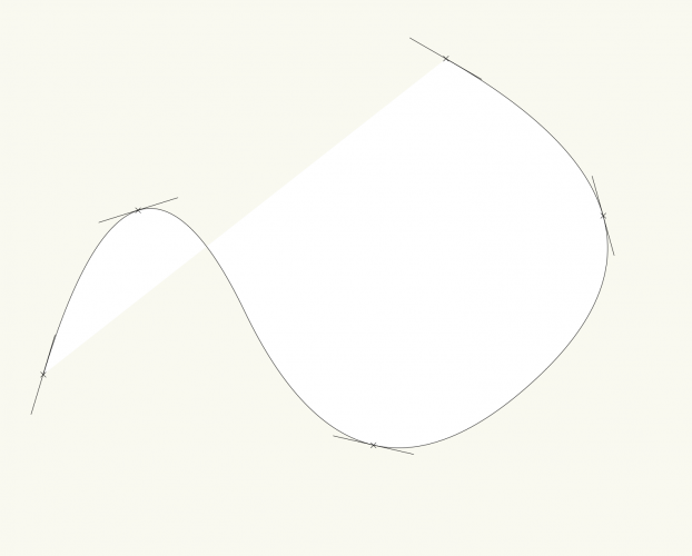
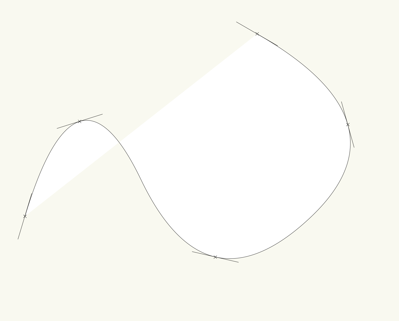
I have found a way, it works, but has some inaccuracy (due to the PointAlongPoly precision), but I can leave with it.
Of course, if there is a better solution it will welcome!
import math

def angleBetweenPoints(p1, p2):
#given 2 point coordinates it retrieves the angle of the line passing between them
	orientation = None

	if p1[0]==p2[0]:
		if p1[1] <= p2[1]:
			orientation = 90
		else:
			orientation = 270

	if p1[1]==p2[1]:
		if p1[0] <= p2[0]:
			orientation =  0
		else:
			orientation = 180

	if (p1[0]!=p2[0]) and (p1[1]!=p2[1]):
		if p1[0]<p2[0]:
			quadrant = 0
		else:
			quadrant = 180
		orientation = quadrant+vs.Rad2Deg(vs.ArcTan((p1[1]-p2[1])/(p1[0]-p2[0])))
	return orientation

def tangentAtIndex(h, index, resolution):
	minDist = 1e308 #a very large number initially
	tangent = None

	ptVt, vertexType, arcRadius = vs.GetPolylineVertex(h, index)

	ht = vs.ConvertToPolygon(h, resolution)
	#cycle searching min distance
	for i in range(1, vs.GetVertNum(ht)+1):
		pi = vs.GetPolyPt(ht, i)
		dist = vs.Distance(ptVt[0], ptVt[1], pi[0], pi[1])
		if dist < minDist:
			minDist = dist
			if (i > 1) and (i+1 < vs.GetVertNum(ht)):
				pt1 = vs.GetPolyPt(ht, i-1)
				pt3 = vs.GetPolyPt(ht, i+1)
				c = vs.ThreePtCenter(pt1, pi, pt3)
				tangent = angleBetweenPoints(c, pi)+90
			else:
				if i == 1:
					#angle between 1 and 2
					pt1 = vs.GetPolyPt(ht, 1)
					pt2 = vs.GetPolyPt(ht, 2)
					tangent = angleBetweenPoints(pt1, pt2)
				if i == vs.GetVertNum(ht):
					#angle between latest and latest-1
					pt1 = vs.GetPolyPt(ht, vs.GetVertNum(ht))
					pt2 = vs.GetPolyPt(ht, vs.GetVertNum(ht)-1)
					tangent = angleBetweenPoints(pt1, pt2)

	vs.DelObject(ht)
	return tangent


#test a selected polyline

h = vs.FSActLayer()

for i in range(1, vs.GetVertNum(h)+1):

	t = tangentAtIndex(h, i, 512)
	p, vertexType, arcRadius = vs.GetPolylineVertex(h, i)
	vs.Locus(p[0], p[1])
	vs.MoveTo(p[0]-1*math.cos(vs.Deg2Rad(t)), p[1]-1*math.sin(vs.Deg2Rad(t)))
	vs.LineTo(p[0]+1*math.cos(vs.Deg2Rad(t)), p[1]+1*math.sin(vs.Deg2Rad(t)))

svg export
in Wishlist - Feature and Content Requests
Posted