
Bruce Kieffer
-
Posts
2,816 -
Joined
-
Last visited
Content Type
Profiles
Forums
Events
Articles
Marionette
Store
Everything posted by Bruce Kieffer
-

Subtracting Object Disappears when the Subtraction is Ungrouped?
Bruce Kieffer replied to Bruce Kieffer's question in Troubleshooting
I can't reproduce it now since I fixed the problems and moved on. But what you are saying makes me wonder if when I made those subtractions originally I may have used a symbol that got replaced at a later time. My files use similar resources, and sometimes I pick a resource from another open file. I've been trying to be more careful about that. -
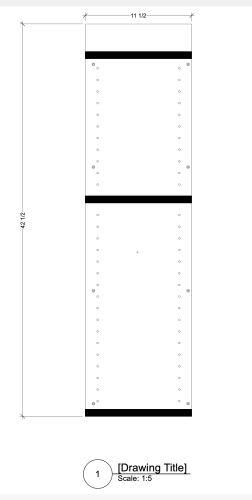
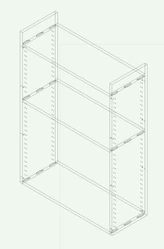
I want to use section viewports to isolate cabinet components to dimension them. Here is a a side of an upper cabinet. Problem is I can't find a section VP wire frame render option. Those black rectangles are cabinet dividers where the VP is cut. I need those to be transparent so I see and dimension the biscuit grooves I need for assembly. Is there some setting I can change to make those black rectangles wireframe? This is how the design layer looks:
-
Subtracting Object Disappears when the Subtraction is Ungrouped?
Bruce Kieffer replied to Bruce Kieffer's question in Troubleshooting
Not that I remember, but that might be a good reason why they are gone. I rebuilt the sides and they are good now. -
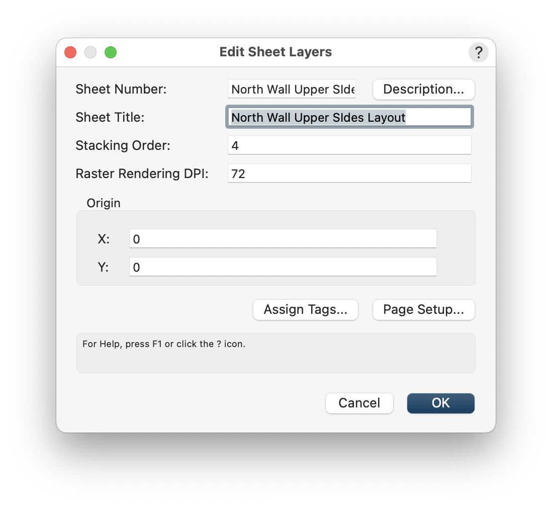
Is there a simple way to display the sheet layer title on a sheet?

-
Subtracting Object Disappears when the Subtraction is Ungrouped?
Bruce Kieffer replied to Bruce Kieffer's question in Troubleshooting
Here's a file with the bad solid subtraction. Ungroup it and see if you can figure out what happened to the counterbores. Bad Solid.vwx -
Subtracting Object Disappears when the Subtraction is Ungrouped?
Bruce Kieffer posted a question in Troubleshooting
I'm using a counterbore symbol to subtract (drill) counterbore holes in a 3/4" thick panel. If I ungroup the subtraction the counterbore symbols disappear. I have turned on all class and all layers and the counterbores are just gone. Why might this be happening?
-
When editing a symbol and turning classes on and off, and then using previous and next view, my screen goes blank. The objects are there, but not visible. Nothing other than exiting the edit mode. Anyone else have this happen? Have you found a workaround?
-
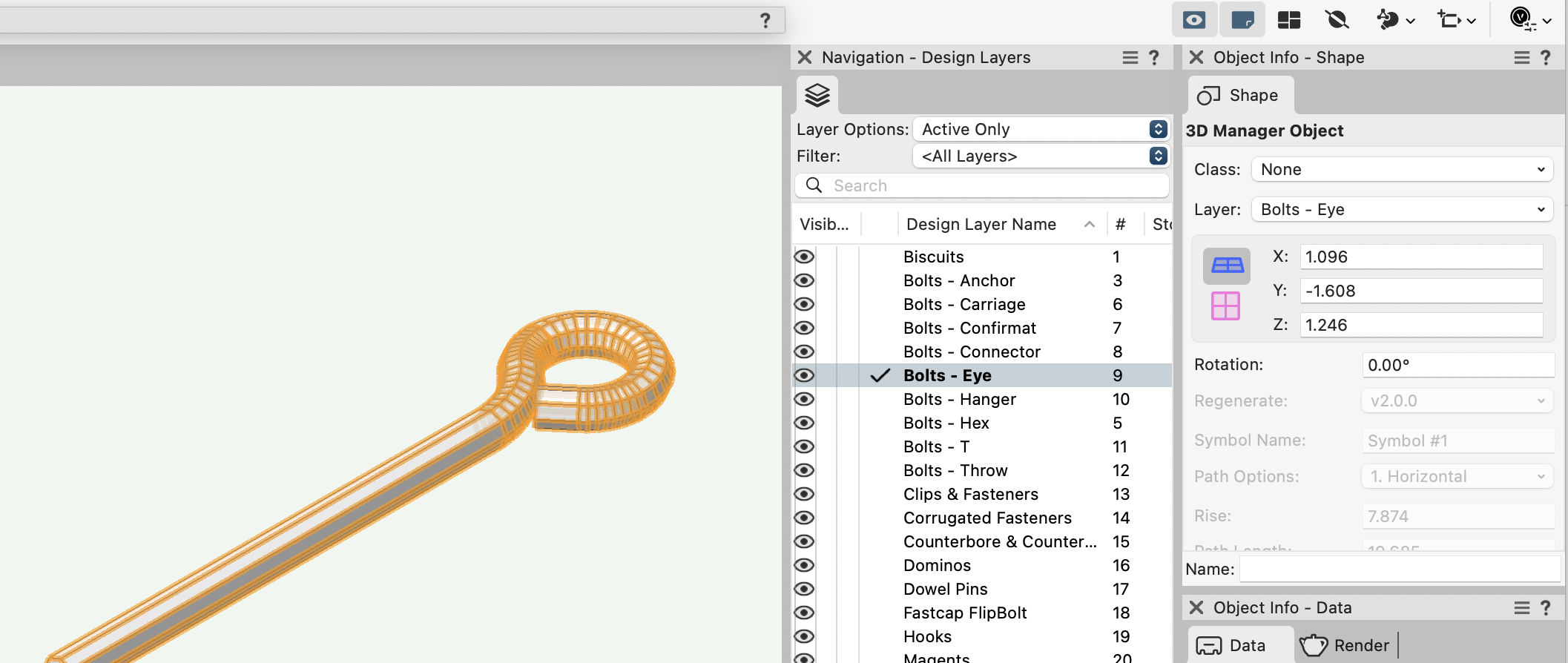
What is a 3D Manager Object? Seems this eye bolt I drew years ago is one. I can't modify it.

-
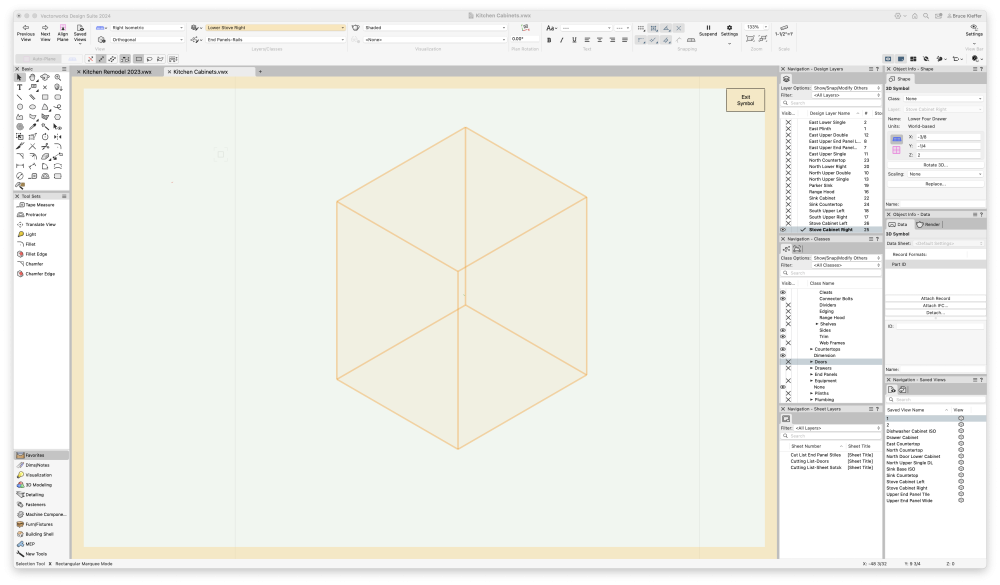
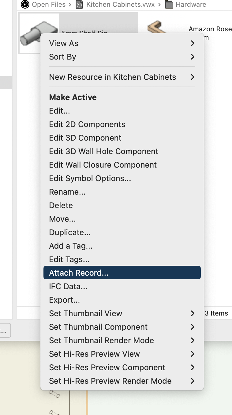
I did some more experimenting with the Attach Record... command. As I said above, it works to attach records to referenced symbols when the command is used in the destination file, but I can't edit the record value in the Attach Record... command, I can edit the value in the worksheet. I can use the Attach Record... command in the RM to symbols in the current drawing and that works, and I can edit the value either in the Attach Record... dialog box or the OIP. I cannot delete a record from a symbol using the Attach Record... command. I wish this worked with referenced symbols.
-
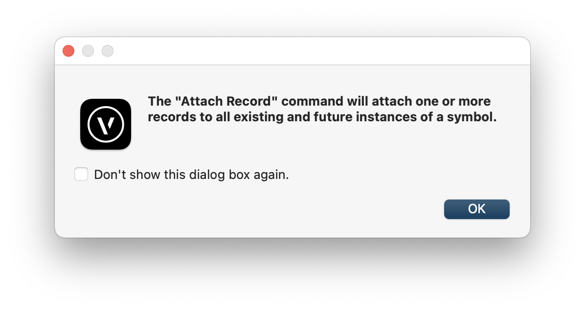
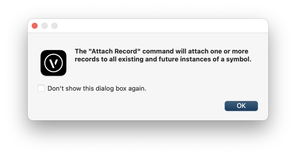
This is what I'm having trouble with. When I use the Attach Record... command to a symbol in the RM I get this dialog box. That's really what I want, but it seems it does not work with referenced symbols. If I go to the RM referenced symbol in the destination file and use the Attach Record... command there, it will attach the record but I cannot edit the value. To edit the value I have to edit that field in the worksheet. I wish this was simpler. I spent hours last night trying to figure out how it works.
-
I completely understand. Thanks @Pat Stanford
-
I'm having trouble making this work. How is it done?
-
All or Any criteria in this set?
Bruce Kieffer replied to Bruce Kieffer's topic in General Discussion
Got it working. For me it's a lot of trial and error. At least I understand what it does now so maybe I can use it to my advantage in the future.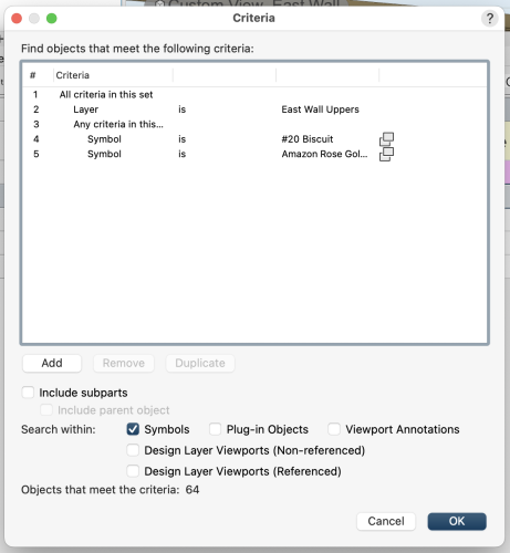
-
All or Any criteria in this set?
Bruce Kieffer replied to Bruce Kieffer's topic in General Discussion
That's exactly what I'm looking to know. Now I need to mess around with it a bit. Thanks @Tom W. -
All or Any criteria in this set?
Bruce Kieffer replied to Bruce Kieffer's topic in General Discussion
But what is the result? What does that do to the entire criteria? -
All or Any criteria in this set?
Bruce Kieffer replied to Bruce Kieffer's topic in General Discussion
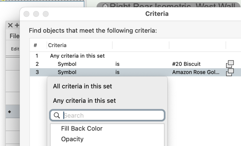
I'm referring to adding the any or all to item #3 How does that work? -
Please explain how this works to select Any or All a criteria item down in the criteria list? I've experimented a bit, and I cannot figure out how it works or what it does.
-
Custom Dimension Standard as resource?
Bruce Kieffer replied to Bruce Kieffer's topic in General Discussion
That's a good idea. I will give it a try. Thanks. -
Is there a way to make a Custom Dimension Standard as a resource? Two workarounds I've use so far are copy/paste the dimension formatted with my custom standard from one drawing to another. That brings the dimension standard to the other file. The other workaround is to draw dimensions in one of my library drawings and apply my custom dimension standards to each and then use that drawing as the source to import my custom dimension standards to another drawing. These workarounds seem counter intuitive to the purpose of the resource manager. I want to save my custom dimension standards in the resource manager. Is there a good way to do that?
-
Save All Command
Bruce Kieffer replied to Bruce Kieffer's question in Wishlist - Feature and Content Requests
That's never been a problem for me. So what this might mean is that the auto-update from the referenced file could be optional in a setting. -
Save All Command
Bruce Kieffer replied to Bruce Kieffer's question in Wishlist - Feature and Content Requests
Absolutely. For a long time now I've been trying to imagine a time when I would not want to updated a referenced file, and I could come up with none. -
I'm not having trouble. I was just curious which format might be best. I'm downloading for the Blum Hardware site. I don't suggest you try there. I have been pulling my hair out for the past day trying to figure out how to get to the CAD files. It's too bad that these companies don't test there sites with users to find out how frustrating it can be.
-
True. I'm downloading CAD files of drawer slides from Blum.
-
I went back to the CAD file download page and tried some of the other file formats. All the results are the same. Everything imports to Vectorworks as a generic solid.
-
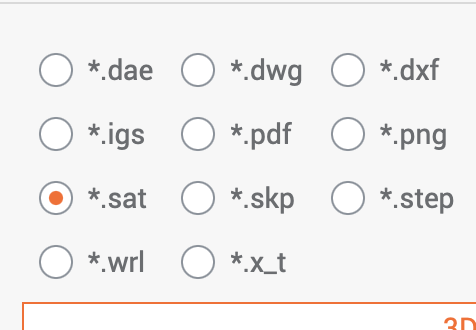
I'm importing a drawer slide CAD drawing. Which of these options might be best for Vectorworks?