


michaelk
-
Posts
6,379 -
Joined
-
Last visited
Content Type
Profiles
Forums
Events
Articles
Marionette
Store
Posts posted by michaelk
-
-
I wonder if this is another Mac OS update issue.
Can you post a file to test?
-
-
When I copy/paste on your file it works correctly!
-
Do any of your database header cells reference other cells?
-
This is what I see when I do that.
-
Are you coping and pasting both rows 1 & 2 together into rows 4 & 5 in one action? (The label didn't advance one column over, but the database headers did)
-
Wow. I do that all the time and I've never see that.
Can you post a file with the offending worksheet?
-
That's a new one!
Are you clicking on the row header to select the row or selecting all the cells?
Are there any merged cells in the worksheet?
-
2 hours ago, SthavyaK said:
The only issue I am facing is when there are bends along the path. I did try dividing the curves to smaller portion but the bricks don't stitch(excuse my laser scan-point cloud language) right. Do you think I can edit this .vso or if you could help me with that? My other option is to do manual work along the curves. What do you suggest?
Yeah, I was afraid of that :-). This plug-in is set up as a rectangular object. It could be set up as a path object, but the vector math gets much more complicated. And at every radius some tiles have to be drawn as non rectangles.
But I think it can be done. I don't have time to do it at the moment. (And I have a bunch of plug-ins I'm making for my own work that are almost done and need some attention)
I'll post the code here if you want to play around with it.
Procedure RandomBricks; {Badly Scripted by Michael Klaers.} {April, 2024 Seattle WA} VAR objHd,recHd,wallHd : HANDLE; tempH1, tempH2 : HANDLE; boolResult, resultStatus : BOOLEAN; RowCounter : INTEGER; RandRectWidth, DrawHereX, DrawHereY, RowOffset : REAL; objName, RecName, FieldName, testClass, RadioButtonResult : STRING; {****************************** Pick A Brick Width *************} PROCEDURE PickABrick; VAR BrickNum,RandoI : INTEGER; RandoR : REAL; BEGIN BrickNum := TRUNC(Str2Num(pNumBrickSizes)); RandoR := Random; RandoI := TRUNC(RandoR*BrickNum)+1; CASE RandoI OF 1 : RandRectWidth := pBrickWidth1; 2 : RandRectWidth := pBrickWidth2; 3 : RandRectWidth := pBrickWidth3; 4 : RandRectWidth := pBrickWidth4; 5 : RandRectWidth := pBrickWidth5; END; {CASE} END; {****************************** Set an X Offset *******************} PROCEDURE OffsetX; BEGIN PickABrick; RowOffset := RandRectWidth/2; END; {****************************** Draw A Brick *******************} PROCEDURE DrawABrick; BEGIN RectangleN( DrawHereX,DrawHereY-pBoxWidth/2, 1,0, RandRectWidth,pBrickHeight); DrawHereX := DrawHereX + (pGroutwidth * 2) + RandRectWidth; END; {***** MAIN *****} {***** MAIN *****} {***** MAIN *****} BEGIN resultStatus := GetCustomObjectInfo(objName,objHd,recHd,wallHd); SetObjectVariableBoolean(objHd, 800, TRUE); {Makes text formattable} IF pUpdate THEN SetRField(objhd,GetName(recHd),'Update','FALSE'); OffsetX; RowCounter := 0; DrawHereX := pGroutwidth - RandRectWidth; DrawHereY := pGroutwidth; RectangleN( 0,(0-(pBoxWidth/2)), 1,0, pLineLength,pBoxWidth);} WHILE DrawHereY <= pBoxWidth DO BEGIN While DrawHereX - RandRectWidth <= pLineLength DO BEGIN PickABrick; DrawABrick; END; {X Loop} RowCounter := RowCounter + 1; DrawHereY := DrawHereY + pBrickHeight + pGroutwidth; OffsetX; DrawHereX := pGroutwidth - RandRectWidth; END; {Y Loop} END; RUN(RandomBricks);-
 1
1
-
-
-
1
-
-
@FirecrackerRob Glad you like it!
There are two versions of the tool. The original version has a the id on the face of the flat. Fast Flats 2 doesn't, because data tags came out between the first and the second versions 🙂
-
1
-
-
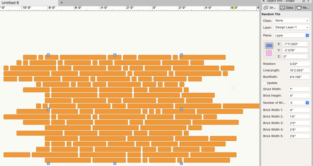
The .vso attachment is a plug-in tool. You can install it in your workspace and it runs like any other tool. It lets you draw an area and it fills in with random rectangular tiles using the settings in the OIP for tile size and grout size. When you change the size of the area it just updates.
In the image you can see the handles showing the adjustable size of the area to be filled and the settings in the OIP.
My thinking was one could use it to get a pattern you liked then convert it to a group and trim away to make if fit the hardscape area.
I'm sure there is a cooler way. Maybe draw the exact polygon, but then how do you set the angle of the tiles? This is just a quick test to see if I could generate random tile layouts using 2 to 5 tile widths. I like to do things like this on flights instead of actual work and I had a 2 hour flight yesterday. That's enough time to test this idea, but not enough to make a hardscape path that turns corners 🙂
To install the .vso:
Vectorworks > Preferences > User Folders tab > Reveal in Finder
This will open up your user folder in the finder. Look for the plug-in folder. Put the .vso file in the plug-ins folder.
Restart Vectorworks.
Tools > Workspaces > Workspaces…
You will see a list of all the workspaces you have. One will be hightlighted and have a checkmark. Duplicate that one. Put the checkmark next to the new duplicate. Edit the duplicate.
Give the workspace a meaningful name. I like to use the basic workspace it's based on followed by the date. So it might be Architect 24 1 2 or Landmark 24 5 6.
Click on the Tools Tab.
On the left side will be all the tools you could be using and many that you are using. On the right are tool palettes. You will see Basic and Tool Sets. Open up Tool Sets and you will see Dims/Notes and Building Shell and Site Planning, etc. Those correspond to the tool sets you are used to seeing in the tool palette.
On the left column look for a folder called MK Commands. In there you will find Random Tiles. Drag Random Tile to be inside of one of your tool palettes on the right side.
Be careful that you don't set it as a "Sub Tool". If the new tool is offset to the right in the list drag it up or down and move a little left so it lines up with all the other tools.
Click OK Now Random Tiles will be a tool in whatever tool set you picked.
Click on the tool and draw a rectangle. The first time it runs it will put up a dialog to confirm default settings. Ignore that. Now you have a rectangle with random tiles. Play around with the settings until you get something useful.
Post back if you have any problems installing the .vso or using the tool 🙂
-
1
-
-
I see it in your styled doors, but not in generic doors. I couldn't make it happen by creating a styled door.
There must be a setting in your door that it doesn't like.
I also notice that the handles for the misbehaving door are offset in both 2D and 3D. That must be related.
-
I tried making a quick plug in object that will do something very close to what you are trying to do.
Really interesting problem. Does this get close?
-
1
-
-
This file was created with an educational version of VW. Professional licenses can't open it.
If you contact VW directly they can convert it to a professional license.
-
It could be off the edge of a monitor. Maybe with just a strip two pixels wide showing.
Try pressing the Classes button and unplugging all the monitors but one. Or change the resolution to something comically small.
-
1 hour ago, Mark Aceto said:
For clarification, it's not a hybrid symbol; it's an auto-hybrid plugin object. That means VW is drawing the 2D in real time parametrically based on the... parameters... entered in the OIP.
Good point, Mark.
It's confusing because they both live in the same place in the resource manager and only the color of the name sets them apart.
-
If you still need a 2D representation, once you get the 3D symbol rotated in to place you can use AEC > Create Auto Hybrid.
-
PS iF you use the HVAC Elbow Duct Tool in the MEP toolset and set the values to be Type: Round and the angle to be 90 you will get the same object.
In the OIP go to Style and choose New Plug-in Style from Unstyled Plug-in…
Give it a name and it will save it as a red symbol! That's where this symbol comes from. That's why it resists being edited.
-
1
-
-
The reason it doesn't work the way it seems like it should is that the symbol you are using is a red symbol. (If you look at it in the Resource Manager you will see the name of the symbol is in red). This means that it's actually a group of settings for a plug in object. It's like a Marvin door. It's still using the door tool. But the symbol contains all the settings to configure it to be a specific door.
To get what you need:
Place the elbow in the drawing.
Go to any 3D view.
Select the object.
Modify>Convert>Convert to Group (Command-K on a Mac/Control-K on Windows)
In the next dialog box choose Don't convert sub-objects to groups
This will give you a group. Ungroup it and you will have the sweep.
Then make the symbol you want:
Select the sweep.
Modify>Create Symbol
In Other Options make sure that Convert to Group is NOT selected.
Now you will have a symbol that can rotate any way you want.
Keep an eye on the colors of symbol names.
Black - normal everyday symbol you meet walking down the street
Red - A parametric object (like a door, window, plant, etc) with a specific set of parametric values
Blue - A symbol that stops being a symbol when inserted. If more than one object is in the symbol it converts to a group. If only one object, then it converts to just that object. The link to the symbol is broken when the symbol is inserted.
Green - A symbol that ignores scale. It's alway at it's page size.
-
4
-
-
Merged cells won't survive either a row insertion or a copy paste.
To make it faster I use these menu commands to format worksheets:
https://www.verysmallgroup.com/worksheet-formatting-scripts
You can either use the scripts as scripts or menu commands. I prefer menu commands because you can assign a keyboard shortcut to merge cells, split cells, etc. There are also commands to copy and paste cell formatting without affecting cell content.
-
Great question.
I'll have to play around with it.
It is probably something like Result := SetObjectTags(ClassHandle, __________); where the blank is an array (?).
I would probably set it up with column C being the tags separated by semicolons.
I don't have time this week to work on it, but in a few hours someone else might have it working 🙂 .
-
1
-
-
-


Worksheet database - header row shifts to the right by one column when copied and pasted to another row
in Troubleshooting
Posted
Now I see it!
I didn't realize you were copying to an already existing database row.
I'll write up a bug report.
Until it gets fixed (no guarantee when that will be) you'll have to first right click on the row header, choose spreadsheet, then paste.