


KrisM
-
Posts
134 -
Joined
-
Last visited
Content Type
Profiles
Forums
Events
Articles
Marionette
Store
Posts posted by KrisM
-
-
I would have never thought of that. Why isn't this in the OIP????? Thanks.
-
 1
1
-
-
Is there a way to change the size of the text in the door ID which is part of the standard door tool? I know I can use my own data tag but am curious about this.
-
Just to clarify the instances when I first noticed my hidden line behaviour - Panning, zooming and rotating in hidden line view are all smooth. If I make a modification I get a message "need to re-render ..." which I have since turned off. After the modification, the re-render takes about 4 seconds. This is what I was commenting on. Should have been clearer. I am coming to VW for it's flexible graphical output but this something which I think could be improved.
-
OpenGL is not the issue here. Both programs handle OpenGL well. The issue is that Revit will do hatches in OPenGL and VW doesn't. To get hatches in VW, you have to do hidden line which is much slower.
-
I am using 2021. Revit is instant even when rotating the model.
-
Seems like Revit and Archicad can display hatches in OpenGL where VW doesn't. Not sure why this is. OpenGL is certainly quicker but still not as fast as Revit. 😞
-
I am wading through my first real project with Vectorworks and am discovering all the idiosyncrasies that one has to deal with. One issue for me is that doing elevations and 3D views and using hidden line mode is painfully slow. I have migrated to VW from Revit and Archicad. I started with Revit and changing views and using the hidden line display with hatches is instant. I changed over to Archicad in search of more possibilities and noticed a lag when updating views. It wasn't too long so I adjusted to it. Now with VW, the redrawing of views is very slow. Make a change in an elevation and it takes 10 seconds to redraw. There must be a fundamental difference in how Revit handles this with how VW handles this. I am not looking for great output yet, just a simple view with hatches and shadows. Any suggestions out there.
-
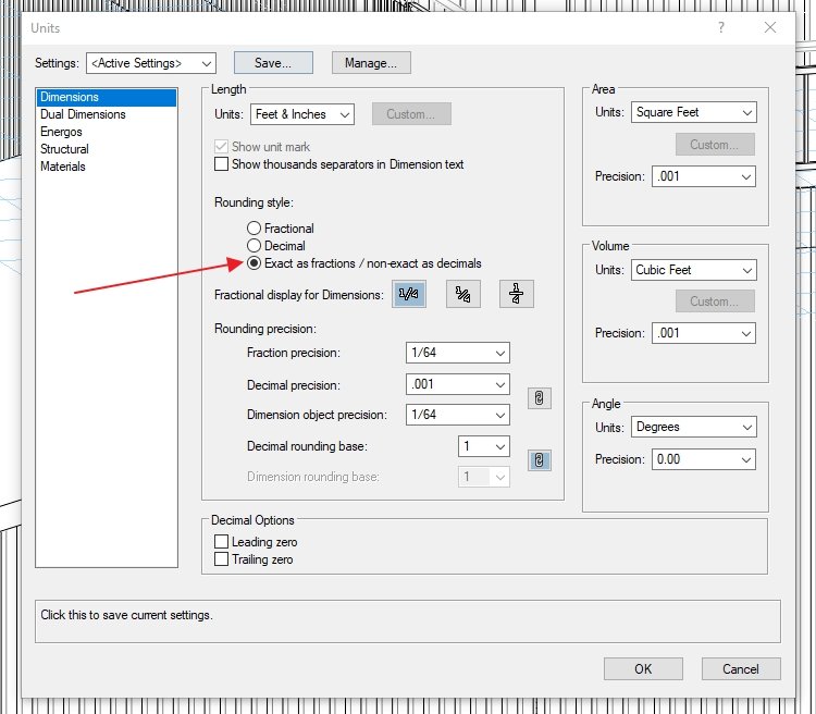
That was the first thing I looked at. Units were set to feet and inches. However I missed the setting below. Fixed. Just a reminder that one should look at ALL the settings.

-
Maybe this will be of use to someone encountering this behaviour -
Yesterday, drew some structural members (beams) and they displayed correctly (three dashed lines).
Today, moved one beam over and it acquired arrows at the end of the beam. I could not find any way to turn off these arrows. The attribute palette is greyed out and there are no settings for the beam to address this.
It seems that the state of the attribute palette at the time of creating the beam is applied to the beam lines. I had an arrow turned on for one end. I can see the logic in this. However, the attribute palette is not available while doing a beam edit.
Solution - Make sure the attribute palette is correct before creating the beam. If the beam is mucked up, make a copy with the correct settings and delete the funky beam.
There have been many posts about the inconsistency between tools. This is a good example. If I draw a line, I can edit the attributes later. If I create a structural member, I cannot do this and have to create a new member to fix it.
-
2
-
-
Found it. Not in any keynote information but rather in the legend information. Another problem solved. Slowly coming to grips with VW's peculiarities. Hopefully I will become productive soon.
-
Can someone explain how to do this? I have searched through the forums and VW help but can't find any clear instructions. I know some people do this. While I am okay with the regular keynote numbering for plan note, on sections I would like a identifier like W1, W2 for walls etc.
-
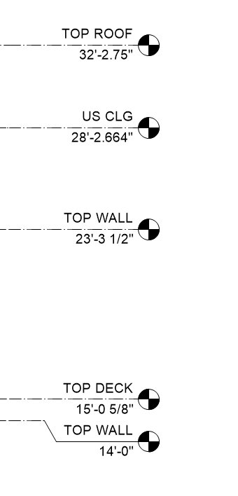
Placing elevation benchmarks for the first time (using 2021). Using control point option. Place the benchmark and get some random number for the elevation but the number is in feet/fractional inches which is correct. Move the benchmark control point to the right location and the inch number changes from fractional to decimal. The dimension format in the document settings is correct. I have no setting which involves decimal inches anywhere in my preferences. There is no way to edit the number preferences in the OIP. Stumped. Any solutions out there other than setting the numbers manually.

-
This is interesting and something I didn't realize. I choose the font size in Word by what looks correct. I never actually measured it. I started off in Autocad years ago and the font size selected is the size of what prints out. Same thing for Revit and Archicad. I tried this again in Affinity and Word. Both times the text comes out at .375" high. there seems to be two standards here and Vectorworks has aligned itself to the publishing definition but Autocad, Revit and Archicad have used a different definition for what the size of a font should be. I prefer the Autocad definition but will adjust to Vectorwork's version.
-
1
-
-
I noticed that the font size asked for and the font size created on a drawing are off. I adjusted all my font sizing to be bigger but wondered if this was a problem peculiar to me. As a test, I created some text is some other programs -
Created text at .500" tall, Arial
Autocad - text was .499"
Revit - text was .510"
Archicad - text was .490"
Vectorworks - .357"
Anyone else see this?
-
Tried that previously and it didn't work. Tried it again and now it does work. Gremlins. Thanks for your help.
-
Tried cut and paste on the buggy beams, pasting them into the correct class. This did not work. The dimension class stayed stuck to the beams.
Tried create similar on the buggy beams and that worked correctly. The beam was created in the right class and displays correctly. I think the structural members have a bug.
-
Tried creating several other objects (walls, doors, slab) in the dimension class and then changing them to another class. They display correctly depending on which classes are turned on. Created two more beams (structural member), one in the dimension class and one in the beam-dropped class. Changed the one in the dimension class to the beam-dropped class. The beam created in the dimension class doesn't display correctly according to which classes are turned on. There seems to be an issue with the structural members class display.
-
I have some structural members which were created mistakenly in a class called dimension. I select the objects and change the class to Beam - Dropped. If I turn off all classes except Beam - Dropped, the beams disappear. they only show when the class dimension is turned on. I copied the beams to a new file and have the same result. As a new user, this kind of thing drives me crazy. I can't find any way in which the dimension class is sticking to the beams. Any answers out there.
-
I have played around with all the settings I can find and I can now get the snap handles to stay on in a selected object but when I move the mouse off a selected object, the highlighting disappears. Puzzled. I have tried in my original file and a new file . Same result.
-
If I look in 'Interactive Appearance Settings', I don't have 'Object Selection - Active Layer'. I have 'Object Highlighting - Active Layer' but that doesn't do it.
-
I can see (and have altered) the setting for a "Object Selecting - Pre Selection" in the Interactive Appearance Settings. What I don't see is the appearance settings for a selected object. It is good to see the object light up during pre selection but after selection and moving the mouse off the object, any highlighting disappears. is there a way to control this?
-
Yes, that was the solution. Don't know how that got changed but now I am now aware of it. Thanks.
-
In addition to my previous post about odd mouse behaviour in the section viewport, I am now getting weird behaviour in my layer views. Two layers - main floor and lower floor. Look at lower floor layer in isometric view. Looks okay. Look at main floor view in top/plan view with show/snap/modify others turned on - main floor shows correctly but the lower floor is showing in the last state it was viewed - isometric view. I would assume my file is corrupt. What is the best way to fix this? I did have some issues the other day when my dimension tool quit working and my data tag too was operating erratically. I had to reinstall VW to get everything back to normal. Any suggestions out there?
-
I am slowly coming to grips with Vectorwork's idiosyncrasies. In Revit or Archicad, I use the section viewports to adjust the heights of objects visually rather typing some number into an information box. I hope to do the same in VW. So I have created a roof object and create a section so I can see where the roof is actually sitting. I choose "edit in place" for the section viewport. If I zoom into the viewport, as soon as I release the mouse, I zoom back out. I cannot zoom in or out and have it stay. This only happens in the section viewport. The mouse operates correctly everywhere else in VW. Am I missing something?
Door ID Text Size
in General Discussion
Posted
If data tags are the way of the future at least they could work in a predictable manner.
The windows are all the same. The ID tag is part of the window OIP and orients properly. The window size is a data tag which references the Window-Width and the Window Height. This is driving me crazy.