


line-weight
-
Posts
3,744 -
Joined
-
Last visited
Content Type
Profiles
Forums
Events
Articles
Marionette
Store
Posts posted by line-weight
-
-
22 minutes ago, Cadplan Architecture said:
I'm using walls today and Reverse Sides flips all the components and keeps the inner and out faces of the wall in position, e.g. it flips around the centre line of the wall. Is this what you mean?
No, I think what @David Poiron means is that it flips around whichever of your components is the "core". In the example of a cavity wall, it's less clear what the 'core' is, but let's say it's the inner leaf, as that tends to be the loadbearing one. So when the wall was flipped, the inner leaf would stay in exactly the same place but the cavity, insulation and outer leaf would move to the other side of it.
It's hard to think of a use case that would arise using cavity walls - more likely with wall buildups where you have a structural component that is centred on foundations and then internal and external finishes are attached to it on each side.
What I would find useful, and is similar in concept, is to be able to "replace" a wall style simply by specifiying that the core component stays in the same place. This would be useful when you are simply changing a wall buildup to one with a different kind of cladding, which might have a different build-up thickness. Walls are generally set out on the basis of the structural component, so once the design is progressed to a certain stage, in making alterations you'd generally want that structural element to stay in the same place. For example, if you change an internal stud wall from one layer of plasterboard each side to two layers each side, you don't generally want to shift the wall to the side by 12.5mm, you want to keep the studwork in the same place and increase the wall thickness slightly.
-
The push pull tool can sometimes fail to select surfaces when there's complex geometry in the background. That may or may not be a factor for you here. You could try turning off other layers/classes and see if it makes a difference.
-
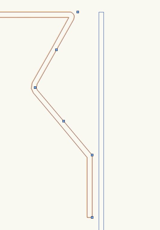
Having now used this tool for a bit - I can confirm that I am seeing exactly the flipping behaviour described above. Working in VW2019.
My hunch - not fully tested - I think it's related to situations where the invisible line that connects the start and end points of the undelrying polyline crosses the linear material object itself. And it perhaps something to do with the proportion of the object that sits on one or other side of that line.
-
Did someone actually decide that's a user friendly way to do something? Amazing.
You'd think you might design it so you activate the window tool and then place the window directly into the roof object, like what happens with a regular window in a wall. But instead there must be several counter-intuitive intermediate steps with some traps to fall into along the way.
-
 2
2
-
-
2 hours ago, khumenny said:
line-weight,
Not sure what you're implying...
But after decades of 2D CAD and building 3D surface models separately, and now being able to combine the two into one, BIM definitely means something to me.
How else should I have described this model?
https://www.vectorworks.net/en-CA/architect/bim
Well I guess the way I see it, there is not really an agreed definition of what BIM is, or at least it seems to mean different things to different people. Does something being represented in 3d make it "BIM"? Is some kind of 3d representation necessary for something to be "BIM"? I don't know.
As @bcd mentions, some people seem to think BIM means "Revit model".
How would you define it?
Maybe it should be the subject of another thread.
-
11 hours ago, khumenny said:
bcd,
BIM model, if you don't know you should look into it, it'll change your VW life.
"BIM model" doesn't really mean anything. Or at least, the scope of what it could describe is so wide as to be meaningless.
-
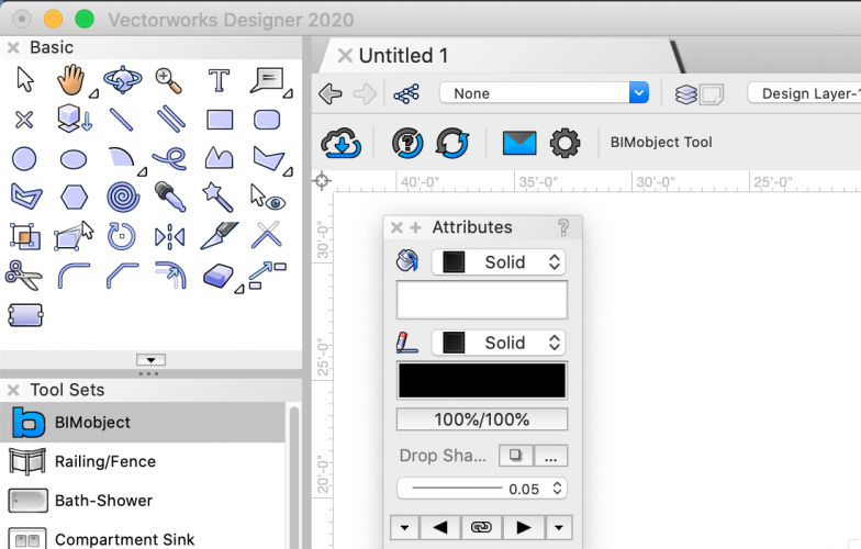
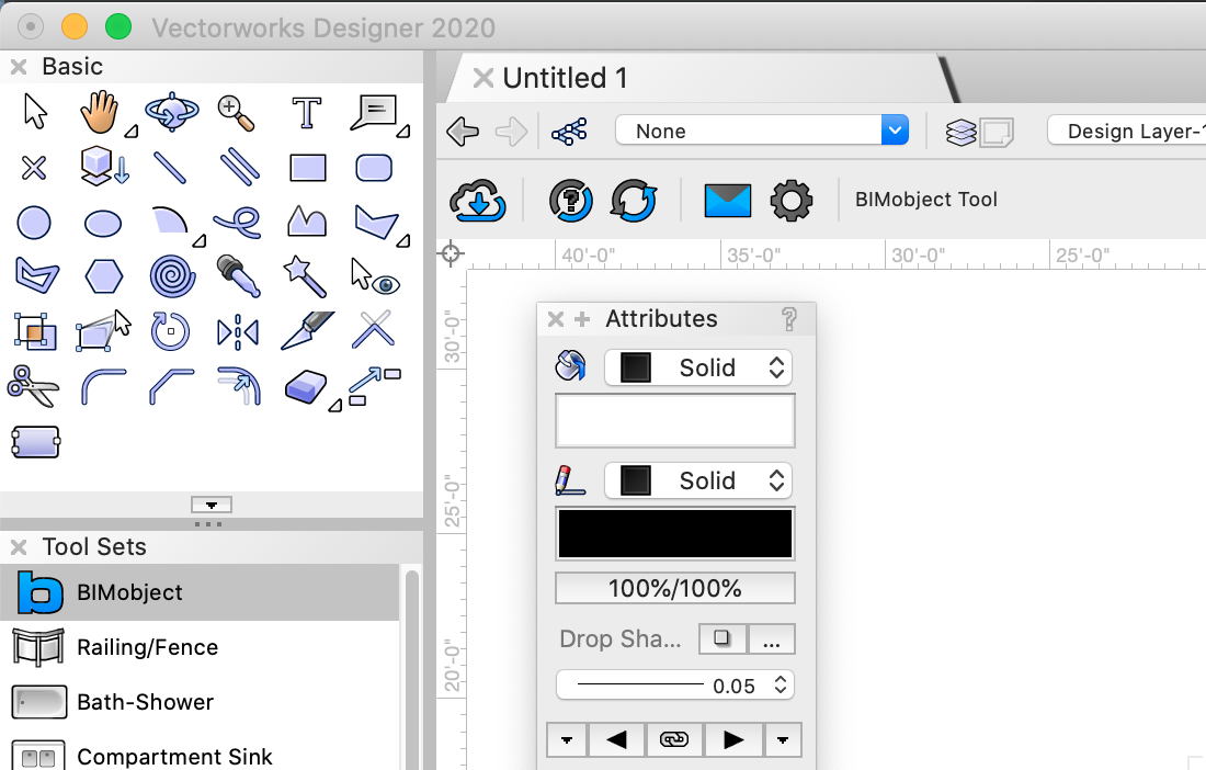
25 minutes ago, Rob Books said:
if you use the bimobject tool, it will show you want you can import to VW, and will often import non native objects in as vw objects.
As per my question to @Wes Gardner, have you ever used the bimobject tool to import something that is then useful in a real world application?
This is not a trick question; I just wonder whether anyone at VW has really tested it, in an attempt to understand whether it is actually of any use to users.
-
5 hours ago, Matt Overton said:
They could actually get long way towards this by creating a best practice workspace for each version.
Best practice would have one monster leap to start with but after that pain would be no worse than normal update.
For Instance no more move and move 3d commands just Move that has x,y,z altogether.
All the most modern tools could be surfaced, given the best short cuts so soon enough we are working better faster. Free up key commands. Yes we can do this but then everyone new doesn't want to use our standard because it's not the program standard. New users are being in effect trained to use the software badly and get stuck in old ruts.
Would be a massive win in terms of the programs outlook.
Yes, that would be a start.
The move / move 3d is quite a good example.
And what's with having an "edit" and a "modify" menu with no obvious logic as to what goes in each?
-
4
-
-
- Popular Post
- Popular Post
8 hours ago, digitalcarbon said:The reason the 1950s roads started to choke was the influx of cars after WW2...they could not handle the increased speed and traffic...
So the solution was not to upgrade the existing roads but to build Interstates.
Actually, that was a terrible solution - it just generates more traffic and then you have choked interstates, air pollution and a nationwide town planning catastrophe.
The solution is to reduce the number of cars by encouraging people to use more efficient and less damaging forms of transport.
To force this into a Vectorworks analogy - don't keep fixing the clogged up dysfunctional parts of the system by building new parallel bits and bypasses and filling them up with new, badly maintained cars trying to get to to chaotic out-of-town shopping complexes miles away. Sort the problem by fixing all the potholes and building us some well organised shops stocked with the best version of each of the things we need, within walking distance so we can get there without trauma and wasted time.
-
5
-
5 hours ago, Wes Gardner said:
You can try here:
@Wes Gardner have you ever tried there?
Have you ever found anything in native VWX format that's actually useful?
-
Thought I'd call by at this thread to do the now annual update, and edit the title, so we can now make a futile wish for 2021 to be the one where existing stuff is properly fixed, instead of having new semi-functional stuff introduced.
-
There are hardly any. There are very few companies which provide BIM objects in VW format and that's unlikely to change. Sad but true.
-
11 hours ago, Mark Aceto said:
Thanks for reviving that thread. VW is due for a maintenance release (not a rebuild).
Meanwhile, Apple is long overdue for another 'Snow Leopard.'
Should I change it to the same wish for 2021 now?
(I've not used 2020 yet. I don't get the impression that there is a consensus it's fixed the various long running problems though)
-
- Popular Post
We've been complaining about this for about 100 years now and very little has improved, in terms of fixing existing broken stuff, and making things more consistent. So I doubt much is going to happen in the next 100 years. @abshapi see this thread:
https://forum.vectorworks.net/index.php?/topic/49017-my-wish-vw2020-to-have-no-new-features-please/
Your experience is the same as mine - the closer you look, the worse it gets. It's become a familiar process - I decide to try out some tool that I've not really used before, because I think, let's invest some time in better understanding VW and taking better advantage of all it has to offer. After a day or so of investigation, in perhaps 75% of cases, I don't arrive at a point of "great, now I understand this and can use it to make my work more efficient" - I arrive at a point where I've figured out exactly which bits don't work at all, which bits of the interface are needlessly confusing, and often, that the conclusion is that the tool is effectively useless. Then I write a thread on here complaining about it, including often a quite detailed explanation of the problems (other posters do this too) there's a half-acknowledgement if I'm lucky, and hardly ever are any of the problems fixed.
The door and window tools are the classic and most outrageous examples of this.
-
9
-
Roofing membrane which can be around 2mm is something that I often find is helpful to draw as a double line at larger scales, to clearly show things like lapping details.
If you show a lapping detail of two elements, and you are using solid single lines, then you have to be careful to make sure that they are somewhat thinner than their 'actual' thickness in order that they are legible as distinct lines.
-
1
-
-
41 minutes ago, bcd said:
Could you use a combination of both?
The single Polyline to represent the flashing, and then convert to Walls.
You retain the Polyline for future edits.
Yeah...but then you might as well just offset the polyline.
-
1 hour ago, Boh said:
I find when detailing flashings in 2d sections there is a lot of editing of them before the detail is actually finished. Why not just use a single poly line set to a line weight to match the flashing gauge? Much easier to edit.
I think sometimes that can work fine... but then you can get into problems with lineweights working at different scales, for example if you have a 1:10 detail and a 1:5 detail, and you have chosen lineweights for 'cut' lines and 'elevation' lines, you want those lines to be the same weight at each scale, but if you have another linetype that's supposed to match the actual thickness of the material then you want those lines to be twice the weight in the 1:5 detail as in the 1:10 one.
-
Hm, the filleting seems to work a little inconsistently for me, on walls.
Assuming it works fine though... moving a corner does mean the following steps:
- delete fillet
- move end of wall segment 1 to new location
- move end of wall segment 2 to new location
- re-fillet.
Not too bad, but with the linear material tool, in theory the same operation involves only one step (or two if you include double-click to access plyline edit mode).
-
1 hour ago, bcd said:
Laugh not, but you can also call the Wall tool to action here.
It's 2d (Top/Plan) depiction should give you what you need:
Benefit of multiple, highly customizable, connectable components.
You can Fillet a corners to produce a curved Wall- and wall joins will elegantly allow you to keep your membranes continuous.
AFAIK sometime in the middle of the last century the double line tool was was first conceived of to draw walls.
The fillet command doesn't work on walls for me... I get this
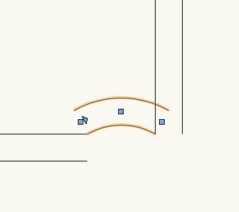
Also... assuming I could get a curved join between the two walls, would I be able to pick up that corner by the imagined intersection of the two straight portions, and move it precisely to another location (ie what would be the steps to make the change shown in my 2nd/3rd screenshots in my previous post?
-
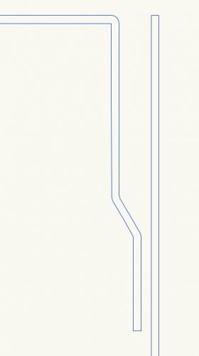
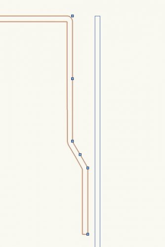
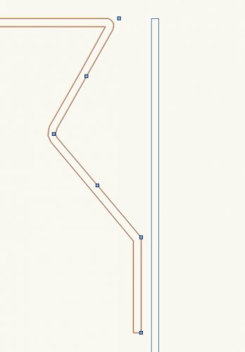
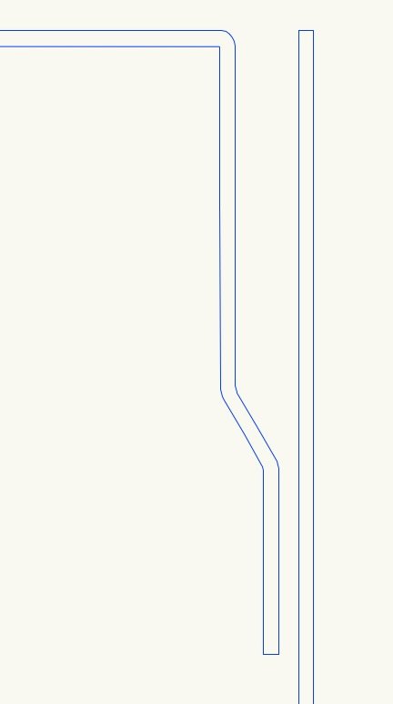
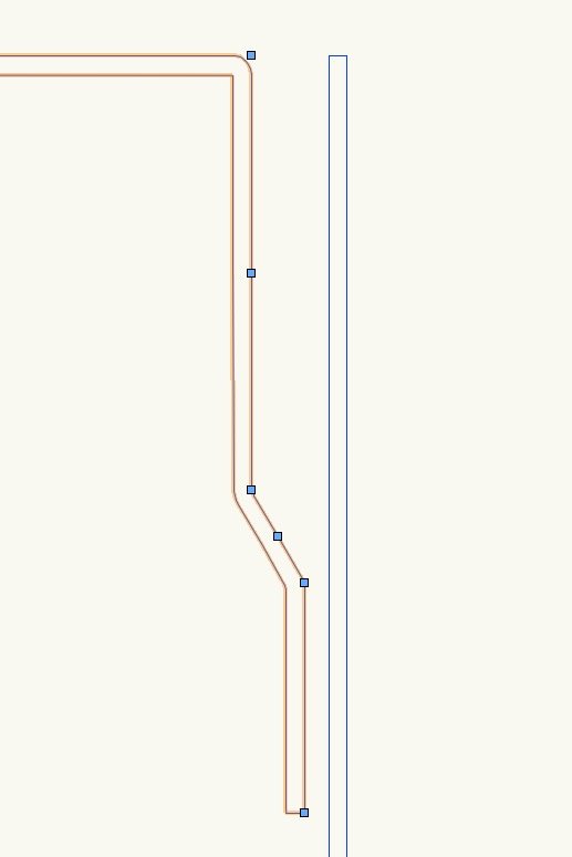
I'm currently working on something where there are quite a lot of details involving roofing membrane, folded metal flashings and so on, where I want to draw these elements as a double line, with radiused corners, and crucially easily editable/adjustable. Previously I might have drawn a polyline, filleted the corners, then offset by the thickness of the material. That is then a pain to edit retrospectively. This tool (so far) seems quite useful for this purpose. Changing from the 2nd to 3rd arrangement illustrated below simply involves moving one vertex on the object.
At the same time I've discovered the "fillet point mode" for polylines which I'd never noticed before, and am going to be using a fair bit for lots of things from now on I think!
-
Bumping this thread, as I've only just started trying to use this tool. 2 questions:
1) As per the above discussion, is it still the case that essentially you can't really customise it? There's no such thing as a user defined 'linear material style'?
2) Do you use it in practice, and is it reliable? I found another thread that suggests some people find it glitchy ( https://forum.vectorworks.net/index.php?/topic/64420-linear-materials-flipping-vw2017/ ). Am I setting myself up for problems if I start using it a lot?
-
- Popular Post
- Popular Post
Realistically (in my opinion).... we are never going to get VW-specific parametric BIM objects for anything other than perhaps a tiny proportion of products. The user base is simply too small. Even if the Velux ones were updated... the reality is, that if you are specifying rooflights you want to be able to choose from manufacturers.
Ended up making some Fakro rooflights in 3d a while ago, by importing some other format, and doing a lot of manual fixing and messing around to get something that actually was any good to use in a working drawing.
I think we should entirely give up on any idea that companies are going to make stuff specifically for VW. Instead, we need:
1) Better automated import/conversion of 'standard' filetypes - Revit, IFC, whatever
and/or
2) A decent, reliable, customisable window tool that can get 'near enough' to a manufacturer specific system. With a rooflight option
I'd rather spend 2 hours tweaking the settings of a good window tool to create something that near-enough emulates a manufacturer's details, that is then parametric (I can use it to make various instances of that system with differing sizes and configurations), than spend half a day bodging together a 3d model from scratch, which is non-parametric and requires further manual modelling work to create each instance, or each time the design is revised and the window size is changed by 50mm.
It's truly infuriating that we still don't have functional window and door tools, while VW marketing materials try and pretend the software is 'BIM ready'.
-
5
-
2 minutes ago, Christiaan said:
That would necessarily require extremely good communication, to know when others are working on files.
Having a whatsapp group for this purpose seems to work quite well!
-
10 hours ago, Mehlkraut said:
Any news on this? Would love to have full VW functionality on the iPad Pro
Let's focus on full functionality on desktops first...

Vectorworks is REALLY SLOW lately!
in Entertainment
Posted
I think this can help, yes, it's something that I do. Plumbing fixtures are a typical source of problems, and I often have a class that I can turn off in 3d which makes certain operations run much more smoothly (for example I find the push-pull tool in particular can stop working when there are meshes in the background).