


line-weight
-
Posts
3,744 -
Joined
-
Last visited
Content Type
Profiles
Forums
Events
Articles
Marionette
Store
Posts posted by line-weight
-
-
1 hour ago, Taproot said:
@zoomer Sorry to hear that ... but hey that's a pretty good run. I'm just amazed that the light source is still good after all of those hours.
@line-weight We're using VW2020 Designer (latest service pack).
Here's what the primary view pane looks like when it starts to go buggy. Part of the image displays at a different scale. In this example, I had just one other viewpane open.
Yes, that's exactly what I get. This has been a problem for some time. I raised it in the thread linked to below (see the video there), but I'm pretty sure it has been mentioned by others earlier than that.
Disappointing but unsurprising that 2 releases later VW have still not fixed this.
-
On 7/18/2020 at 8:07 PM, Taproot said:
I was just working on a complicated drawing that necessitated having multiple panes open at once. The functionality was great! It took two sections and a plan simultaneously displayed to understand what was going on. However, I noticed that after a while, the main drawing window didn't refresh correctly and the section displayed disjointed chunks of the image (like a puzzle before it's put together). We've seen this bug before elsewhere ... while zooming in and out the image draws correctly, but when stopped it blows apart. Suffice it to say that when I closed the other panes, the main drawing window rendered correctly again.
This is exactly what I've experienced and one of the reasons I've largely given up on multiple panes. Which version of VW are you on?
-
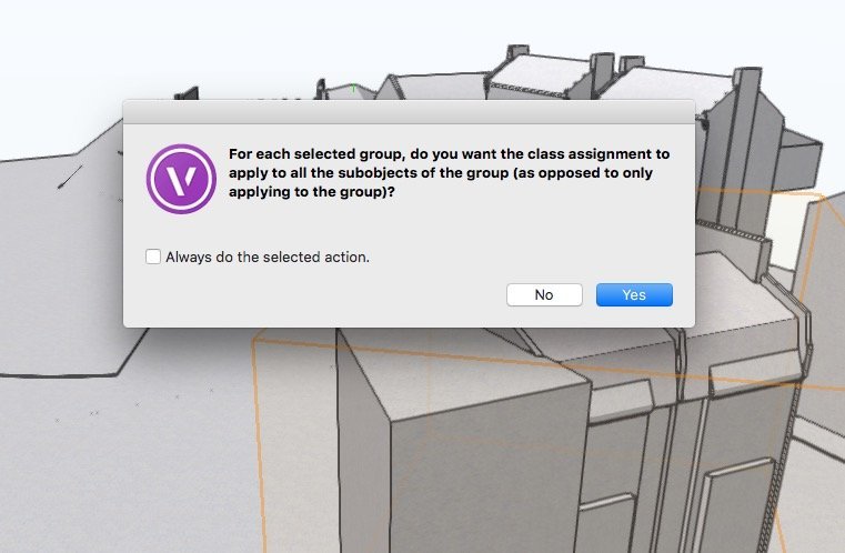
VW is always trying to wind me up by sounding the "error" bell whenever this popup appears.
It's like it is impatient for me to tick the "always do selected action" box because it's bored of asking me this question. Well, sometimes the answer is yes and sometimes it's no.
-
 1
1
-
-
That would make sense. Let's see. Where was this previewed though?
-
12 hours ago, jeff prince said:
I use this occasionally on my laptop when creating items in 3D or wanting to reference items on a different layer that I don't want to see in my active pane or is not available in my active pane because it exists on a sheet.
If I was setup on dual monitors, I would probably have a dedicated perspective view pane running all the time during 3D work.
I find it is exceptionally useful for placing and sizing items like doors and windows on an existing context model when you have no measurements 🙂
When the two panes are on the same screen like this, it's fairly easy to move between either of them, and the tool palettes. When a pane is on a second monitor, there's then a rather long journey for the cursor to make back and forth (plus my muscle memory keeps wanting to look for the tools in the normal position relative to the active drawing pane).
How is this dealt with in other applications - do they repeat the tool palettes on the second monitor? I think that if VW did this, it might be easier to use in this way.
-
No comment from anyone at VW then?
-
It sounds like most people have come to the same conclusion as me - the floating pane configuration doesn't really work.
That several people have said they do use something similar in other applications suggests that it's just a poor implementation in VW. Which is a shame because with a bit of effort it could surely be made to be more usable.
-
1
-
-
I'm interested to know how many people use this in practice.
Do you regularly work with multiple view panes and if so, do you have any of them arranged as "floating" panes and on another screen in a multiple monitor setup?
I'd like to be able to work with two panes - one on my main monitor and one on a secondary monitor. Every time I try to do this though, I give up; it's just too awkward, I keep activating saved views in the wrong pane by accident and selecting tools is fiddly. On top of this there are various graphics errors that appear once you have more than one pane in operation, and it's my feeling that it causes various things to go wrong with the drawing too... floor slabs misbehaving, things like this.
I'm still using 2018 so maybe some of these things have improved in subsequent versions.
Or is it one of those Vectorworks features that is introduced as 95% functional and then never touched again, meaning hardly anyone actually uses it? Is it worth me persevering?
-
1
-
-
Thanks, at least you are able to replicate it.
It seems to be that the combine/connect tool applied to roof faces is unreliable/inconsistent, and/or there is something wrong with roof face objects themselves.
-
Any thoughts on this?
-
9 hours ago, Boh said:
In your video workaround for stacked wall finishes I am wondering if instead of using a door object to create your cutaway in the wall it might be better to create an appropriately shaped extrude, turn it into a symbol and set it to insert in walls with a full wall break and also place it on a NonPlot class. The Symbol/extrude I think might be easier to create and edit than a door object and can be any shape you want. I quickly did this vid to demonstrate.
That was my thought too, as I think the door method would constrain you to symmetrical shapes.
-
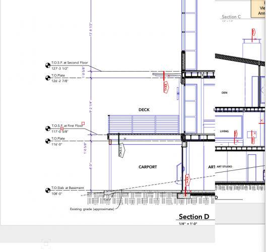
VW simply isn't able to draw things like rooms in roofspaces properly in top/plan, especially when you want to show construction buildup even at a basic level of detail. For example in the drawing in the video there is an external finish and insulation shown in the dwarf walls that separate the eaves spaces from the room.
Best in my view to draw them as horizontal sections, and just use solid modelling (or possibly stacked wall objects) for things like this. More flexible and probably no more cumbersome/time consuming to draw and edit.
-
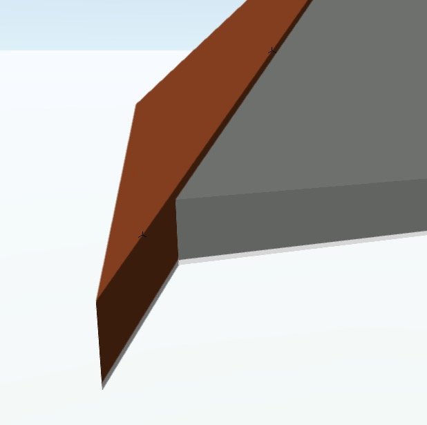
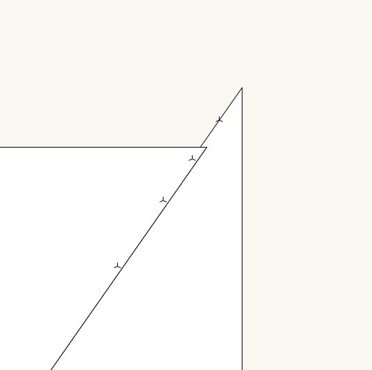
I've got two roof faces which meet each other at a vertical join. If I look at them in 3d, I can see that the 'inner' faces are aligned at the join, but the 'outer' faces aren't. This is because the two roof faces are at different pitches.

(Am I correct to understand that the reason they are aligned on the inner face is because this is where I have set the "datum" for the components on each?)
But when I look at this in top-plan view, they are drawn as if they are overlapping. Why is this?
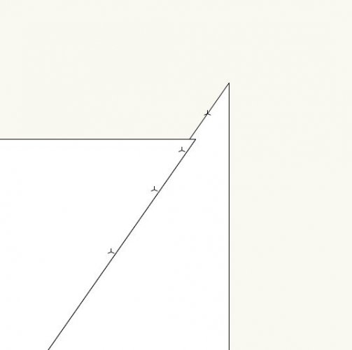
You can see that I have placed a few 3d locii to check that the "join" face is vertical. You can see them in the top-plan view. I've attached the VWX file.
-
2 hours ago, FBernardo said:
Do you want me to create a video showing how i usually do it? i think it's a lot easier to show than to explain in words!
But you are right the Roof "dormer" way VW uses is quite a gibberish in comparison with other tools that are quite easy to use and with all the mojo of easy to use philosophy!
What kind of issues have you found with the Textures by class and using in the components? I use it this way and it seems so much easier and quick also works wonderfully!
I think I mostly understood about how you draw them - thanks - so there is no need to make a video, although it might still be interesting to see.
With the classes (actually it may not be related to textures as such) - the specific thing I noticed was:
1. Viewing in OpenGL with "use textures" and "use colours".
2. I assign a "material" class to each component, and each class has its own "fill colour".
3. I then edited one of these classes, to change it's "fill colour".
4. Then, viewing in OpenGL something strange was happening, the relevant component would sometimes appear with its "old" colour and sometimes with its "new" one. It would change when I shifted the view around.
5. Changing the render setting for the roof face object from 'by component' to 'by object' and then back to 'by component' seemed to fix it.
-
On 8/19/2016 at 1:55 AM, Jonathan Pickup said:
try Edit Group from the Modify menu
I'm having problems with this too.
When I select the clipped roof object, "edit group" is greyed out in the menu.
-
43 minutes ago, FBernardo said:
The way i've found to be easier to me is drawing the dormer from the walls and cut the roof where the walls are sitting and then add a normal window and a roof on top of those walls and join both roofs. Later i'll edit the walls as to how they're going to be in construction, so the bottom of the wall is going to be on the bottom of the main roof.
Yes, having tried the dormer tool out a bit more now, I've decided it's not all that much use, except maybe if you want to show something indicative at an early stage.
- as far as I can see, you can't go back and edit the window easily, because although it exists as a symbol, it's no longer a plug in object so you can't make adjustments to it in the same way that you would to a normal window-in wall
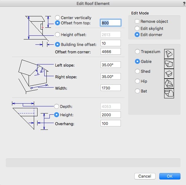
- it seems that the only way you can adjust its location in plan is through typing numbers into the dialogue box in a trial-and-error kind of fashion, which isn't even updated live, so you have to keep closing and opening the dialogue to see if you have got it right yet
- the controls themselves seem rather confusing, with various options to offset and so on, but little information about where the reference points actually are, how they relate to what points on the symbol, and so on.
Even roofs/roof faces themselves (which I've not used a lot until now, but they do seem useful to an extent) are a typical VW jumble of confusing, inconsistent and anti-intuitive commands. And something weird seems to go on with textures and classing by component and so on.
-
13 hours ago, Robert Darden said:
I created a dormer by dragging in the window into the roof in isometric view.
However, I want to modify the window, but can't - the program only allows editing of a skylight.
Please advise, thanks!
When you get into the edit dialogue for the dormer/skylight, in the top right you can choose between dormer and skylight. It's not well worded - "edit dormer" implies it's a function to edit an existing dormer whereas really it should say "create dormer".

-
I just tried creating a dormer window for the first time. I've not tried using this before.
I ran into exactly the same problem as @domer1322 above. I followed all the instructions, including the create a symbol bit, which isn't properly explained in the user guides, and activated the symbol, and tried to insert it into a roof face. Nothing.
I remembered this thread. So, reading it, yes, you have to *drag* the symbol from the resource browser. As identified above. But not stated in the VW documentation.
Thank you @domer1322.
It's absolutely dreadful, this. How to annoy and frustrate your users, for no apparent reason. It should win some kind of award for terrible design.
-
No word on this from anyone at VW?
-
Another thing that is a bit of an art ... and especially when you work in 3d.
You measure the ground floor and the upper floor, and drawing each one individually all works fine.
Then you overlay them and it doesn't. In 2d you could to some extent pretend it wasn't happening. Maybe you would bodge things around so that at east the staircase makes sense. If the proposed work didn't involve connecting the two levels in new places... it didn't matter too much that the chimneybreast on one level was 100mm away from the one below.
Can't really get away with that in 3d. It'll show on the elevations at least. So you have to do a bit of "rounding", and decide which dimensions are the important ones, which might be the ones relating to bits you know there is going to be work done to. The alternative is to draw the walls as they actually are... not vertical. Which VW doesn't really like.
I assume that point clouds don't make this any easier.
-
2
-
-
On 6/20/2020 at 1:31 AM, jeff prince said:
@line-weight thank, glad you found it interesting! My wife’s eyes kind of glaze over when I triumphantly present my latest work 🙂, so I post this stuff here for your enjoyment. I also kind of hope the folks at Vectorworks are paying attention to this workflow. It’s huge, usually with LIDAR, in aerial survey, environmental analysis, large scale construction monitoring, and infrastructure planning. It’s gaining a foothold in design as well. I used to hire a plane to do this kind of work, now I can do it with a machine that fits in my backpack.
I agree with your comments on detail and accuracy, it’s certainly not survey quality work. Part of interpretation and tracing revolves around knowing the construction type. If you have something that is block modular, rectilinear, and built by a reasonably skilled crew... you can get within 1/2” in most cases 🙂. Having the knowledge about how things are built goes a long ways in quickly recreating things without measuring. Architecture can usually benefit from a ground based scan and be highly accurate when required. I do this mostly as a professional challenge for myself and to save time with data acquisition. It’s pretty nice to be able to review the entire site visit from oblique aerial photography. There is all kinds of stuff you miss when walking around a large site. Plus, the wide aerial vantage point reveals patterns in the landscape that are difficult to perceive from the ground or on Google Earth.
That handrail on the stepped wall at the end was pretty fun. It was built off the drone footage and a walk thru video. I measured it today just for comparison and to develop a construction detail should I decide to mimic it elsewhere. The only bust was on the rebar pickets ( I faked it with a texture), height of the lower rail (Off by 1/2”), and connection details (couldn’t see). I got the slope of the steps (block modular) and steel framing (Assumed standard profiles) correct. 20 years ago I would have struggled with all that because I didn’t have the needed experience. Now it just flows during modeling.
The drone I used on this was a 1st generation Mavic Pro. I used to have an Inspire as well, but the lower flight time was problematic. While the mavic camera is not as nice as the Inspire, it is more than adequate when configured correctly. I probably have about $2000 into it with all the accessories (batteries, props, memory cards, camera filters, ipad holder, glare hood for the ipad, etc). I fly it with my iPad for these kinds of jobs, so that’s an expense that should be factored in. Doing it on a phone is okay for motorcycle videos, but on not on this kind of work. I like to see the photos it is taken on the iPad so I can see if I got the focus and other settings correct. That’s very difficult to do on the phone. If you shoot 300+ photos of a site and find out they are out of focus when you get back to the studio, it’s heart breaking and makes digital mapping less accurate. I unusually shoot two sets of the same photos, but with slightly different settings, as cheap insurance. That’s where having lots of batteries and memory cards is a benefit. Oh, I almost forgot the software for reconstruction, that can get pricey depending on what you use. I bought the drone to take photos and video of my adventures and already had an iPad Pro for other purposes. Only later did I develop a method for using it for my work due to a lack of aerial photography in the country I was in and having a lot of time for R&D with my employer. If I didn’t have all the gear already and an interest in figuring this out, I would just hire one of the many companies out there to collect the data for me. Drone based aerial photography is a cutthroat business in the western US. There are a lot of hobbyist shooting real estate, they should generally be avoided because they usually can’t actually produce maps or engineering data. If you find a skilled map maker who is reasonably priced, keep their number handy.
hope it helps,
Jeff
There is certainly an element of art to surveying, and you become better/quicker at it the better you understand how the building type you are looking at is put together. You also get to know which are the really critical dimensions, and which are the ones where it really doesn't matter if you're a little bit out.
Where I do most of my work, the block module is often a hand-made and hand-laid brick, but on soft ground with virtually no foundations so one of the things you learn is not to assume horizontal lines are horizontal! That said, you can often get pretty close by counting brick courses for heights.
I'm keeping an eye on this drone surveying, to see if it's something that will become easy/affordable enough for me to start using in place of X hours measuring up manually. There is an engineer I have worked with who uses it a bit ... however some of his efforts have been frustrated by limitations on where and how high you are allowed to fly in densely built up urban areas.
In fact what I'd most welcome becoming automated is the surveying of internal details... measuring up multiple rooms with similar but not identical arrangements, trying to get diagonals with furniture in the way, all that can be pretty tedious. Would be nice just to put a device in the middle and get a point cloud - but before starting to try doing things that way I'd want to be confident that VW can actually deal with it, and it feels a bit like we are not quite there yet.
-
4
-
-
@Boh Do either of the worksheets work OK when you want to include a drawing in an issue which hasn't had a revision since the last issue?
For example, in "third issue B3" from your screenshots above, if issue 3 had included "elevations proposed" but issued again as revision B (rather than a new revision C)?
-
5 hours ago, Nikolay Zhelyazkov said:
- Any feedback on what is expected from the worksheet reports is welcome and considered. 🙂
Your proactive approach is appreciated.
I am still on VW2018 but as soon as I move up to the latest version I will have another go at using this and be sure to bring some feedback here.
-
1
-
-
Looks a bit like the problems I was experiencing, that caused me to lose confidence in the reliability of this.
It's a shame because it's at a "nearly works" stage. VW needs to provide some worksheets that have been subject to intensive testing, because the majority of users are never going to put this much effort into developing one for themselves.


Beams Above
in Architecture
Posted
There's no "best practice" or coherent workflow that VW is designed around, for architectural projects, I'm afraid.
You kind of have to work out what works best (or least worst) for you and the type of projects you tend to do.
One of the big issues is touched upon above: the "top-plan" concept sort-of works for certain kinds of buildings (large rectilinear ones with flat roofs) but falls apart for more geometrically complicated things. Then you can use the horizontal section approach - which has a separate bunch of problems associated with it.
Vectorworks frankly is a big mess - but quite a flexible and adaptable one, which is why many of us stick with it.