


line-weight
-
Posts
3,743 -
Joined
-
Last visited
Content Type
Profiles
Forums
Events
Articles
Marionette
Store
Everything posted by line-weight
-
There's something wrong with the way this works. It often seems impossible to find the legend that's supposedly been created (even using the custom search). I have to resort to copy-pasting one in from another file, and then all new ones in that file are made by duplicating the first one.
-

Pease add vertical aligned text for dimensions.
line-weight replied to Bruce Kieffer's question in Wishlist - Feature and Content Requests
Ah right I see. Yes, I can't see a way of doing that either. -
Pease add vertical aligned text for dimensions.
line-weight replied to Bruce Kieffer's question in Wishlist - Feature and Content Requests
You can do - with pointer tool active and the dimension selcted, hover over the text block, then it lets you grab it and move it anywhere you want. Or do you mean have it align in a certain way by default? There are quite a few things you can adjust in dimension standards -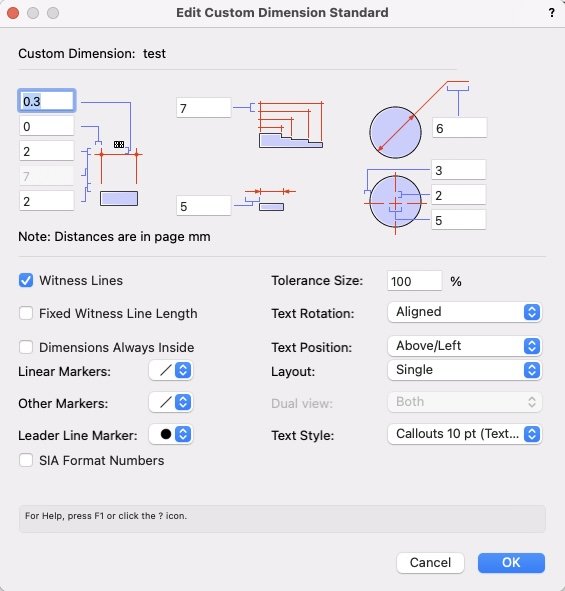
-
Give us a curved leaders option with callouts.
line-weight replied to Bruce Kieffer's question in Wishlist - Feature and Content Requests
I've never noticed that option either. -
The temptation to make a list of all the things that aren't quite correct is hard to resist for me, who gets really obsessed about getting surveys right and spends way more time chasing accuracy than makes any business sense...
-
Hm. I don't think that's happened to me (yet). I wonder if it's a symbol-inside-a-symbol problem? In many cases, my custom doors/windows are actually groups rather than symbols (so the door leafs are symbols within a group).
-
It's quite easy to achieve this if you build your own door objects. Make the door leaf a symbol, duplicate it and rotate one copy 90 degrees. Make two classes, one "doors open" and one "doors closed" and put the instances of the door leaf in each. Then you can choose per viewport which of those classes you want visible and hence whether the doors are open or closed. If you want you can make it more fine grained and control it per door. This of course is not very helpful if you need/want to use VW door objects. However, it makes it feel like it shouldn't be all that difficult to implement for VW doors.
-
Window with symbol: inconsistent behaviour in Horizontal Section Viewport
line-weight replied to line-weight's question in Troubleshooting
I guess that's in "extrude face" mode of the push/pull tool. In "move face mode" the object is immediately converted to a generic solid with no history and loses its status at that point. -
I guess I'm not the only one who just closes this window immediately when starting up VW. One of the reasons is that the list of recent files is not ordered in a useful way. It lists them according to when they were last opened. This means that if I've had a main project file open for a few days, but have a opened and closed a bunch of other unimportant things in the meantime, the main project file appears somewhere well down the list. So I have to go searching for it. It doesn't give me any advantage over just using "open recent" in the file menu. At least there the list is more compact and I don't have to scroll down to see the bottom of it. If it listed files according to "last closed" for example, this would be more useful.
-
Window with symbol: inconsistent behaviour in Horizontal Section Viewport
line-weight replied to line-weight's question in Troubleshooting
So, now to the sill. Again this drawing is produced without any additions/alterations in the annotation space. It basically gets everything where I want it. No components need to wrap into the opening at the cill. However, the internal plaster layer needs to oversail the other wall components and continue up to the underside of the interior sill. This is where it's a bit frustrating that we can't simply specify an "offset" per component. I've achieved what I want by adjusting the shape of the symbol's wall hole component and this works - but if for example I were to change the wall buildup slightly, so that the brickwork layer had a different thickness, or if I wanted to move the window inwards or outwards a bit, I'd have to go and edit the wall hole component manually too. I have fiddled around a bit with the "profile offsets" and "wrapping" settings for the bottom of the window opening to see if I can get it to produce what I want (that inner plaster layer oversailing the other wall components) but as far as I can see, this isn't possible. Am I missing something?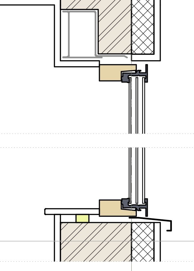
-
Callouts really are a pain. For years I had the habit of hardly ever inserting them "fresh", instead copy-pasting from somewhere else, because it was easier than pinning down exactly what controls their attributes. They also have a confusing behaviour in the way they exist in page/world units. I think you can set defaults in page units but then they convert to world units when you place them - something like that. And copying them between viewports of different scales messes them up.
-
Window with symbol: inconsistent behaviour in Horizontal Section Viewport
line-weight replied to line-weight's question in Troubleshooting
Yes, just as you describe, I've got the lintel as an independent object just placed into the relevant location. But you're right, it could be part of the window symbol and there's a good argument to do that. Would make it easier to move the window position for example. -
Window with symbol: inconsistent behaviour in Horizontal Section Viewport
line-weight replied to line-weight's question in Troubleshooting
It's not...but I guess it could be. -
Window with symbol: inconsistent behaviour in Horizontal Section Viewport
line-weight replied to line-weight's question in Troubleshooting
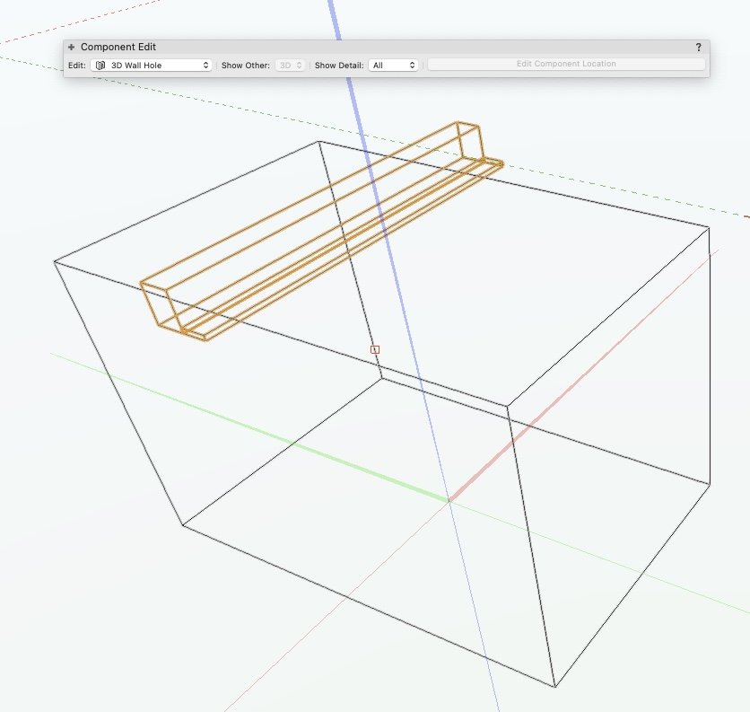
@AHiguera Thanks for explaining how this can be used. Somewhat to my surprise.... I have managed to use it to create this window-head detail (nothing added in annotations here): The grey thing is a folded steel plate lintel. It needs a kind of notch taken out of the brickwork. So that notch/void that the lintel sits in, I made by adding some geometry to the "wall hole component" of the 3d symbol and told it to "ignore wall closure". It takes that chunk out of the wall for me... but still lets me wrap the internal finish under it and up to the insert. I realise this is potentially a (rather complex) way of introducing voids at reveals, as I was asking about earlier in the thread. Only one thing tripped me up for a while - I thought it wasn't working - but it's because the objects in the wall hole component lose their "ignore wall closure" status if you use the push-pull tool on them. This was happening without me realising, and I was wondering why the finish was wrapping itself around the inside of the recess. the wall hole component looks like this - the highlighted objects are the ones that "ignore wall closure".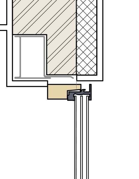
-
Graphic legend - version for non-data objects
line-weight replied to Amanda McDermott's question in Wishlist - Feature and Content Requests
I think part of the problem is that even if there's a way to satisfy a selection criteria, you can't then have a graphical representation of the object in the legend, unless it's one of a few certain types of object. And this means that the "graphic legend" tool just becomes a "legend" tool. -
Window with symbol: inconsistent behaviour in Horizontal Section Viewport
line-weight replied to line-weight's question in Troubleshooting
Ah, I see. Thanks. I wasn't aware of this possibility (nor that the wall hole component can contain multiple objects. -
Window with symbol: inconsistent behaviour in Horizontal Section Viewport
line-weight replied to line-weight's question in Troubleshooting
The interaction between the "profile offsets" and "wrappings" tabs of the wall closure settings makes things a little confusing sometimes...it seems like they operate in their own universes and have to be persuaded to talk to one another. I can see why you might define interior and exterior offsets according to the location of the window/insert. No doubt there are scenarios where it makes sense (for example traditional mass masonry walls where there are often rebates built in for window frames) but it doesn't fit so well with modern multi-component wall buildups. Because in these kinds of walls, if there are any step-backs or rebates they usually tend to occur at the interface between layers. So quite often you will be trying to get a step-in or step-out in the wall opening, to occur at the boundary between two wall layers, but instead you must define it relative to the window/insert object. Which is always, ultimately, doable but takes a bit of fiddling around and possibly a calculator to subtract various dimensions from one another. It would be nice if you could instead define offsets per wall component. That could make some of these gymnastics redundant. Within the wrappings tab, I do think it's very confusing that you can set something to "wrap to insert" and to wrap to another component. Logically it should be one or the other. It seems the actual behaviour is that it will wrap to the insert unless it can't find it in which case it'll wrap to the chosen component. And that scenario is most likely to happen when there's a negative offset, for the reason that @AHiguera explains above (the wrapping element can't intersect with the wall closure component due to the inset). But it's not at all apparent to the user that this is what is going on. Nor is it very helpful to the user, to be unaware that it can't find the "insert". What happens, is it can't find the insert, so it reverts to the "wrap to component" location but the user is still looking at the tick next to "wrap to insert" and wondering why it isn't doing that. They are already confused about the fact that they seem to be able to choose two wrap targets simultaneously. They will now start to fiddle with the "wrap to [component]" setting and quite possibly develop a superstition about one setting over-riding the other, which will not then match what happens in a different situation. In my opinion it would be better if the "wrap to [component]" field were to grey out when "wrap to insert" is selected. If that fails, then ok, it's failed and the user may still wonder why that is, but they can choose to give up on that, uncheck the "wrap to insert" column and pursue a strategy based on wrapping to a wall component +/- an offset instead. The limit of any superstition is then "wrap to insert doesn't work if X" which may or may not be correct but is less likely to lead to confusion in the scenarios where wrapping to insert does work. There could even be one of those pop-ups that are annoying (because they don't tell you why something's failed) but at least confirm that something has failed - "Wrap to insert has failed for wall component X" -
Window with symbol: inconsistent behaviour in Horizontal Section Viewport
line-weight replied to line-weight's question in Troubleshooting
Where does this option arise... which kind of objects? -
Window with symbol: inconsistent behaviour in Horizontal Section Viewport
line-weight replied to line-weight's question in Troubleshooting
@AHiguera thanks very much for explaining this. I'm just trying to get my head around how it works. (Incidentally, it explains a separate problem I was having, which was that VW would refuse to accept my wall closure object but not explain why. It was always after I'd used the push-pull tool to stretch it in one direction or the other and I found I had to draw it "fresh" each time. Obviously the P-P tool was creating an addition of some kind.) About the wall closure object ... why does it get subtracted from what you call the "wall blob"? I'd have thought that's the wall hole component's job, to decide which parts of the wall get subtracted away. I'd have assumed the wall closure component's job is really just to define two planes, the outer and inner planes that any wrapped components stop at so that they don't crash into the window/insert. I don't quite understand the subtracting bit. -
I think you might need to attach some screenshots or an example file because I don't really understand where you are putting the dimensions that are disappearing.
-
Graphic legend - version for non-data objects
line-weight replied to Amanda McDermott's question in Wishlist - Feature and Content Requests
This is a good example of a "real life" legend - and the sort of thing that ideally the graphic legend tool would be able to cope with. It's quite common for a single legend to contain a mixture of attributes, objects, symbols, linetypes and so on. -
Go away – Component Edit palette!
line-weight replied to Kaare Baekgaard's question in Wishlist - Feature and Content Requests
Yes. -
Some people will disagree with me on this, but your dimensions should be in the annotations space of the viewport, not in the design layer. You can get away with in 2d drawing but it doesn't make sense in 3d. In the case of a section - where are you locating your dimensions in the design layer? The section doesn't exist as snappable geometry in a design layer, the cut plane only gets drawn in a viewport.
-
reduce the awkwardness of subdivision modelling
line-weight replied to Kaare Baekgaard's question in Wishlist - Feature and Content Requests
I don't have this problem. But I think it's because I use a 3dconnexion spacemouse for 3d navigation. That temporarily invokes a flyover mode/tool whenever I use it. But it doesn't force me to exit the edit subdivision mode. -
reduce the awkwardness of subdivision modelling
line-weight replied to Kaare Baekgaard's question in Wishlist - Feature and Content Requests
The not-consistent-with-other-tools behaviour of the Subd tool was discussed here recently too.
