


line-weight
-
Posts
3,744 -
Joined
-
Last visited
Content Type
Profiles
Forums
Events
Articles
Marionette
Store
Posts posted by line-weight
-
-
55 minutes ago, markdd said:
They can be "composed" together using the Connect/Combine tool. You will get several options which can be really helpful. It's definitely worth exploring this tool.
Thanks! This is a tool I under-use. I'll make an effort to explore it some more as you suggest.
-
I often have trouble getting NURBS curves to compose with other objects such as lines. The VW documentation suggests that this is supposed to be possible - but is it?
By way of example the attached file has two NURBS curves which I'd like to compose together with a line that joins their endpoints, but I can't make it work.
-
3 hours ago, Tom W. said:
don't be like me + ignore for years the little dims buttons to the side
 : they allow you to quickly take dims direct from the drawing which speeds up the process considerably!
Another thing I didn't know until just now!
-
1 hour ago, Pat Stanford said:
Do you have Fillets or Chamfers on any of the objects inside the solid? It is very likely that they would not automatically regenerate.
Your signature says VW2018 is that correct? There has been a lot of work done on solids for VW2021 so they now understand Chamfer and Fillet history.
Also, you say solids subtracted from a 3D Symbol. I don't think it is possible to subtract solids from a symbol. You would have to convert it to something other than a symbol first. Or I am misunderstanding what you are saying.
yes - this is in 2018.
There aren't any fillets or chamfers, no.
The symbol consists of two solids: an extrude, and a tapered extrude.
Subtracted from this symbol is an addition of two extrudes.
It is in fact possible to subtract solids from a 3d Symbol - this was somewhat to my surprise.
-
What causes this?
I have one file where a particular solid fails to regenerate each time I need to recover it from a backup.
I can copy and paste this solid from an earlier version of the file - and pastes in fine - it's there and correct, but if I try to do anything to it, even just double-clicking into the subtraction without changing anything, I can't then exit it without it failing.
If I copy and paste this same object into a blank file, there doesn't seem to be a problem. There only seems to be a problem when I put this particular object in a particular file.
Is there any way I can fix this? Does it indicate a corruption in the file that I should be worried about?
It's a subtraction where some simple solids are subtracted from a 3d symbol.
-
9 hours ago, Pat Stanford said:
If you are trying to scale an object using the mouse, have you set the fixed point in the Object Info Palette to be the center?
When I do that and grab a corner point of a Rectangle and hold down Command and Shift I get symmetrical scaling around the center point.
HTH
Doesn't help the OP - but I didn't know until now that this was possible - thanks!
-
Seeing as this was raised, and a wish filed, nearly four years ago (if not earlier) and nothing has been done about it, I don't have much hope for anything happening in the next four years.
As @grant_PD says - surely this does not need to be complicated?
Thank you nonetheless for taking the time to write it up again @Andy Broomell
-
35 minutes ago, Jesse Cogswell said:
@line-weight , ask and you shall receive.
Amazing! Thanks!
If only the main bit of Vectorworks worked like this.
-
Yes, this script is great and is saving me a lot of time and tedium on one particular project where I have a large number of viewports with quite complicated class setups.
The eyedropper tool can be slow, not just because you have to go around each viewport manually, but because of the slowness with which Vectorworks opens up and draws sheet layers with large numbers of viewports (something that might have improved somewhat in later versions, but at least in VW2018 which I'm still using, switching between such sheet layers is incredibly lethargic and tedious).
Being able to tick the box that re-renders all the viewports you've just updated also saves quite a lot of time (although, if I had one further suggestion to @Jesse Cogswell it would be that this box should be un-ticked rather than ticked by default, as it's quite easy to unintentionally set VW off on a redraw when you didn't meant to).
-
3 hours ago, Stephan Moenninghoff said:
BTW the object arrays are all done via Marionette. Each green box has a Marionette of just a single symbol which is scaled, rotated and displaced with controlled random values. It's the next best thing to a real gravity and collision control function which Vectorworks does not have.
I think I can spot a few radishes and tomatoes which have intersected with their crates....
-
@Kevin C all my working elevations/sections are produced using hidden line rather than OpenGL. Is there a reason you're not using hidden line? Because that *is* vector based.
There are problems with hidden line... but I just about get things to a good enough standard for working drawings. I generally don't use hatches at all (except for section cut plane) and I also generally stick to black and white only. Traditional style pure line drawings.
-
Could it somehow be a result of the windows being inside-out on the upper floor (ie. they are in a wall which is drawn the wrong way around)?
-
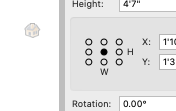
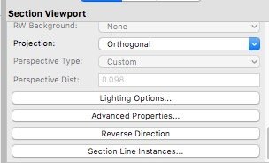
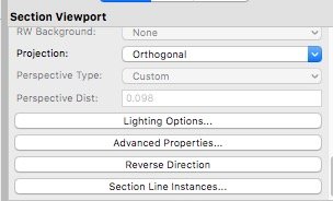
You don't need to manually rotate the section lines - you can just reverse their direction using the "reverse direction"
button in the OIP for the section viewport.
-
I usually set up a sheet layer that is purely for the control of section lines - on there I have a plan (for vertical sections) and an elevation (for horizontal sections), and those two viewports I give easily recognisable names, then I use the "section line instances" control to make all section lines show on these viewports. Then I can move them around as I will, line them up with each other and so on.
-
 2
2
-
-
@Tom W. it would be interesting if you could report back on whether the stacked-VP approach seems to work for you once you employ it on working drawings.
There will be a few things that it will make a bit tedious (for example if you want to change the location of your section cut, you'll need to move the section line 3 times over, to the exact same new location) and there are a few things where I'm not sure if you'll hit problems or not. For example, what happens with things like grid lines. And automatic drawing co-ordination.
My experience is that stacked viewports can be ok for mainly presentation stage drawings, because you kind of just need to get everything looking as you want it, and then freeze it like that and job done. However, with working drawings which you might be making constant adjustments and re-issues, it can spin things into a complex drawing-admin nightmare.
-
I can see there's a "draw it like you'd build it" logic to excavating a level pad, then back-filling around the foundations.
You'd have to edit those back-fill volumes in conjunction with any changes to the below-ground parts of the building itself of course, and would get very complex if you wanted to show things like pipes.
In theory I think you could do it as a solid addition, with the DTM surviving as an editable thing within that addition. Otherwise you end up with lines drawn at all the intersections, which is not what you want.
-
.... thinking about it, the 3 overlaid viewports might work without having to do any manual cropping -
- top viewport, section plane only of the building (draw nothing beyond cut plane) with DTM switched off
- middle viewport, section plane only of the DTM
- bottom viewport, section through the DTM and the building, with geometry of both beyond the cut plane drawn in elevation.
Still a bit of a mess though.
-
- yes the green is the site model
- how did I get the solid fill? Had to go and dig out that drawing, luckily I still have a copy of it. It seems that the fill in the section is determined by the "fill" given to the DTM object itself (you'd think it would be determined by one of the settings under "graphic attributes" in the site model settings, but it looks like it's not? I'd have to check this out further though - let me know if you can make sense of it)
- In fact I'd got that clipping just by making two separate DTMs, one on each side of the building wall. (I had to go and look at the file to remind myself) This is clearly not a good solution. I think at the time I was just experimenting with different methods.
- yes, what you describe about seeing the back wall of the foundations is the problem I mean, and yes I think you're right that in theory you could solve this with 3 overlaid viewports but as you say it would become very fiddly and involve manual cropping... by which point you might as well try and do things manually as 2d annotations (trace over the ground fill area with a 2d polygon, although this doesn't sort out the problem of the "surface" line of the DTM being drawn across your foundation walls.)
- I've not tried to use the method @jeff prince describes, in fact I'm not quite clear exactly what he means.
My solution has been to not use DTM objects where I am creating detailed construction drawings, instead resorting to methods that involve drawing the "ground" manually.
This is not just because of the problems discussed above, but because I don't entirely trust DTM objects, especially when site modifiers are used. They seem to have unpredictable bugs, and they sometimes section wrongly. I've actually wasted countless hours trying to get them to work properly, because they are a typical VW feature - they are 95% really useful but have a few problems that aren't dealt with which in practice means that for many situations they are 100% unusable.
If you manage to find a way to get things to work, I'll be really interested to see it though. I should say that I'm currently still using VW2018, so maybe some things have improved in later versions (although I doubt it).
There's a thread here describing my struggles to get a DTM to behave:
-
- Popular Post
- Popular Post
My experience also is that it's worth modelling as much as possible in 3d, and limiting the amount you do in 2D annotations.
Although you might think that drawing in 3d would be more time consuming than 2d, often it isn't. So even, say, for a bit of detail that will only ever show in one section - that is, the only "payback" you get is in one viewport, sometimes it doesn't really add more drawing time. And you may gain some better design insight from constructing it in 3d.
Sometimes the "only drawing what you need to" might amount to drawing some detail in 3d, but only at the point where you know you're going to take a section through the building. Again, you might think this would cause problems with things like elevations, but in practice, for elevations all that matters is what's on the immediate surface. It doesn't matter if, behind that surface, there are bits of the buildup that are modelled in greater or lesser detail.
-
5
-
Hi @Tom W.
This is a problem I've come up against too, and I don't believe there's any satisfactory solution. You can have a look at the thread I started, in the link below.
For me, the overlaying VPs solution is no good. If I understand correctly, it means sitting the "building" section VP on top of the "site section" VP. That works if you have a section that is not interested in anything beyond the cut plane - but if you want to show part of the building, beyond the cut plane, in elevation, then it's not going to work, because that elevation portion including its foundations is going to appear in front of the site section.
In my opinion the way things should work is that the DTM should be able to understand that any 3d geometry that's below its surface should simply be subtracted from its fill. I can't think of any scenario where you'd want different behaviour when creating sections.
Wherever overlaid viewports are suggested as a solution, it indicates to me a part of VW that doesn't work. It's a messy and annoying workaround.
For some projects, I've ended up not using a DTM at all and drawing the "site surface" manually as 3d polygons. This is not ideal, but gives me full control of it and allows sections to be correct. It also doesn't allow a fill to be applied automatically.
-
6 minutes ago, Kevin K said:
line-weight, you had previously asked why not a regular extrude....well, as you now realize, if you extrude an arc using just the basic extrude function, you get the pie shaped object...
Yes I see now. Useful to know.
One of those VW inconsistencies for no apparent reason.
-
2 hours ago, Stephan Moenninghoff said:
Extruding an arc gives you a pie, which you then need to shell to get rid of the sides.
A tapered extrude gives me a pie as well.
-
@Lilly rauto there are many helpful people on this forum, but if you want to take advantage of their generosity, you need to put in some time to properly explain your questions, and demonstrate that you've made some first efforts yourself, to understand what it is you want to find out about.
-
1
-
-
It's true, I've never paid that much attention to the tapered extrude, and fiddling with it just now makes me thing I should remember it's there for various use cases.
However, for the wine label, what advantage does it have over a regular extrude?


NURBS won't compose
in Troubleshooting
Posted
Advantage of "compose" over connect-combine is where you have a whole lot of segments you want to compose into one line: highlight them all, compose, job done (if it works).
With connect-combine there would be quite a few more clicks.