line-weight
-
Posts
3,752 -
Joined
-
Last visited
Content Type
Profiles
Forums
Events
Articles
Marionette
Store
Everything posted by line-weight
-

Congratulations on annoying features :)
line-weight replied to Kaare Baekgaard's topic in General Discussion
This one gradually driving me into an inconsolable rage today. So many possibilities. So few answers.
-
Objects within solid additions/subtractions jumping location?
line-weight replied to line-weight's question in Troubleshooting
I've certainly noticed it with Extrude-along-path objects, which simply baffle me as far as the various internal origins and what they relate to are concerned (and the VW help is entirely unhelpful in explaining how they work). So am always ready for weird things to go wrong with them. But in my example file... the furthest back in the history I can go is with the two circular objects which are extrudes. If I copy one of those circles that they are extruded from... it also lands in the wrong place if I paste-in-place outside of the subtraction. Does the problem exist in my example file if you open it in VW2021 @Pat Stanford? -
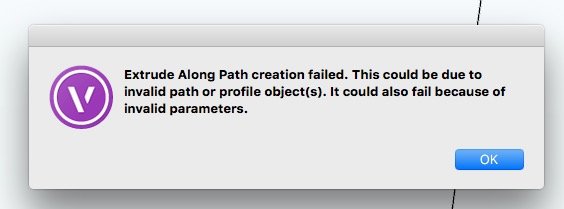
Here you go - You'll notice that it contains some symbols, and might suspect these to be the problem, but I've tried converting them to regular solids and it doesn't solve the problem. I'm wondering whether this is in any way related to the problem I posted in another thread, about things in subtractions/additions moving location, because there seems to be a bit of that going on with this object. failed subtraction.vwx
-
Objects within solid additions/subtractions jumping location?
line-weight posted a question in Troubleshooting
Am I right to think that an object that's part of a solid subtraction or addition ought to have an absolute position, relative to the drawing origin? In other words, say I draw solid (A) and solid (B). I subtract solid (B) from solid (A), to create a new solid, (A-B). The void in solid (A-B) is obviously in the same position as where solid B was, before I performed the subtraction. Now I edit solid (A-B) - I go into it and move the location of solid (B), and then I exit it, and of course, the void in solid (A-B) has now moved. Now I go back into edit solid (A-B). I don't change anything, I just copy solid B. I exit solid (A-B), and I do a paste-in-place of the copy of solid B. That copy of solid B should appear exactly where the void is, right? And this logic ought to hold, however many solids I subtract and add to each other ..... right? But either I am losing my mind, or some solids I am constructing are not behaving like this. See for example the file attached to this post. It contains a solid subtraction. Edit the solid subtraction. Copy either of the two objects it's made up from, exit it, and do a paste-in-place. When I do this, the pasted-in-place object appears in an offset location. Firstly, can anyone replicate this, and secondly, why is this happening? origin test.vwx -
I'm having this problem with another solid now. This time, it's still unhappy even if I copy it into a fresh file. Any hints to troubleshoot what's causing the problem?
-
Creating solids from enclosing surfaces
line-weight replied to line-weight's question in Troubleshooting
It strikes me that what I really want to do is use a section surface like this to cut the solid: I have drawn that in 2d polys using working planes - there are 3 polygons each on a different plane but their edges meet. What I don't know is how to make them into something that I can use as a solid section. I can convert those polygons into NURBs curves or 3d polygons, but I can't then see how to compose them into one surface (the compose command doesn't do anything). The VW help page on Solid Sections is not very helpful - doesn't tell me anything about what kind of surfaces I can use, whether they can be made up of multiple planes, etc.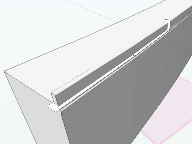
-
Creating solids from enclosing surfaces
line-weight replied to line-weight's question in Troubleshooting
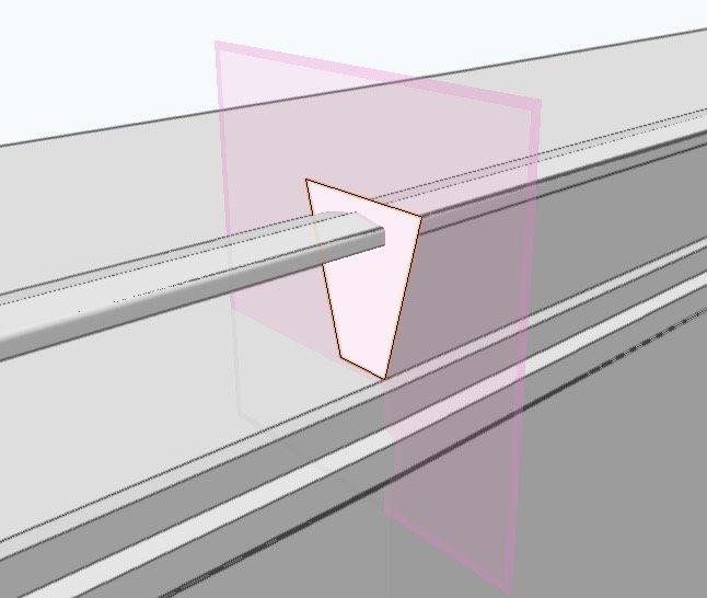
Thanks for the response @Pat Stanford So, I managed to get the solid I wanted in my first post. In fact, it seems possible to do it slightly differently than your suggestion: I can extract a surface from each side; VW will not let me use the loft command on these but if I convert them to 3d polys, then back to NURBs (why is this?), then it will, and I can use the "no rail" mode. This gives me a solid that I can subtract, which cleanly removes a section of the wall, but not the parapet. So I can get this far: But you have lost me a bit in the second part of your description - what do you mean I should use to do the solid section - this needs to be a surface, no? What I tried was to set the working plane to the "cut end" of the wall, and draw a 2d polygon: Converting this to NURBs gave me something that the solid section command would not let me use, but converting it to a 3d polygon worked. One thing I am unclear about - what's the difference between a NURBs surface and a NURBs curve, and what's the proper way to convert one to the other?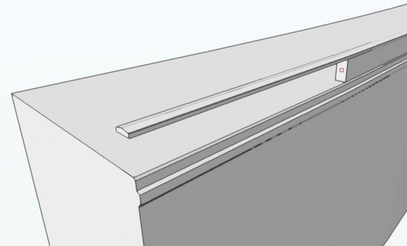

-
Creating solids from enclosing surfaces
line-weight replied to line-weight's question in Troubleshooting
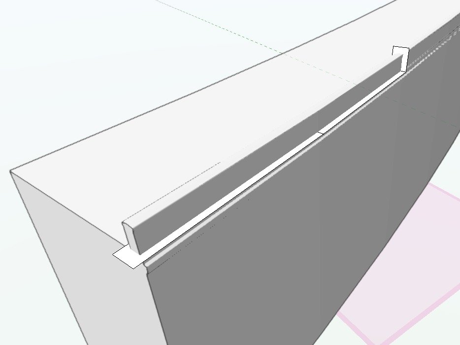
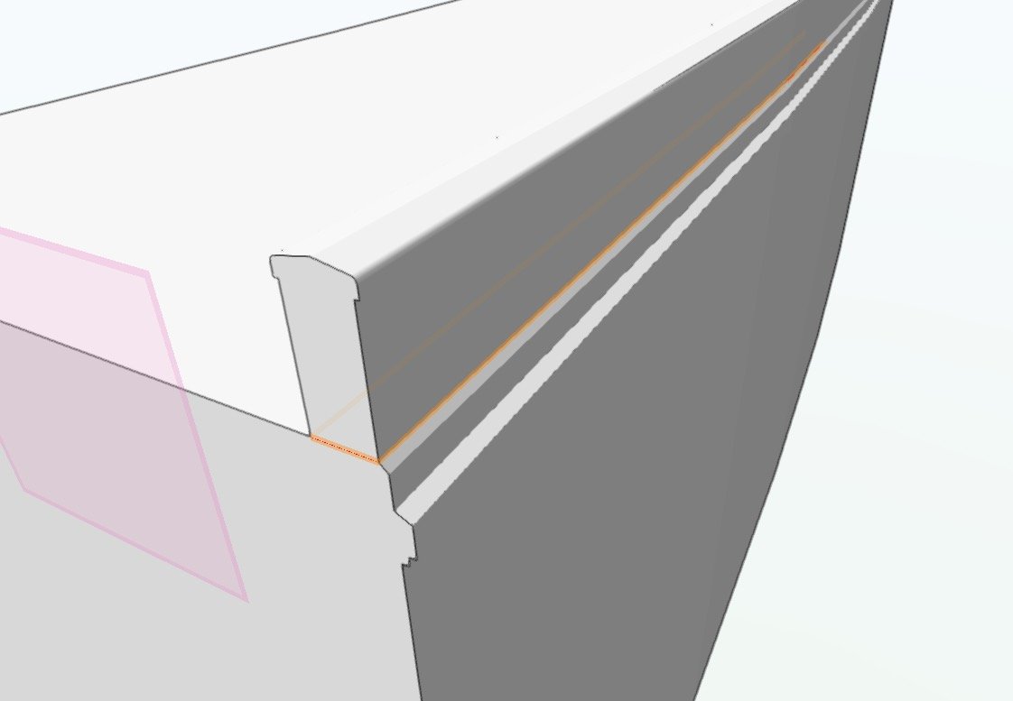
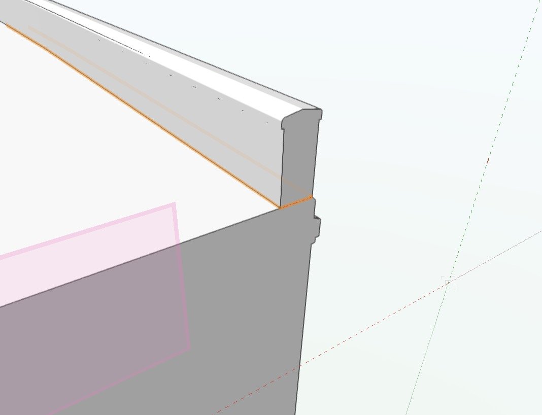
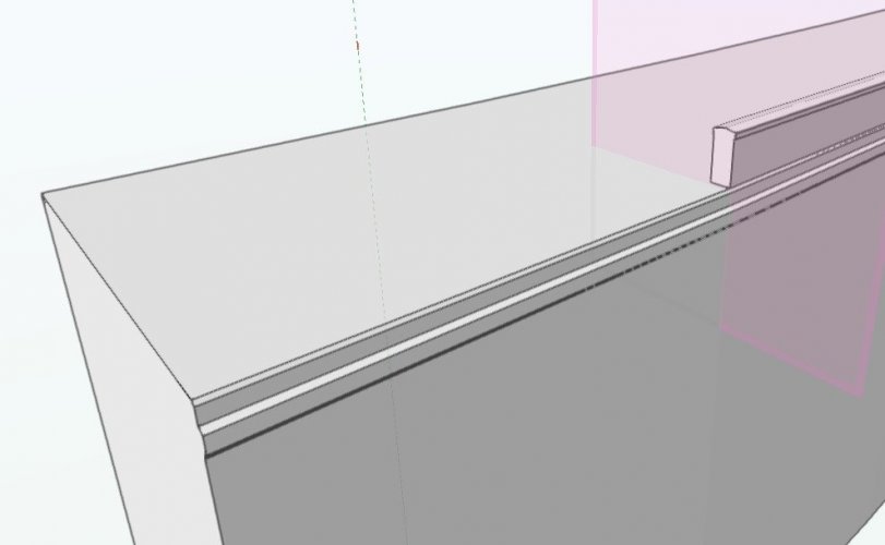
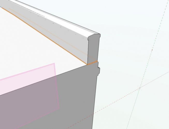
... perhaps I should add some context to this question. The solid I'm trying to create above, is one that I want to use to subtract from the larger solid shown in this post (and in teh attached file). Essentially I want to cleanly slice off a portion of the parapet wall, above the level of the highlighted red line. This seems very tricky to achieve. Doing a subtraction is one approach but there may be other better ones. You may need to look at the file itself to understand the geometry here as it's not as simple as it may appear (it's not just a straight extrusion). vsolid.vwx
-
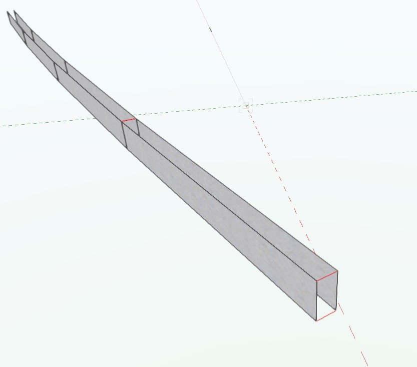
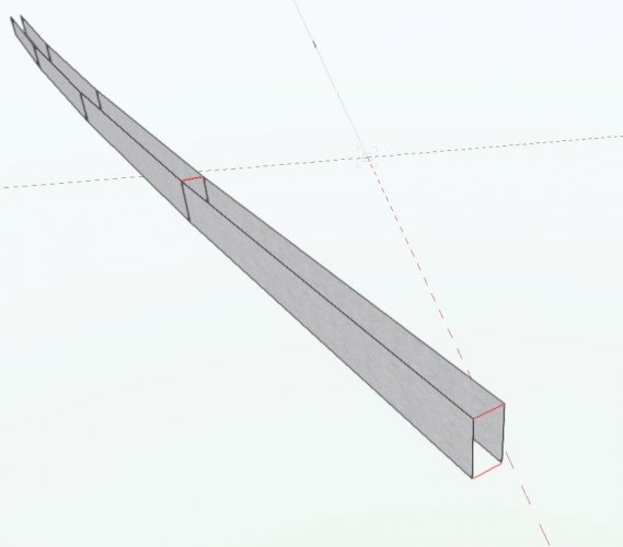
Never quite sure what the best way to approach this sort of thing is. In this case, I have 8 NURBS surfaces which I've extracted from an existing solid. 2 chains of 4 connected surfaces, and essentially I want to fill in the space between them to make a solid. (None of those surfaces are coplanar, nor are they rectangular) So, the red lines I've indicated would be some of the new edges on that solid. What's the most efficient way of doing this? surfaces.vwx
-
Advantage of "compose" over connect-combine is where you have a whole lot of segments you want to compose into one line: highlight them all, compose, job done (if it works). With connect-combine there would be quite a few more clicks.
-
Thanks! This is a tool I under-use. I'll make an effort to explore it some more as you suggest.
-
I often have trouble getting NURBS curves to compose with other objects such as lines. The VW documentation suggests that this is supposed to be possible - but is it? By way of example the attached file has two NURBS curves which I'd like to compose together with a line that joins their endpoints, but I can't make it work. compose.vwx
-
Scale / Fixed position not proportional - yes I 've read instructions
line-weight replied to DSmith2300's question in Troubleshooting
Another thing I didn't know until just now! -
yes - this is in 2018. There aren't any fillets or chamfers, no. The symbol consists of two solids: an extrude, and a tapered extrude. Subtracted from this symbol is an addition of two extrudes. It is in fact possible to subtract solids from a 3d Symbol - this was somewhat to my surprise.
-
What causes this? I have one file where a particular solid fails to regenerate each time I need to recover it from a backup. I can copy and paste this solid from an earlier version of the file - and pastes in fine - it's there and correct, but if I try to do anything to it, even just double-clicking into the subtraction without changing anything, I can't then exit it without it failing. If I copy and paste this same object into a blank file, there doesn't seem to be a problem. There only seems to be a problem when I put this particular object in a particular file. Is there any way I can fix this? Does it indicate a corruption in the file that I should be worried about? It's a subtraction where some simple solids are subtracted from a 3d symbol.
-
Scale / Fixed position not proportional - yes I 've read instructions
line-weight replied to DSmith2300's question in Troubleshooting
Doesn't help the OP - but I didn't know until now that this was possible - thanks! -
Viewports need to be linkable to DL cameras
line-weight replied to Andy Broomell's question in Wishlist - Feature and Content Requests
Seeing as this was raised, and a wish filed, nearly four years ago (if not earlier) and nothing has been done about it, I don't have much hope for anything happening in the next four years. As @grant_PD says - surely this does not need to be complicated? Thank you nonetheless for taking the time to write it up again @Andy Broomell -
Can a script change viewport class/layer visibilities?
line-weight replied to line-weight's topic in Vectorscript
Amazing! Thanks! If only the main bit of Vectorworks worked like this. -
Can a script change viewport class/layer visibilities?
line-weight replied to line-weight's topic in Vectorscript
Yes, this script is great and is saving me a lot of time and tedium on one particular project where I have a large number of viewports with quite complicated class setups. The eyedropper tool can be slow, not just because you have to go around each viewport manually, but because of the slowness with which Vectorworks opens up and draws sheet layers with large numbers of viewports (something that might have improved somewhat in later versions, but at least in VW2018 which I'm still using, switching between such sheet layers is incredibly lethargic and tedious). Being able to tick the box that re-renders all the viewports you've just updated also saves quite a lot of time (although, if I had one further suggestion to @Jesse Cogswell it would be that this box should be un-ticked rather than ticked by default, as it's quite easy to unintentionally set VW off on a redraw when you didn't meant to). -
I think I can spot a few radishes and tomatoes which have intersected with their crates....
-
@Kevin C all my working elevations/sections are produced using hidden line rather than OpenGL. Is there a reason you're not using hidden line? Because that *is* vector based. There are problems with hidden line... but I just about get things to a good enough standard for working drawings. I generally don't use hatches at all (except for section cut plane) and I also generally stick to black and white only. Traditional style pure line drawings.
-
Could it somehow be a result of the windows being inside-out on the upper floor (ie. they are in a wall which is drawn the wrong way around)?
-
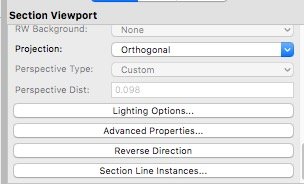
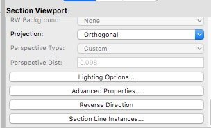
You don't need to manually rotate the section lines - you can just reverse their direction using the "reverse direction" button in the OIP for the section viewport.
-
I usually set up a sheet layer that is purely for the control of section lines - on there I have a plan (for vertical sections) and an elevation (for horizontal sections), and those two viewports I give easily recognisable names, then I use the "section line instances" control to make all section lines show on these viewports. Then I can move them around as I will, line them up with each other and so on.
-
@Tom W. it would be interesting if you could report back on whether the stacked-VP approach seems to work for you once you employ it on working drawings. There will be a few things that it will make a bit tedious (for example if you want to change the location of your section cut, you'll need to move the section line 3 times over, to the exact same new location) and there are a few things where I'm not sure if you'll hit problems or not. For example, what happens with things like grid lines. And automatic drawing co-ordination. My experience is that stacked viewports can be ok for mainly presentation stage drawings, because you kind of just need to get everything looking as you want it, and then freeze it like that and job done. However, with working drawings which you might be making constant adjustments and re-issues, it can spin things into a complex drawing-admin nightmare.