


line-weight
-
Posts
3,744 -
Joined
-
Last visited
Content Type
Profiles
Forums
Events
Articles
Marionette
Store
Posts posted by line-weight
-
-
Is the "structural member" tool now reliable and free of bugs?
Last time I tried using it, it certainly wasn't.
I currently draw all my structural members, and any wall studs, manually from scratch as extrudes.
-
27 minutes ago, zoomer said:
Well, for multicore CPU Rendering which has to run via Rosetta,
the Trash Can is still a tick faster.
But not for native Apps like Cinebench R23 running natively.
I think for anything else, single threaded or GPU related,
M1 feels much more snappier and even faster when running
via Rosetta.
That's certainly interesting to hear ... it seems I could be confident that it would outperform my refurbed 5,1 classic Mac Pro, where I'm trying to decide if it's worth upgrading the GPU to make it last another year or so before becoming entirely obsolete. The price of a new M1 mini does not make the price of buying a new video card for the Mac Pro look like very good value.
-
On 1/23/2021 at 12:14 PM, zoomer said:
Meanwhile I switched completely from Trash Can to M1 Mini
and am pretty happy with it.
Does this mean you are getting better performance overall from a base-specification M1 mini, than you were from a trash-can mac-pro?
-
This really, really should not be necessary though. 4 different stair tools, all of which have different problems or limitations. Sort it out, VW!
-
 2
2
-
-
17 hours ago, Tom W. said:
The Simple Stair when ungrouped is an Extrude
Thanks - did not know that! For whatever reason that tool is not in my workspace but I've just added it.
Having just had a look at it I can see that yes it does produce extrudes, which is loads more useful than the other stair tool. Looks like it can't do winders... but better than nothing.
-
21 hours ago, hollister design Studio said:
Hmm... is there a way to combine meshes and/or 3D polygons into generic solids?
I have noticed when architects send me sketchup models they are basically an un-editable mess of meshes...
There are ways but my experience of doing it to stairs objects is that it's immensely time consuming because you have to do a lot of ungrouping and then repetitive stuff like you have to do each step independently (as far as I recall).
I hardly ever use VW stairs now, for these reasons. Unless you are doing a really bog standard stair, it's quicker to model the whole thing directly from scratch.
Why the stair tool outputs something made up of polygons instead of solids I really don't know. I though VW was supposed to be a solids modelling programme. Why design it like that?
-
The X Y and Z could, alternatively, be colour coded in the dialogue box to match the axes on screen.
I'd like this for the "move" command as well. I'm forever doing that by trial and error.
-
1
-
-
23 minutes ago, Tamsin Slatter said:
Remember also that you can use a parametric tool to do most of the modelling for you, then, in a 3D view, ungroup it. This will give you the 3D geometry which you can then manipulate further using the 3D modelling tools.
Not very easily though, because it gives you a bunch of meshes and 3d polygons rather than solid objects.
-
Hm. Let's hope that these issues can be fixed, then.
It'll be interesting to see whether the higher spec mac minis when they announce them (later this year?) offer anything different in terms of peripherals.
-
Do you just use 1 monitor @zoomer?
I am quite interested in the new mini but I like to run 3 monitors. I know it's not supposed to manage more than 2 but it seems some people have got 3 working by various means.
-
I name all my classes with a * prefix - this way, all of VW's auto created classes go to the bottom of the list and I try and just ignore them. At some point I decided that's easier than trying to track them all down, and it doesn't generally seem to cause problems.
-
1
-
-
I generally find that once a slab starts refusing to be edited, it is likely to do a disappearing act some time soon.
My solution
- only use slabs when there's a major benefit over other more reliable objects
- if one starts being troublesome or disappears... go back through backups, find a version where it still seems to be ok, copy and paste that back into the file.
Alongside the automatic backups, I tend to make a separate "safe save" of any important VW projects I'm working on every day or two... these are often useful to go in and retrieve non-corrupted earlier versions of objects.
Not ideal. But maybe they'll get around to fixing it within our lifetimes - we'll see.
-
1
-
-
32 minutes ago, Matt Hall said:
2021 document. slabs are disappearing. while trying to edit them. I have redrawn them several times from scratch, any updates with this bug.
Let's not get impatient... they've only had 5 years to fix it.
-
1
-
-
4 hours ago, axhake said:
Looks like you are getting into this now.
"am I right in saying that all of those NURBS parts I've drawn are not necessarily exactly parallel?"
They should be, there are two ways to check this:
a) Copy your profiles and paths and change one end profile to a NURBS, then select that profile and one of the paths, using "Extrude along a path" create the extrude. Now go to the other end, switch to Wireframe and see if the extrude aligns with your end profile. If you have accurately placed your start and end profiles it will align, if not they wont.
This applies if I use the "true curve" rather than the faceted version for the path, right?
Because, once it's been converted to a segmented version, the end profiles are no longer perpendicular to the end segments of the path.
This started me thinking... is there a way to facet the path such that the end profiles *are* perpendicular to the end segments?
If there is, could this mean that each section of the wall/viaduct could be constructed from an EAP rather than a lofted object? The advantage of this would be that having constructed your wall/viaduct, you could make alterations to the profile without having to rebuild everything including the path.
As far as faceting the curve is concerned, I am thinking along these lines:
I have just shown a circle quadrant rather than a NURBS curve, for simplicity, but I think the principle would be the same (?)
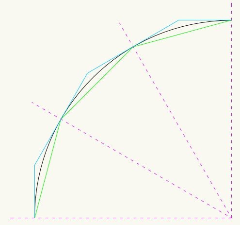
Black is original "true" curve, green is the method of faceting used by the current script, blue is an alternative, which means that the end facets would be at right angles to the true curve at its endpoints.
I expect there is some reason this wouldn't work!
-
31 minutes ago, axhake said:
"I have been too lazy to try this for myself out before typing this post... but suspect it's something you've already gone into"
Over several months I think I have a flat spot on the side of my head where I have been hitting it against a wall figuring this out and coming up with a workflow that works.
It seems to me that what you have come up with works as well as is possible within VW's limits and is a method that will be very useful to anyone trying to deal with this kind of geometry. I hope that some people at VW will take the time to go through it and understand it fully, most crucially understanding the problems that it solves.
I think the principle of making things "exactly correct" at the control profile locations is sound. And then what happens in between them is 99.9% correct but most importantly does not create the horrible buckled, messy geometry that you highlight in your examples of why the seemingly most obvious approaches don't work.
In my particular use case for this... the biggest test would be using it to try and create a junction between two converging viaducts. When they are only curving in plan, it's quite straightforward to see how to do this, but my brain starts to hurt when I try and think about the geometry if there are also curves in elevation. I'd be interested to see if you've managed to do something along those lines...but that perhaps should be a separate discussion.
In any case thanks very much for your work on this!
-
1
-
-
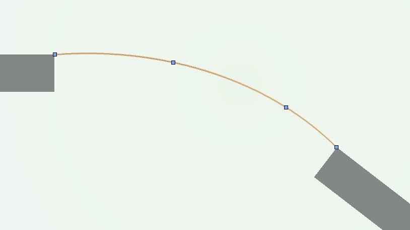
My next question is about drawing a NURBS path where it needs to transition from a straight line (or even a radiused curve). For example, let's say this is plan view, and the grey rectangles represent straight sections of wall, or viaduct, or whatever. I want to create a curved connecting section using a NURBS path.
Drawing it in "interpolation point mode" doesn't work because (I think) there's no way to ensure that the ends of the NURBS curve are exactly square to the ends of the straight sections:
However it can be done in "control point mode":
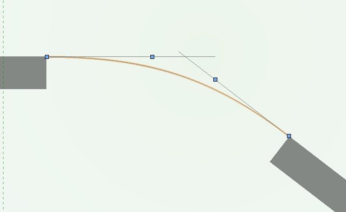
If I then place a profile at each end of that NURBS curve ... how do I then find all the "parallel" curves? Because I have to draw them in interpolation mode. I'm not going to get the correct result by trying to draw an interpolated curve between two points. So I can split the curve and introduce a third profile in the middle somewhere. Will that give me a correct curve? Or is it a case of the "parallel curves" becoming more and more correct, the more intermediate profiles I introduce?
I have been too lazy to try this for myself out before typing this post... but suspect it's something you've already gone into.
-
Thanks. I guess that's what I'd 'intuitively' expect - that the more control profiles, the more accuracy.
Do you feel you understand sufficiently the maths behind the way NURBS curves are constructed, to say that in theory (assuming all the profiles are perpendicular etc) the NURBS should all be exactly parallel?
-
There's a question that this method raises for me:
- I draw a NURBS path, through each of the control points I want
- assume the profile, set perpendicular to the path, at each control, is exactly the same at each of those points
- then I draw all of my other NURBS paths, using the vertices of the control profiles along the way
- am I right in saying that all of those NURBS parts I've drawn are not necessarily exactly parallel?
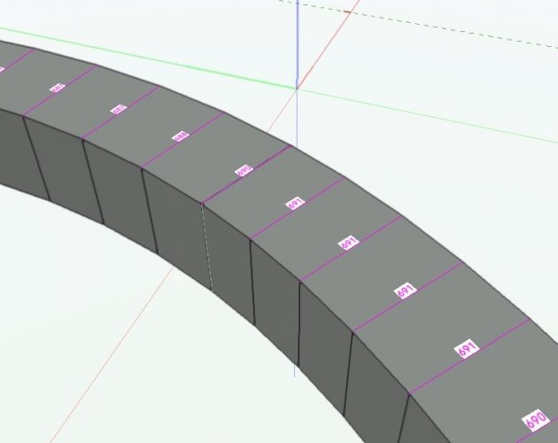
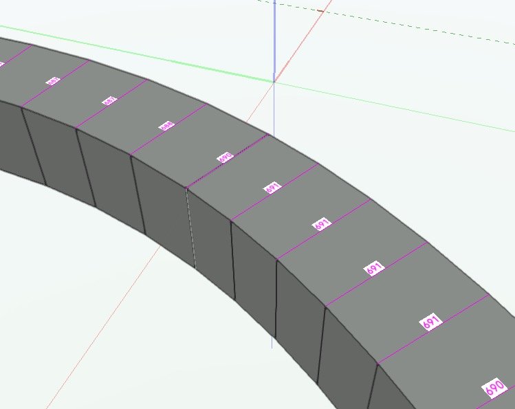
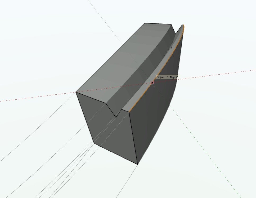
To test this I've made a very simple example... the profile is exactly square, 690 by 690. There's just a start profile, an end profile and a mid profile. It's curved in plan only. I've constructed the 'wall' using the method described. If I measure the width of that wall at each of the profiles, it's 690 as expected. But if I measure its width between each of the segment vertices (which ought to be at positions exactly on the 'generating' NURBS curves) then it varies very slightly... in this example between 687 and 691.
Is that just an inevitable result of the way VW produces the NURBS curves?
I expect that this is something which in practice usually wouldn't matter... but it might in certain use cases, and maybe it would become more marked with more complicated curves.
I can see that maybe you could try generating the extra NURBS curves by doing them as a parallel offset from the originating one...would that work? I think it might when they are on a 2d plane but then things would get complicated in 3d.
-
In the meantime though - I've successfully built one of the sections and it looks good - nice clean geometry.
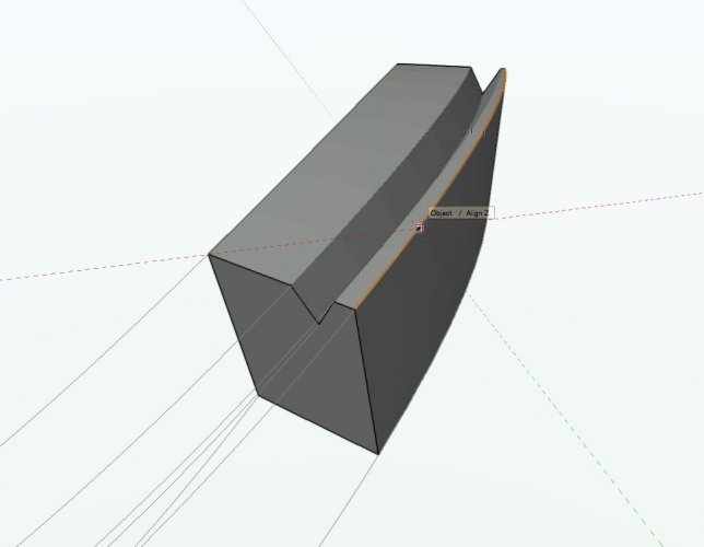
Going to mess with things a bit now and try it on some different profiles.
Your step 6 can be simplified a little, I think. Instead of creating 7 individual lofts - it seems to work to select all 7 lines as 'rails' in sequence - and then tick the "ruled" box as well as the others (this makes it join them with straight lines instead of a crazy loopy one) and then you can do the whole lot on one go. Unfortunately, it doesn't make a solid with end caps on - you still have to add these as you describe.
-
I'm not managing to get the Marionette network to work - if I drop it in the file and press "run" or "select curves..." nothing happens. I've successfully converted to a menu command but choosing the menu command doesn't result in anything happening. It might be a result of it being converted to 2018?
I do get this message when I copy the network into the file
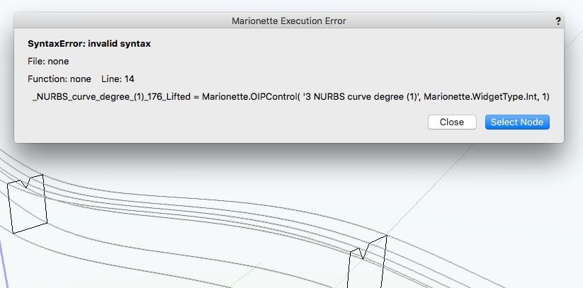
Not to worry though - I will continue through the steps using the nurbs-segmenting command I already had from before.
-
17 minutes ago, axhake said:
Hi @line-weight, hopefully this will show you how to get things aligned.
Thanks! That all makes sense.
Having understood your method, I can suggest a slightly different way, which avoids having to split the NURBS curve:
1) Activate working plane tool, planar face mode
2) Click on arbitrary point along NURBS curve to establish working plane perpendicular to curve at that point
3) Place a 3d locus at that point (ie where working plane and NURBS intersect
4) Select the locus > move 3D and make sure "cartesian" rather than "working plane" is ticked, and move the locus some distance along 'Z'
5) Now use that 3d locus as the reference point to rotate the working plane, in the same way you used the line drawn on the layer plane.
-
Apologies to @axhake for taking so long to respond to this. I've finally found the time to sit down and look at it properly. As I'm still an upgrade refusenik, and using vw2018 I'm not able to open the attached files but that's fine, I think it would be good for me to test the method drawing somethig from scratch myself.
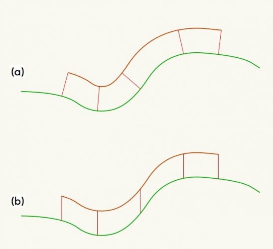
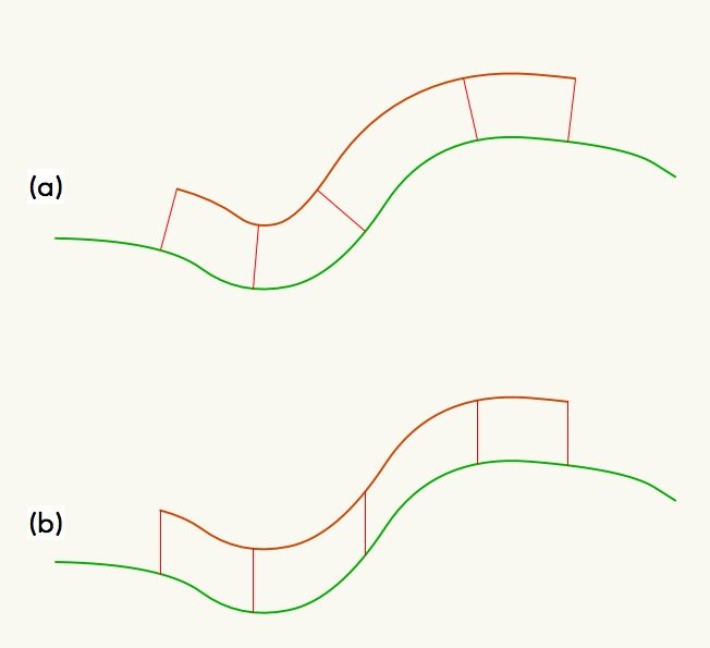
The first thing to get right is the placement of the "control profiles". @axhake you say you have placed them "vertical and square to each of the control points". It strikes me that there are two ways that you might want to place these, if you are building a wall-like object that is curved both in plan and elevation:
(a) The profiles are placed perpendicular to the path in plan and perpendicular to the path in elevation and and perpendicular to the horizon along the axis of the path
(b) The profiles are placed perpendicular to the path in plan and perpendicular to the horizon in elevation and and perpendicular to the horizon along the axis of the path
The diagram below shows what each looks like in elevation (for now ignoring any curve in plan) - think of the green line as a ground surface and the brown line the top of a wall built up from that surface. The red lines indicate the orientation of a constant-sized control profile in each case.
I think I'd like to test this method for each scenario.
My first question - what's the best way to get those profiles into location for each wall type? The first hurdle I've come to is a rather basic one: I can't work out how to generate a line that is perpendicular to a 3d NURBS curve in plan. This is easy with, say, a circle - if you draw a line starting at that circle, then one of the snap constraints you are offered is "perpendicular". This doesn't work with a NURBS curve though - am I missing something?
I've discovered that you can get a 3d working plane that's perpendicular to the NURBS curve simply by using the Planar Face Mode and clicking on a point on the curve. The problem with this is that it has no regard for the horizon and it rotates as you go along the curve. Is there a quick and easy way to establish this working plane and then (for wall type a) tell it to rotate so its X axis is horizontal or (for wall type b) rotate so its X axis is horizontal and its Y axis is fully vertical?
-
Enscape no good for those of us on Mac, unfortunately.
-
3
-
-
I think when I looked, you can still download it for free as long as you don't use it for commercial work.


Framing take-off
in Architecture
Posted
My feeling is that while all these ideas for automatically framing around windows and that sort of thing would be really great if it could be made to work.... it's way down the line of things that need to be urgently fixed. Make the windows themselves work properly first, for example. Because if the windows are essentially unusable at a construction detail level, then there's not much point trying to make the walls able to frame around them.
And while it would be great for VW to automatically create correct corner junction details in timber frame... can we first get it to work properly with basic monolithic materials like masonry, please.
As pointed out above, timber frame corners are not usually mitred in real world construction.... but neither are brick wall corners, whatever VW thinks.