line-weight
-
Posts
3,746 -
Joined
-
Last visited
Content Type
Profiles
Forums
Events
Articles
Marionette
Store
Everything posted by line-weight
-
Could save yourself one step by making the crop object itself of the lineweight/type that you want to indicate the outline, and ticking "crop visible" in the viewport OIP? (would save duplicating it in annotations I think) I'm forever changing my mind about the best way to clearly draw the "section cut" line for interior elevations. It can be difficult to do it in a neat way when the section is complex, and if you use the crop object you have to keep an eye out for when it needs updating to match changes in the model geometry. The drawings I'm currently working on I've decided to do it by using a solid black fill, merged, for sectioned geometry: Still not entirely happy with how this looks, graphically.
-
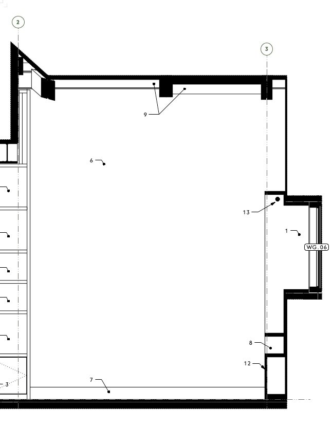
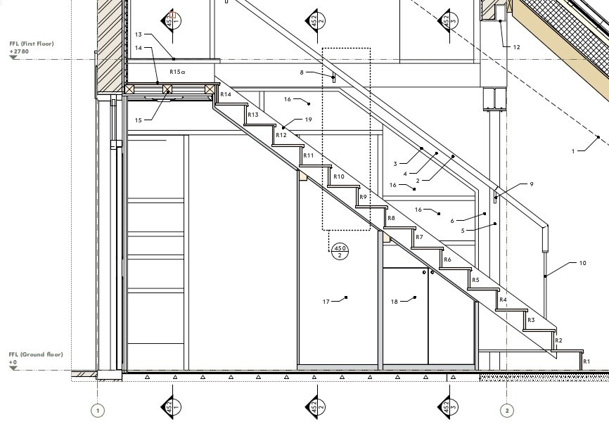
 There are many occasions where it would be very useful to have a fully co-ordinated section line instance show up on another section viewport. For example here is a plan view of a staircase Marked on there are three sections (numbered 452/1, 452/2 and 452/3). These are fully co-ordinated with the section viewports they are associated with - if I want to move the location of a section cut, then the section line instance on this viewport will move accordingly. But I want to show these three cross-sections on the long section through the stairs too: In this viewport, those section lines have to be placed manually. They are co-ordinated with the relevant section viewports only to the extent that the viewport/sheet numbers will update with any changes - if I change the location of any of these sections I have to remember to come back to this viewport and move the section lines manually.
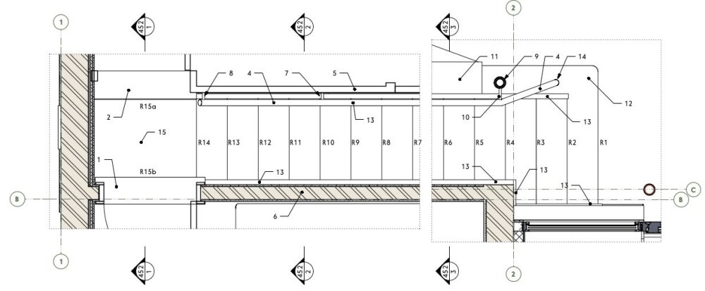
-
I currently make my interior elevations using regular sections (because of the silly thing where you have to put interior elevation markers on the design layer instead of in annotations like everything else). Where the ceiling is anything other than dead flat It usually involves some very careful placing of the section cut line, and/or some fiddly cropping of the viewport. The trickiness arises anywhere the section cut line cuts the ceiling in a location where the ceiling is lower than it is next to the wall you want an elevation of, because the top bit of the wall then gets obscured. It isn't always possible to move the section line right up against the wall because it'll then cut through anything projecting from the wall (for example shelving) that you want to show in elevation. This problem comes up when the ceiling has dropped sections, or when it's a sloping ceiling. This is parallel to a problem creating reflected ceiling plans, which is discussed here: https://forum.vectorworks.net/index.php?/topic/66836-reflected-ceiling-plan-work-flow/&do=findComment&comment=499500
-
Grid Tool visible in 3D Viewports
line-weight replied to Hamo's question in Wishlist - Feature and Content Requests
As far as I can see, it already is. If I create a "top" rather than "top/plan" viewport, in orthogonal projection, the grid lines show. Works in both shaded and hidden line. -
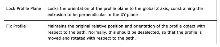
@symo the EAP tool can be quite infuriating, because when it fails it doesn't generally tell you what has gone wrong. The VW documentation for it is rather poor: https://app-help.vectorworks.net/2024/eng/VW2024_Guide/Shapes2/Extrude_along_path.htm In particular it's very confusing to understand what those two tick boxes in the dialogue do @markdd's video shows that you should tick the "fix profile" one. In the explanation above, what exactly does "the profile is moved and rotated with respect to the path" mean? There needs to be some clear graphical explanation of exactly what these tick boxes do. They are only very briefly mentioned at the very end of the video on that page but they are quite critical to whether the operation produces the intended result. I'm going to tag @Kristin Bailey here because she responded proactively to another thread about help documentation. I've complained before about the EAP help page but with no response. Going back to what was happening to your attempt, I think it was failing because without selecting that tick box, it'll try and run the "profile" along the "path" using the centroid of the "profile" as the point that intersects with the path. This produces self-intersecting geometry, which the EAP tool doesn't like.
-
Rendering differences in VW2023 on Windows and VW2024 on Mac
line-weight replied to MGuilfoile's question in Troubleshooting
I find that I can end up with different colour results, depending on whether I use "publish" or use "print" and then save as PDF. (I'm a mac user) In the latter case, I think the colour management somehow gets done differently because it's handled by macos instead of VW (or something). This has caused me problems in the past. It's annoying to have to use the "print" method to get the correct colour output because of course if you want to export a whole load of sheets at the same time it takes a lot longer. I'd be interested to see if you notice a difference doing this. It's something I've mentioned in the past but never seems to get much interest. -
Rendering differences in VW2023 on Windows and VW2024 on Mac
line-weight replied to MGuilfoile's question in Troubleshooting
When you say "renders the images much darker" do you mean that when you export to pdf, the images come out darker? -
yes agreed this is an option. In fact this is how I've tended to deal with legends until now too (yet to decide whether to transition to Graphic Legends) As you say, hazards include text getting cropped out unintentionally. And lack of flexibility about things like text column width across different sheets. But really ... all that needs to happen is for the "general Notes" object to have an option not to number the list of items. Maybe I should do this as a wishlist item.
-
@Matt Panzer getting this to work has reminded me of another issue related to section viewports. Grid line objects get drawn as a solid line "in elevation" (as well as existing in the annotations space) if they are seen by the "below cut plane" extents of the section. I think I've noticed this previously in HSVPs and for that reason place my grid line objects at an elevation well above the model. That means that normal downwards-looking HSVPs don't see them and the issue doesn't arise. However... in these reversed ones, they *are* now seen, and unless I exclude them by setting the "below cut plane" extents to a suitable limit, they get drawn as solid lines in the viewport (superimposed on the dashed lines they are intended to display with, in annotations space. Not sure if this is a bug, or me doing something wrong.
-
Yup sure, got that - it's just that that particular number no longer refers to an absolute-value elevation, as it does normally.
-
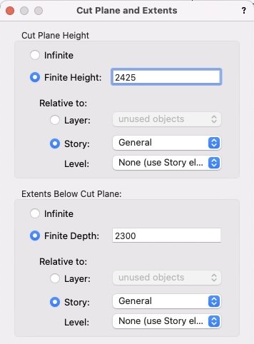
One thing that becomes confusing is the meaning of the "Finite Depth" number for the viewport's Cut plane and extents. In the example above, the cut plane is set at 2425mm above my datum. If I want to show everything (looking upwards) within 125mm of that cut plane, then I don't set the "finite depth" field to 2425+125=2550 (it won't let me set a number higher than 2425 here), instead I seem to need to set it to 2425-125=2300, as shown in the screenshot above. So, that number no longer represents an elevation above datum (like it does in a regular HSVP).
-
Worksheet stripe rows - alternate colours
line-weight replied to Flair-Studio's question in Wishlist - Feature and Content Requests
You can give rows a background fill - highlight whole row, then format cells Still rather tedious, but better than drawing rectangles.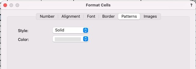
-
By the way: this would be useful in non horizontal sections too. Sometimes I come across similar issues with interior elevations, for example, which I make using sections. Generally you want a section taken as close as possible to a wall face but you often end up with choosing between slicing things you want in elevation, or having bits of the wall face obscured by sliced bits of sloping roof, etc.
-
The reason it would be handy is that commonly you might have a regular HSVP set up with the crop and annotations and visibilities and page position that you want, and if you could simply duplicate this and then flip it to an RCP, that would save a lot of repeated work getting the layout set up. It would be good though if it worked better than the "reverse direction" button for regular section viewports - which reverses the section direction but doesn't mirror the crop and annotations, so you end up having to fix all that manually.
-
I also feel that occsaionally snaps get turned on or off without me intentionally doing anything.
-
Interesting. I have just tried this and at first sight it seems to work perfectly. (It would be great if there could be a button on the OIP of any HSVP that would do this in one button press - reverse the direction and flip to a reflection) And the trick of per-object cut plane overrides still seems to work. Now I just have to decide whether I dare use this in some actual production drawings. But the combination of tips in your last few posts has made me feel a bit less despairing about embarking on doing the RCPs for this job, so thank you very much!
-
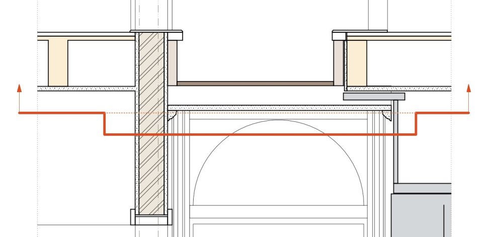
However - I did just try this, and it actually does work for one specific case in my example: The thick red line is where I want the section plane for my RCP to go ... and the stepped-down section is because otherwise, annoyingly it slices through some decorative coving on a section of dropped-down ceiling (that is, on the dotted orange line), and I'd like my RCP to look at that coving in elevation. Using your suggested trick I could select that coving object and tell it to drop the cut plane just for that object, and it did the job. (After a bit of confusion due to the coving object being within a group - looks like I have to apply the override to the group and the sub-object for it to work) This kind of cheat will happen to work in some instances and not others ... but is a good one to have up my sleeve - thanks.
-
@Matt Panzer is there any prospect in the near future of the "extents above cut plane" being made to work the same as "extents below cut plane" - that is, where I don't have to define/over-ride it for every single class, as described in my previous posts on this thread? I think I remember discussing this more with a focus on the scenario where you might want to show overhead geometry in dashed lines, on a regular HSVP floor plan - but particularly in the case of generating reflected ceiling plans, changing this would make a big difference in how painful it is.
-
That sounds interesting. How would that over-ride work? If I could draw a poly and say "drop the cut plane elevation by 300mm in this area" that would be very useful. Don't think I was aware of this. Will have to try it. But an over-ride applying per region would be more useful than per object I think.
-
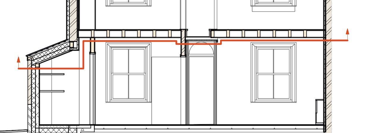
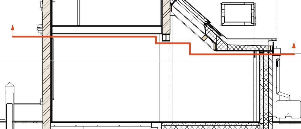
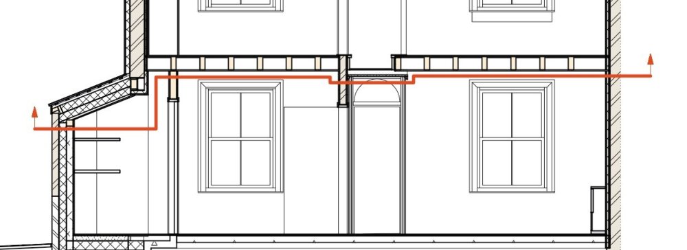
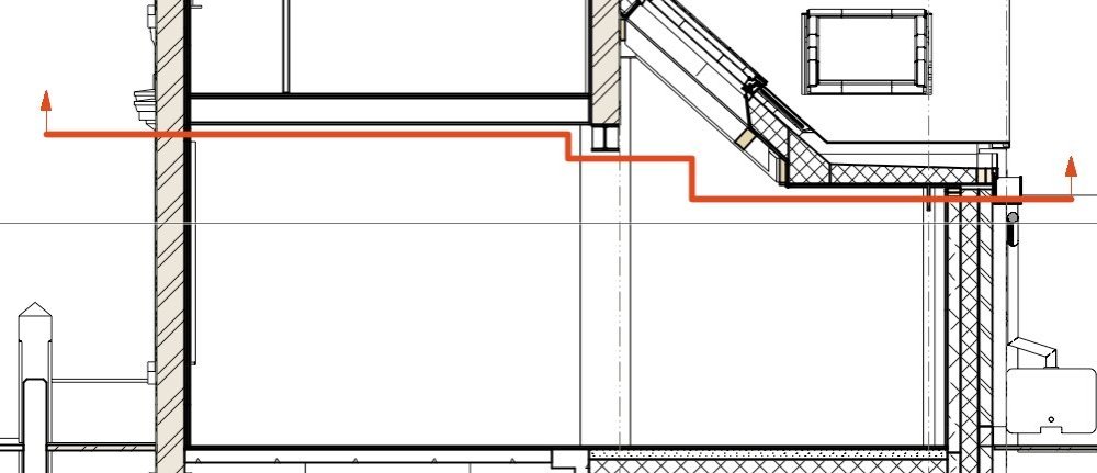
Eurghh. Back to fighting with RCPs again. If the problem I describe in the post above can be overcome, then it can perhaps work OK for certain types of buildings. But a lot of the buildings I work on, they have ceiling and floor heights that can be all over the place, and this means that it actually doesn't work very well just to cut a horizontal slice through the building, because then you have to choose what elevation the cut plane is at, and whatever you choose, it's going to end up slicing through stuff you don't want it to, in certain places. Really what you want is a kind of staggered section. For example, this building, here are two sections through the ground floor (at right angles to each other) and the red lines show where I'd ideally have the "section" cut for the Reflected Ceiling Plan. But this just isn't possible using horizontal section viewports. You can do a single (I think no more than a single?) stagger in a regular section viewport (ie a non-HSVP one). So you could cut a section viewport horizontally, and have a step in it ... and then mirror it. But I don't think it'll then give you gridlines for example, and the fact it's mirrored is probably going to cause weird problems. In any case, as illustrated above, you might want multiple steps, in both directions. Other strategies involve a patchwork of carefully cropped HSVPs, each of which can be at a different level. That gets messy too. Starting to wonder whether it's easiest just to take a very basic horizontal section and pretty much draw my Reflected Ceiling Plans manually in the annotation space, in many cases. Perhaps switching "extents above cut plane" on and off temporarily to trace it. I wonder if any other software deals with this better. It's rather tricky to get something that replicates a manually drawn RCP because they tend to involve a certain level of abstraction in practice.
-
Does your 3d viewpoint seem to have any effect (ie. do the cursor cues start working again if you move away from the geometry - this is something I have realised happens)
-
@Gunther Has just been misbehaving for me. I did as you describe and yes, I could check/uncheck boxes. It was misbehaving while I was editing within a group on a design layer. Going to the Tools>Purge command caused something funny to happen - bits of a random sheet layer became visible superimposed on the 3d view of the design layer, and stayed like this when I exited the group. I had to close and re-open the file to get rid of this. All of this may be entirely unrelated to the missing cues issue of course. Regarding the missing cues - again, it seemed to be the case that moving my viewpoint (3d perspective) further away from the geometry let the cues re-appear.
-
Still has to be done manually as far as I'm aware.
-
Hyperlinks in Worksheets
line-weight replied to Taproot's question in Wishlist - Feature and Content Requests
Bump again. It's 2024. We really need to be able to provide weblinks in things like schedules. -
Although that would be useful in the long term, the General Notes object first needs to have the simple option of turning off the list numbering. Until that's possible, being able to style it wouldn't help. ...Unless you meant a style for callout objects? Yes it would be good to style callout objects. At present I "style" callout objects using dedicated classes which lets me set things like arrowheads. But it doesn't control all aspects.