line-weight
-
Posts
3,744 -
Joined
-
Last visited
Content Type
Profiles
Forums
Events
Articles
Marionette
Store
Everything posted by line-weight
-
 Yes I see. I'm wondering if I can actually do this by making non-hybrid symbols that simply contain a 3d element and a 2d element, but both within the 3d component, and then control which one is shown in any viewport by class. And perhaps use stacked viewports with one dedicated to electrical objects, as you propose. This reminds me I want to make a wishlist item for more granular control over 2d components in HSVPs. If they could be controlled per object or per object type a lot of these problems would go away.
 -
That in fact would deal with the "below a shelf" or "above the cut plane" issue. (how do you deal with that?) But it would still be the case that in any other viewports where I had 2d components switched on, the 3d geometry would disappear. I could deal with this by making a top view 2d component & controlling by class ( basically what you do) but I'd rather not have to do that if possible; it offends my principle of not drawing things manually that VW should be able to draw for me.
-
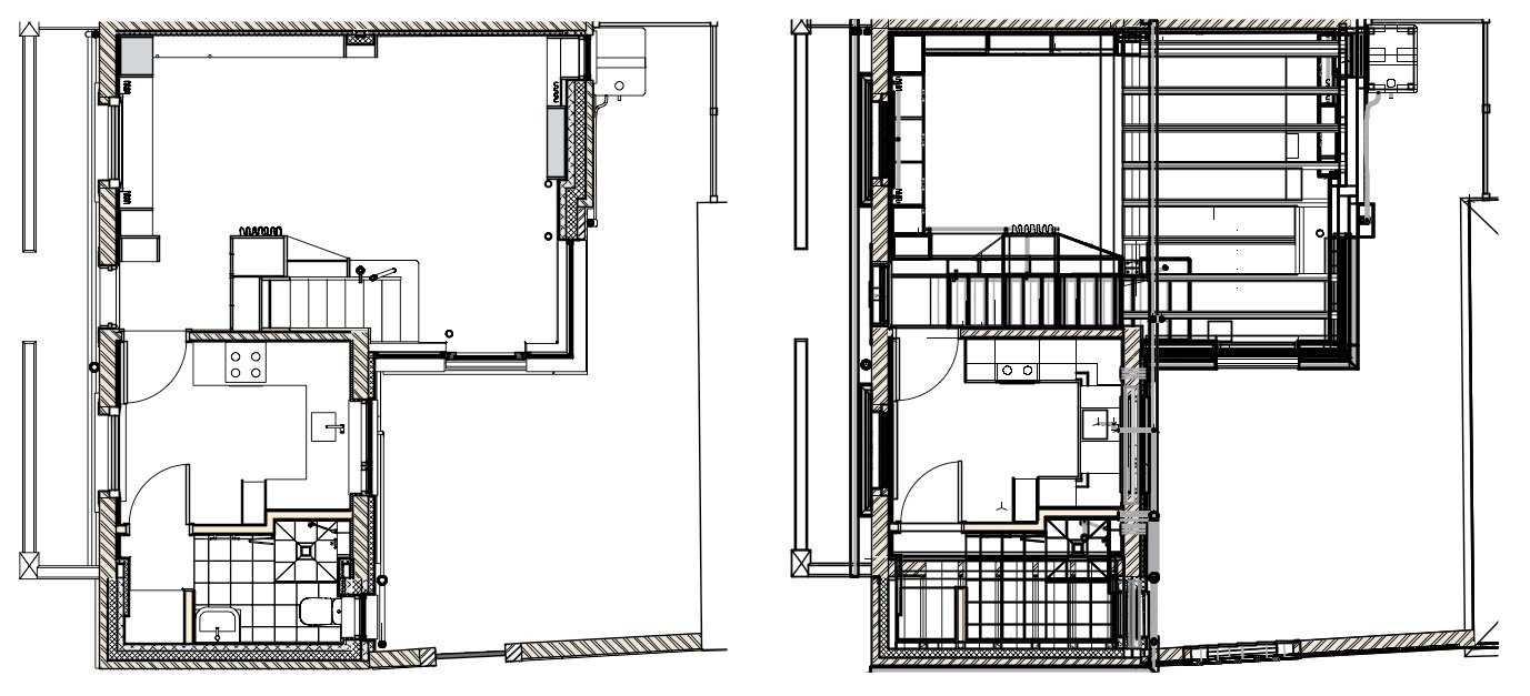
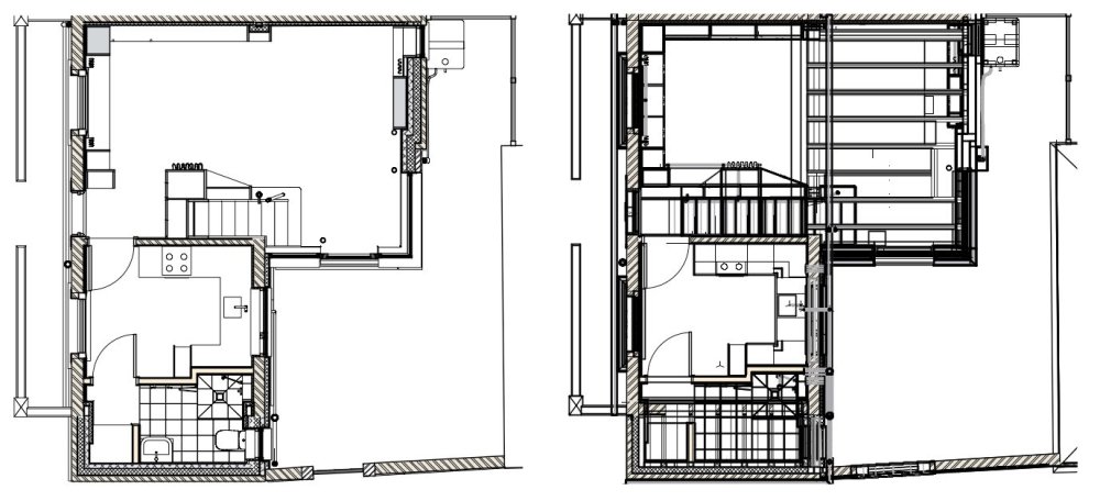
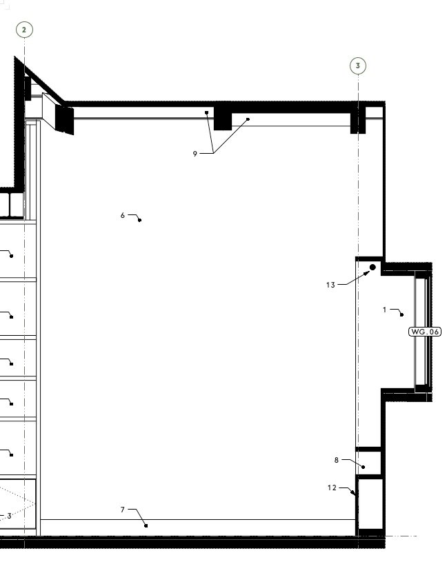
I think data tags would only be useful if I could put them in the annotation space of viewport sitting at the plan location of the object they were associated with, and have them attached in such a way that if I moved the object in the model, the tag would move as well. And if i deleted the object from the model, the tag would disappear from the viewport annotations, and so on. I'm not sure if this is actually possible. Otherwise, I might as well just use dumb 2d symbols in the annotation space, as I currently do. It does look like Top/Plan currently serves this kind of purpose better. However, once you're committed to an HSVP workflow, it changes how you draw the model. If I make a top/plan viewport of my model, it's a jumbled mess - on the left below is HSVP, on the right is what it looks like as top/plan. Neither has any annotation here. Of course with a lot of fiddling around it might be possible to sort the model out such that it would work in either view type, but the amount of work doing that & maintaining it would be completely disproportionate to the benefits (for me at least).
-
Would data tags somehow work for this? I've not used them much so far. My understanding is that they can only be attached to objects that are visible in a viewport - so would that mean I wouldn't be able to use them for things like those sockets hidden under shelves, or ceiling lights that are above the cut plane?
-
On re-reading @Tom W.'s description of his system, I realise that it is of course set up to work with top/plan viewports, and therefore doesn't easily translate to a horizontal section workflow. Another problem I've realised: As long as I get my 3d component and 2d component set up and working, I can choose per viewport which is going to display (by toggling the "display 2d components" tick-box on or off). So for wall elevations I switch that off (and the 3d object is drawn), and for electrical plans I switch it on (and the 2d symbol appears). However ... on general floorplans I do want 2d components of things like doors to appear but I don't want electrical symbols to appear, so there is a problem. I guess I can get rid of the electrical symbols by class, but having "display 2d components" on means that the electrical fittings' 3d geometry doesn't get drawn ... and there are cases where I will want that to be drawn. So it looks like hybrid symbols probably aren't going to work for me unfortunately.
-
Next issue... what if (say) it's a power outlet below a shelf? A normal floor plan (in my case a horizontal section viewport, not a top/plan viewport) won't see it if the cut plane is above the shelf. So it won't display the "top" 2d component. Well, I can include two 3d locii in the 3d component, one at floor level and the other at say 2m above floor level. Now VW registers the object as being 2m tall and "cut" by any cut plane within that 2m high zone. So I can put the 2d geometry in the "top (and bottom) cut" component instead of the "top" component. And this seems to work. If the socket itself is below the shelf then the 3d geometry is out of view, but if I have my HSVP set to display 2d components, that 2d component will appear drawn over the shelf, as I want it to. I guess something like this would also work for ceiling lights, which are going to be above the cut plane? I'd have to include a 3d locus at floor level, within the 3d component of the symbol.
-
Ok, so I'm having a go at setting up some hybrid symbols. The first issue I run into .... is it possible to have a 2d component which is set to "page units" and a 3d component set to "world units"? The 3d component needs to scale with the viewport scale obviously. But I'd rather the 2d component didn't. That is, if I have an electrical layout at 1:20 and another one at 1:50 I don't really want the 2d symbols to be different sizes on the page. Or is that something I just have to live with, using this method?
-
I had a similar problem to this, with keynote legends. I think in the end I worked out it was somehow related to odd line spacing in the text (or text style) used. Changing the line spacing seemed to sort it.
-
this thread mght be of use
-
Editing notes in "general notes" object: "edit" button calls up wrong note
line-weight replied to line-weight's question in Troubleshooting
I've just sent you a PM with a file. As mentioned in that message - I wonder if this behaviour is caused by several notes having the same "description". -
As per the title - press "edit notes" in the OIP of a general notes object; this brings up a dialogue called "general notes". Highlight one of the notes in the upper pane of that and press "edit" button below. This frequently brings up the text and description of some other note from the one you highlighted. Fairly sure that's not supposed to happen. It's quite dangerous as it provides a way to over-write an existing note without realising.
-
As my notes databases become larger and larger I become more and more nervous about accidentally messing them up and then not being able to revert to a previous version, as can easily be done with the automated backup of drawing files. Because of the clunky way the notes manager works (see complaints ad nauseum in other threads) it's rather easy to press the wrong button, or just "OK" when you didn't mean to, and realise you've unintentionally over-written or duplicated a note. There's no "undo" option, because changes to the notes database don't seem to count as actions in the drawing as far as undo history is concerned, and there's no auto-saved backup from 15 minutes ago to revert to if things have got confusing enough that it's easiest just to rewind back in time. I guess that there are various reasons this might not be totally straightforward to implement, because the version of the drawing file and the notes database might be out of sync... but I think something is needed.
-
Might be a job for symbols-within-symbols though, so that you could create variants that still referenced the same geometry where it didn't differ.
-
How would this work in a viewport context though... if you had two instances of the same symbol and you wanted one shown as the plastic variant and one as the stainless one, you wouldn't be able to control class visibilities per symbol instance, only per viewport (which would make all instances the same variant)....or would you?
-
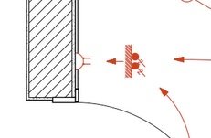
Cunning! If you have two items located one above the other - say a lightswitch that's directly above a power outlet - do you have a way of dealing with this so that the red symbols don't get superimposed on each other in plan? Edit - that's what's happening here, right?
-
This is great! I didn't expect my question to be answered so comprehensively!
-
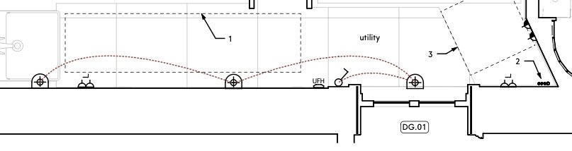
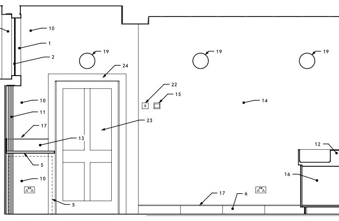
Here's a portion of wall, firstly represented on an electrical plan, secondly represented in an interior elevation. These two drawings show the same objects but with different representations. For example, those wall lights are represented on the electrical layout with a 2d symbol, that's referenced in the legend of that drawing: On the wall elevation they are drawn literally (ie. their actual shape, size and location). I draw them as 3d symbols and put them in their actual 3d locations. They are then labelled with a callout that's linked to note 19 in the keynote legend The way I've tended to do things until now, this is a bit unsatisfactory because if I change the spec of those light fittings, I potentially have to change stuff in 4 places: 1. Edit the geometry of the 3d symbol used in the model 2. Edit the geometry of the 2d symbol that is used in the annotations of the electrical layout viewport and the electrical layout legend 3. Edit the text of the callout used for viewports that show the 3d symbol (could be interior elevations, plans, reflected ceiling plans) 4. Edit the text that is used in the legend for the electrical layout And if I want to change the location of a light fitting, I have to do it in at least two places 1. Move the 3d symbol within the model 2. Move the 2d symbol within the annotations space of the electrical layout. So, my question is, is there a more clever way of doing this, that streamlines the above? I've considered making the light fitting symbol, for example, so that it has its 3d component and then the symbolic representation as a 2d component. But I think that is just going to get too complicated, right? For example, I might place two fittings in their actual locations in the model, and ask the electrical layout to show them as their 2d component symbols, but those symbols then are too close to each other and I'm not able to edit that for legibility.


-
@Matt Panzer I think I've found a minor bug, using the unofficial reversed horizontal section RCP approach. A line was showing on a slab object that shouldn't have been there. The slab had its uppermost components offset at the edge, but not the lowermost component (which formed the ceiling to the space). So, viewed from below, none of those offsets should have been visible but it was drawing a line for the edge of the offset components. I turned off "display 2D components" and the line went away. That solves it for now but would be a problem for anyone wanting to use 2D components elsewhere in the viewport.
-
I haven't tried it in VW2024 yet - but good news if it's fixed.
-
Vectorworks abandoning perpetual licences
line-weight replied to line-weight's topic in General Discussion
Came across this video; firstly it looks at how the cost of using Cinema4D has increased substantially since subscription pricing came in, secondly it looks at the cost of using Blender with paid add-ons as an alternative. Of course, we may never see a free, open-source Blender-like CAD/BIM application that could compete with VW, but the video seems relevant to this thread. -
Yes, this too please.
-
Would be nice if Vectorworks could do it automagically for us, of course...
-
I agree with this logic - and agree using a thick crop line is the way to achieve the best result - however what stops me using this method is that it can become very time consuming adjusting (and re-adjusting) that crop line around complicated geometry (for example around shelving and cabinets, as you describe).
-
Could save yourself one step by making the crop object itself of the lineweight/type that you want to indicate the outline, and ticking "crop visible" in the viewport OIP? (would save duplicating it in annotations I think) I'm forever changing my mind about the best way to clearly draw the "section cut" line for interior elevations. It can be difficult to do it in a neat way when the section is complex, and if you use the crop object you have to keep an eye out for when it needs updating to match changes in the model geometry. The drawings I'm currently working on I've decided to do it by using a solid black fill, merged, for sectioned geometry: Still not entirely happy with how this looks, graphically.
-
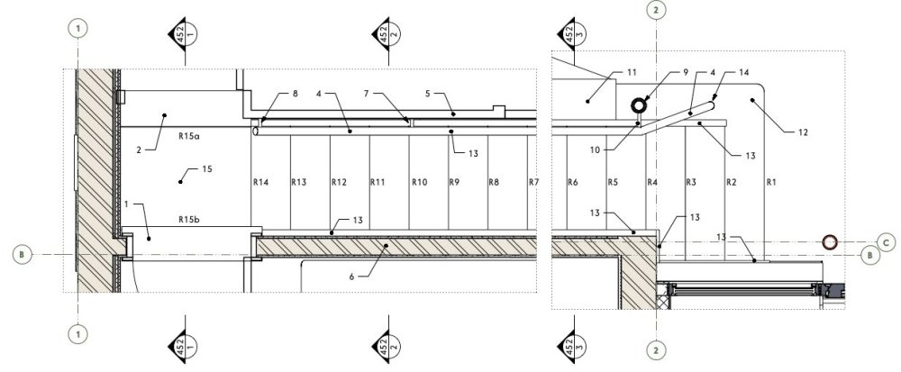
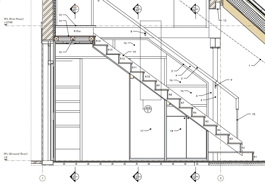
There are many occasions where it would be very useful to have a fully co-ordinated section line instance show up on another section viewport. For example here is a plan view of a staircase Marked on there are three sections (numbered 452/1, 452/2 and 452/3). These are fully co-ordinated with the section viewports they are associated with - if I want to move the location of a section cut, then the section line instance on this viewport will move accordingly. But I want to show these three cross-sections on the long section through the stairs too: In this viewport, those section lines have to be placed manually. They are co-ordinated with the relevant section viewports only to the extent that the viewport/sheet numbers will update with any changes - if I change the location of any of these sections I have to remember to come back to this viewport and move the section lines manually.