


line-weight
-
Posts
3,743 -
Joined
-
Last visited
Content Type
Profiles
Forums
Events
Articles
Marionette
Store
Posts posted by line-weight
-
-
9 hours ago, mjm said:
@grant_PD—super cool. Would you mind to go into a bit more detail on your SubD methodology for creating these objects. Much appreciated!
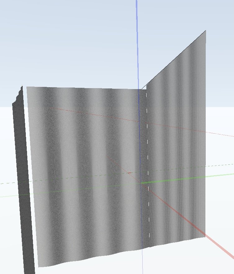
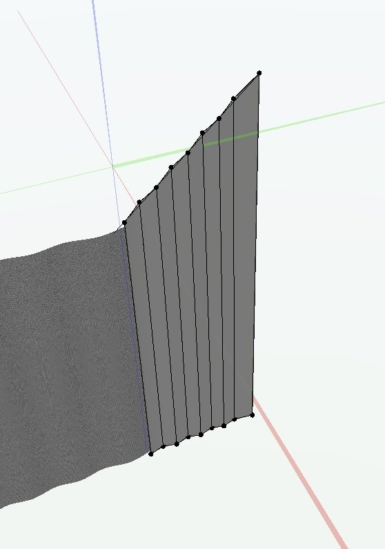
If that question is for me - as far as I remember:
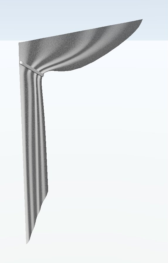
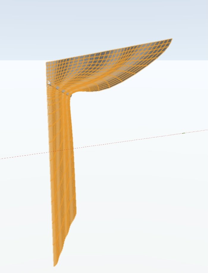
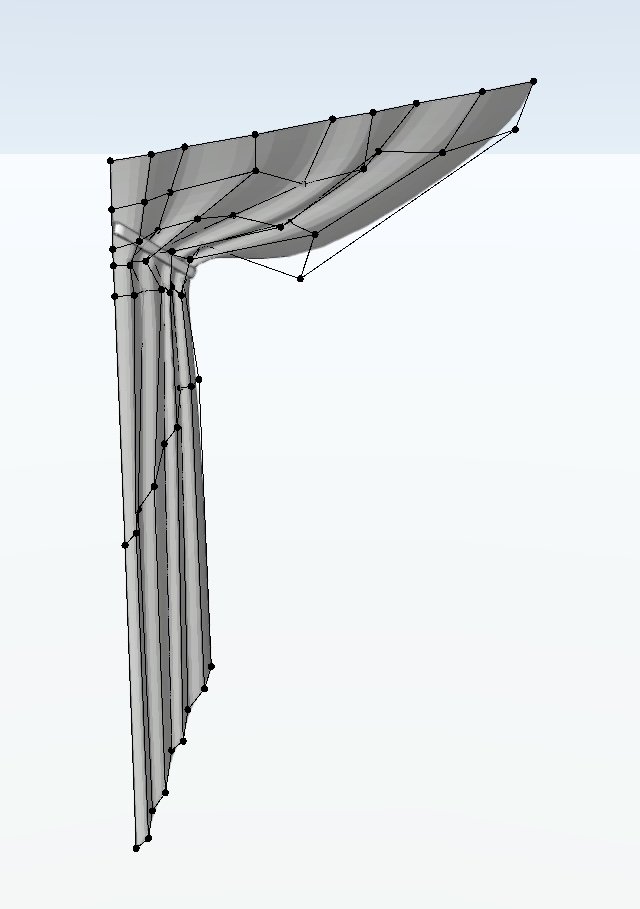
I started with a "square" subdivision primitive of the overall size of the curtain. Then divided it vertically several times. Then you can group-select nodes/edges to move them out of plane to create a basic corrugated surface. From then on, some manual tweaking to make them look a bit less regular. The ones that are gathered, obviously require a larger number of nodes, and then a lot of trial & error manual adjustment.
The fact that you can use the "3d dragger" thing on subdivisions means it's a bit easier to keep a handle on what you are moving and how, than with some other tools.
-
 1
1
-
 1
1
-
-
27 minutes ago, Pat Stanford said:
Section Viewports and the Section Style class were created long before there were "Styles" and styled objects in VW.
It is always a balancing act between making learning easier and not changing things that are known and understood by the existing user base. 🤷♂️
Sure it's a balancing act but I don't think the balance is right in this software. I believe there are multiple things like this, throughout the VW user interface, that could be changed in a managed way, if there were some kind of co-ordinated overview of usability issues including terminology consistency.
There are other applications I use where this kind of thing is dealt with via alerts of some kind, that let the user know something's been moved or renamed.
-
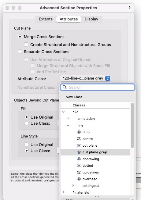
If you want a basic section with everything that's sectioned hatched, use:
- Merge Cross Sections
- Then where it says "Attribute class" there is a dropdown where yo can choose a class. In my example above you can see I've chosen "cut plane grey". That's a class I've set up with a thick lineweight and a grey fill. You can see I could also choose "cut plane" which is one I've set up just to have a white fill. You can make your own class with the lineweight and fill type you want. So in your case you can make one with your chosen hatch as a fill.
- Alternatively, as @markdd says, by default it'll use a pre-made class called "Section Style" which you can find in the class organisation dialogue, and edit to have the kind of fill attribute that you want.
If you want a section where the individual components are picked out, then choose "Separate cross sections" and *don't* tick "use attributes of original objects". Then it's the same again - choose your desired class in the Attribute Class dropdown, or edit the default "Section Style" class.
Vectorworks names this default class "Section Style" just to try and confuse us, because "style" has a specific meaning within VW but this is not a style - it's a class. They could name it in a way that helped users understand what was going on, but that's not how they roll.
-
2
-
-
15 minutes ago, Matt Panzer said:
The basic idea (when both are selected) is that the component will wrap to the Wrap To location if it finds it before hitting the insert's closure object (i.e.: jamb), then it will try to continue to wrap to the insert if it can.
Ah, OK.
I think this answers my subsequent post, which I typed while you were writing this.
*edit - or does it? I'll have to come back to this later...
-
1
-
-
23 minutes ago, Tom W. said:
I have been working on the assumption that a check in the 'Wrap to Insert' column overrode whatever the 'Wrap To' column was set to but judging on your settings above that was obviously wrong...
Yes this has confused me a bit too ... I'd expect that ticking "wrap to insert" would make the "wrap to" field grey out because it would no longer be relevant.
But it seems as if ticking "wrap to insert" for the plaster layer has no effect.
This is clearer to see when I make the brick layer thicker, because now the inner face of the window and the centre of the brick core are not at the same point.
Here I am asking for the plaster to be wrapped to insert like this:
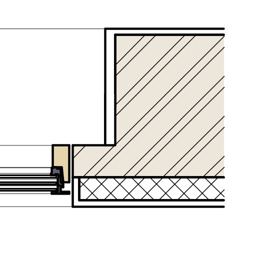
but it's being wrapped to the brick core instead, like this:
(vwx file attached)
-
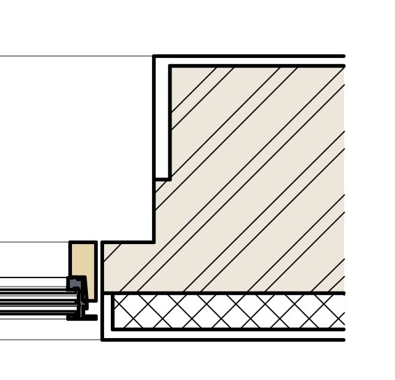
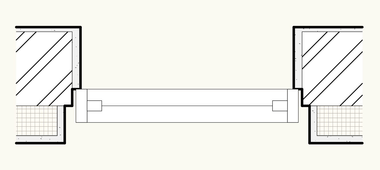
Ok - how about this scenario (I've added another wall component to the attached file).
Here, wrapping the interior plaster layer to the external insulation layer isn't used to force the entirety of the brick layer to be set back, so I get a step in it.
But what if I want it to look like this - is it possible?
-
I have had moderate success modelling curtains using Subdivisions. This makes them a bit easier to edit/adjust than is the case with lofts. It also makes that editing a little more intuitive especially if you want to do something like I have here, with a gather.
-
4
-
-
You've already worked out that you need to have "unified view" active?
Check that the other layers are actually set to be visible in the "organisation" dialogue.
If they are set to be invisible here then they'll be invisible even if you have chosen "show others" in the view options.
-
4 hours ago, Matt Panzer said:
Can you show an illustration of how you want that example to look?
Also, can you send me a file with that window in wall?
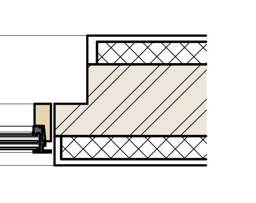
To be clear - for this particular wall/window combination I am able to get it to look pretty much as I actually want it.
This is just me exploring the options to understand what is and isn't possible. But say, for the sake of argument, I wanted it to look like this:
(I know that's not a very realistic example of something that someone would actually want)
I've attached a copy of the file.
-
29 minutes ago, Elite Exhibits said:
@line-weight maybe you know this - we have found the above to be another aggravation of Unified View
Peter
No I didn't know this.
-
- Popular Post
Of course in the longer term it would be best if hidden line could become more intelligent about how it draws things, so we don't have to resort to manual means, but in the meantime this certainly isn't a legacy feature.
-
5
-
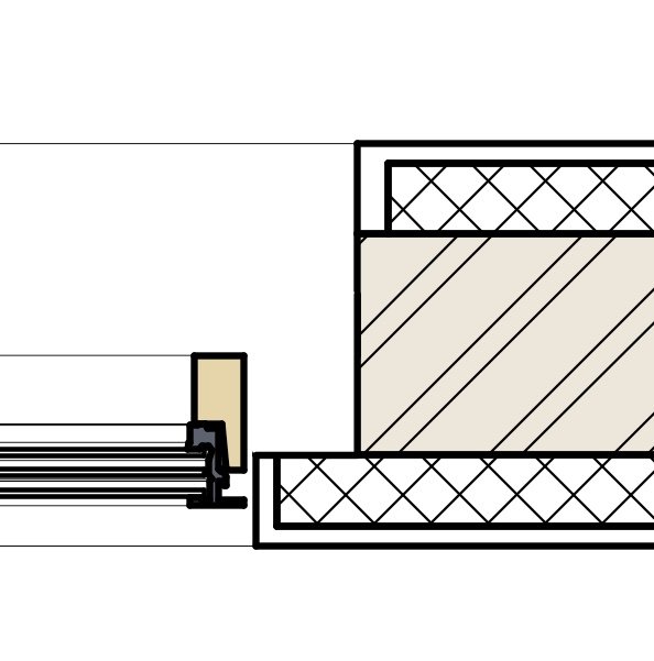
Here's an example - here's a threshold drain where I've modelled the slots in the grille (because then I can use it in a close-up section detail)
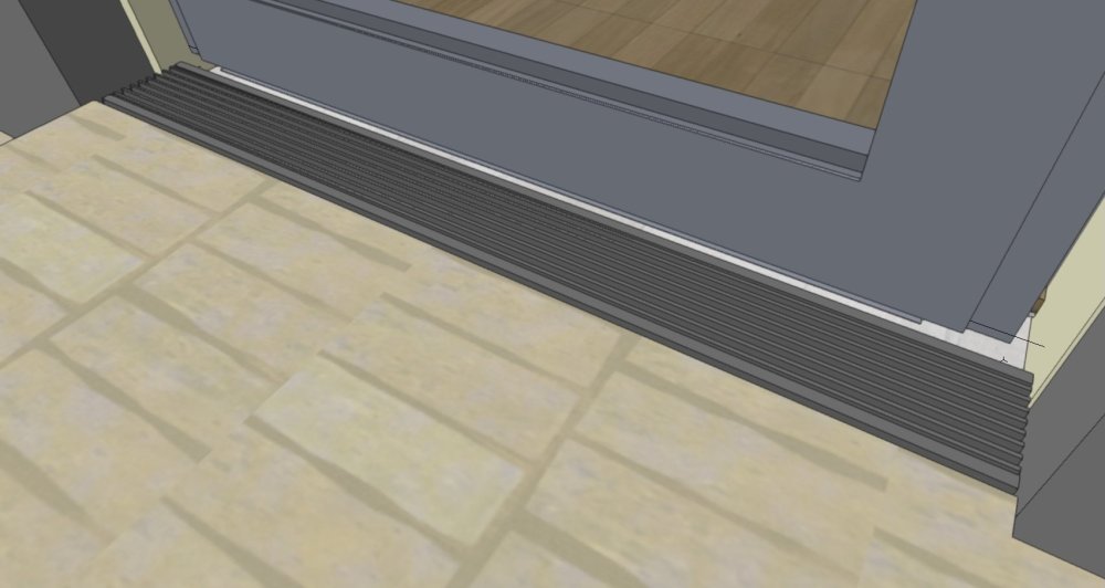
But when I come to create my GA floorplan, for which I use a horizontal section viewport, that grille is a mess drawn in hidden line - because VW draws all those lines next to each other and I get something that looks like a solid black rectangle:
I haven't fixed this yet. Actually this already caused a problem when the structural engineer thought that represented a solid wall.
Anyway, the way to fix it will be to symbolise it and then give it a custom 2d component in top view that will just be a simple rectangle. I can't generate that automatically because I'll have the same issue of the closely spaced lines.
-
1
-
-
12 minutes ago, Mark Aceto said:
All I’m saying, snark aside, is bury it in the Legacy 2D settings. As an entertainment user, I enable screen plane in my template file. A simple checkbox would solve this for all users in all industries. At the same time, add some standard behavior to control position and settings. Maybe this is something that was not possible before but with the new SaaS model, can be achieved in a future update.
Well, maybe let it be enabled/disabled. But it's not a legacy feature - it's a feature that's required for current workflows to work.
-
4
-
-
51 minutes ago, Matt Panzer said:
Ah yes - I see.
I can get my version to do the same:
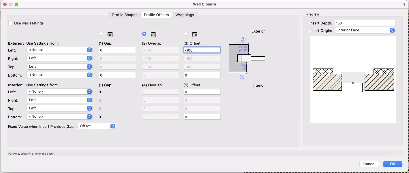
Giving a -100mm offset in the "profile offsets" tab for "exterior":
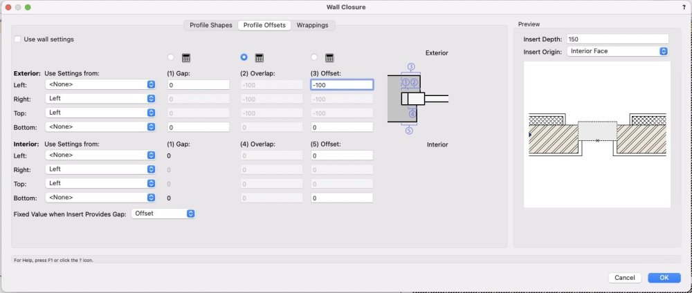
And it makes that offset happen along the boundary between the wall components.
But if I put a -100 offset in the "interior" part something different happens, it applies the offset in line with the inside of the window insert:

Which is why I think I'd decided this couldn't help me.
I'm not clear how it decides where the offset step-back is giong to happen... do different rules apply depending whether it's inside or outside of the wall core?
-
1 minute ago, Mark Aceto said:
The 2D geometry is ostensibly a hidden line render, so if I want to see a hidden line render of a 3D view, I’ll just render that VP in hidden line. I don’t have a use case where I will mix a few hidden line rendered objects in a wireframe elevation view.The same thing happens with Schematic Views when using Braceworks / truss workflows or any vertical structural member that can’t be tipped up from a laying flat position (truss tower, goalpost, torm). The end result is just another hidden line elevation view, so there’s really no point in creating extra work my myself.
That said, if I’m missing the utility of this feature beyond bathroom fixtures LOD, someone please post a screenshot of how you use it.
Do you work in a lighting/entertainment rather than architectural context?
I'm not familiar with braceworks and I don't know what a "Schematic View" is.
But for many of us working on architectural drawings, hidden line sections are rather crucial.
I don't actually use those 2d components as much as I could - but intend to start using them a bit more. And if you want to customise them at all, then flipping between these different components (and being able to see the 3d component geometry in the background) is rather useful.
-
1
-
-
38 minutes ago, Mark Aceto said:
Every other (3D) view is just a hidden line view that will render in hidden line anyway.
I don't understand what you mean here.
-
I find it a little annoying that it floats around and would probably prefer it to be somehow "docked" but I find it useful while working on symbols.
Recently I have been using it quite a bit flipping between 3d component/wall hole component/wall closure component.
That process could be smoother (often the view position seems to jump when moving between these components) but that's a separate issue.
One thing I like about this dialogue is that unlike so many VW dialogues it gives you a clear graphical indication of what's going on.
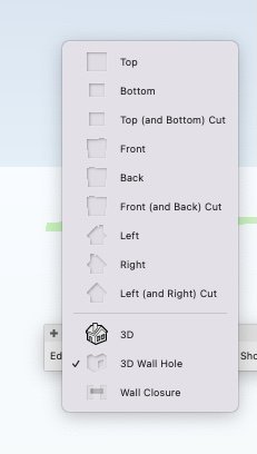
As well as making it easy to choose which one I want to edit, I can immediately see which component I'm currently working on, and which are empty or not. This is so much nicer than all the dialogues that convey information in hard-to-understand grids and tables.
-
3
-
-
Are we talking about the palette that only appears when you are editing a symbol?
-
1
-
-
For example... if for some reason I wanted the exterior detail to do this, it would be tricky, right?
Because the "profile offsets" bit of wall closure controls, it sets portions in or out based on whether they are adjacent to the window frame rather than per wall component.
-
Yes you're right that in the final detail, it might end up that I'd want an additional component anyway. But at this stage it's more proof of concept to understand what I can and can't do with these wall wrappings.
-
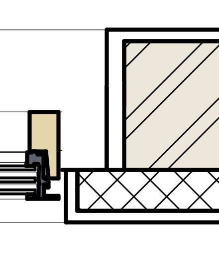
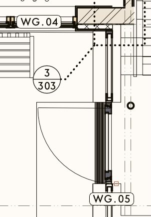
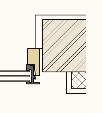
I'm now getting pretty close to what I want, using custom windows inserted as symbols into walls, and using the wall closure options.
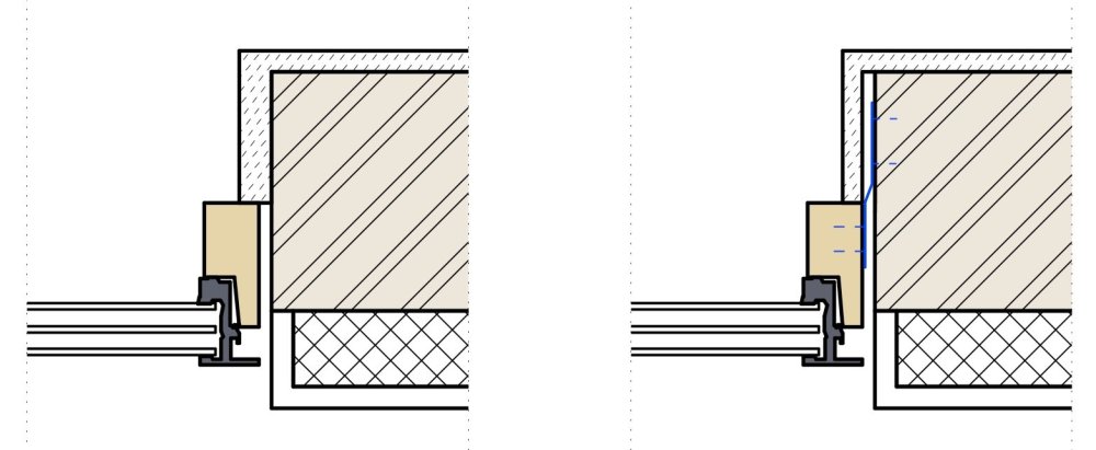
On the left is what I can get in a HSVP without needing to do any fixes in the annotations space. This is already pretty good - I can get the internal and external components to wrap pretty much as I want. The external render (at the bottom of the images) can wrap back to the brickwork, tucking in alongside the window frame leaving a gap of the width that I want. That gap I have made by making the hole cut component of the symbol slightly larger than the size of the windowframe itself (in place of what would be the "shim gap" using a window object).
And the internal plaster finish can wrap round and meet the frame, as determined by the wall closure component of the symbol (I could get it to slightly stand off the frame if I wanted.
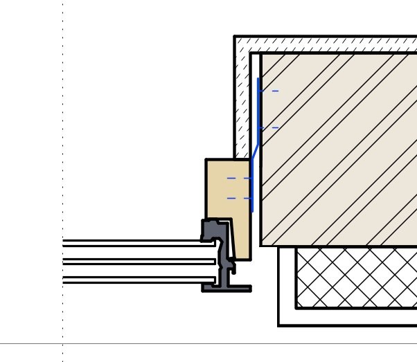
On the right, I've added some stuff in annotations, which I can't seem to do using the wall closure controls. Really I'd like the internal plaster finish to sail slightly beyond the edge of the brickwork opening, leaving a gap behind it where it wraps into the reveal because in reality there will be a metal fixing lug (indicated in blue) in here, which will need a bit of space.
Am I right in thinking I can't do that with the wrapping settings? The closest I can do is what I've shown on the left where I've just increased the thickness of that layer where it wraps into the reveal. I guess I could add another wall component, with zero thickness, in between the plaster finish and the brickwork, which could then wrap and gain a thickness in the reveal to create the void/stand-off but that seems a bit of a clunky workaround.
-
5 minutes ago, Pat Stanford said:
@line-weight I think about is slightly differently. I don't think about "Container Classes" but rather "Container Objects".
I guess what I have is "object classes" and these are intended to control visibility per object type.
In these classes might be a mixture of simple objects and "container objects".
Like so you have to be careful about unintentionally hiding things but if you are deliberate about it, I find it's a very useful way of making visible/invisible things that satisfy two criteria rather than just one. I name my classes such that it's always quite clear whether they are a "material class" or an "object class".
-
3
-
-
16 minutes ago, serge_01 said:
@line-weight interesting! my drawings are all in 2D, so it only draws 2D geometry. Would 3D geometry be faster than 2D, i cant imagine!?
My guess is that 2D ought to be much faster than 3D because it doesn't really have to calculate very much to show it to you.
-


Graphic legend - version for non-data objects
in Wishlist - Feature and Content Requests
Posted · Edited by line-weight
*edit* I see this is actually what @Amanda McDermott is asking for.
.
When I first looked at graphic legends, I came up against the same limitation that others are describing above - if you use the "object" type and you want the legend to display images of the relevant objects, there are only certain types of objects that this works for.
For me, it meant it was no good for what I was trying to do at the time.
I think graphic legends would be more useful if they didn't have this limitation.