
martinfdc
-
Posts
228 -
Joined
-
Last visited
Content Type
Profiles
Forums
Events
Articles
Marionette
Store
Everything posted by martinfdc
-
Subdivision Surface as Site Modifier
martinfdc replied to martinfdc's question in Wishlist - Feature and Content Requests
Thanks for the suggestion @Kevin Allen, in the end what I did was I created a Subdivision Primitive as a square then gave it the shape I wanted, then increase number of iterations and then converted the subdivision to 3d polygons, then I placed all of those polygons in the DTM-Modifier class. It worked perfectly! I attach a screenshot of the result of using the 3d polygons obtained from the subdivision objet.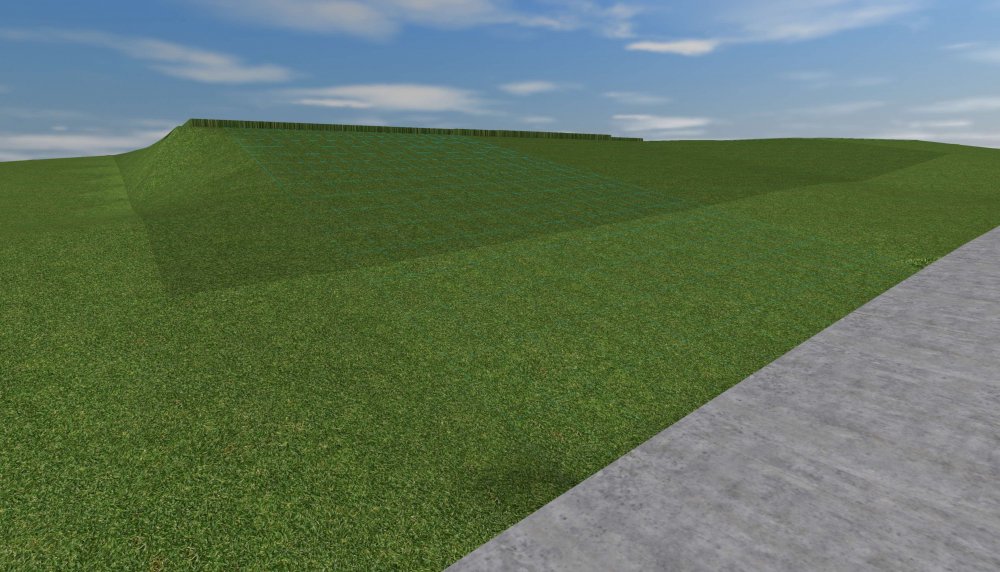
- 2 replies
-
- 1
-

-
- dtm-modifier
- site model
- (and 3 more)
-
Subdivision Surface as Site Modifier
martinfdc posted a question in Wishlist - Feature and Content Requests
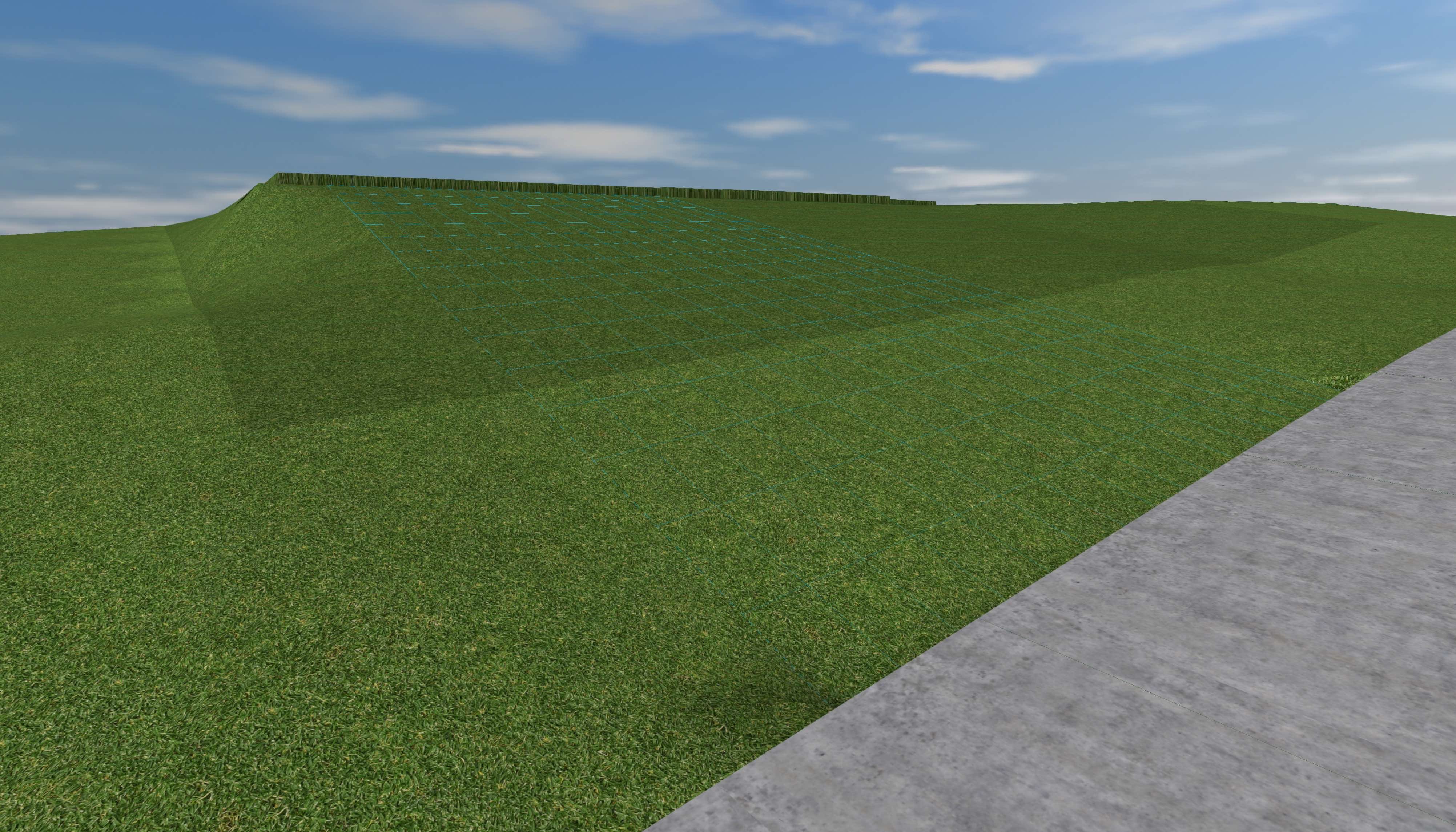
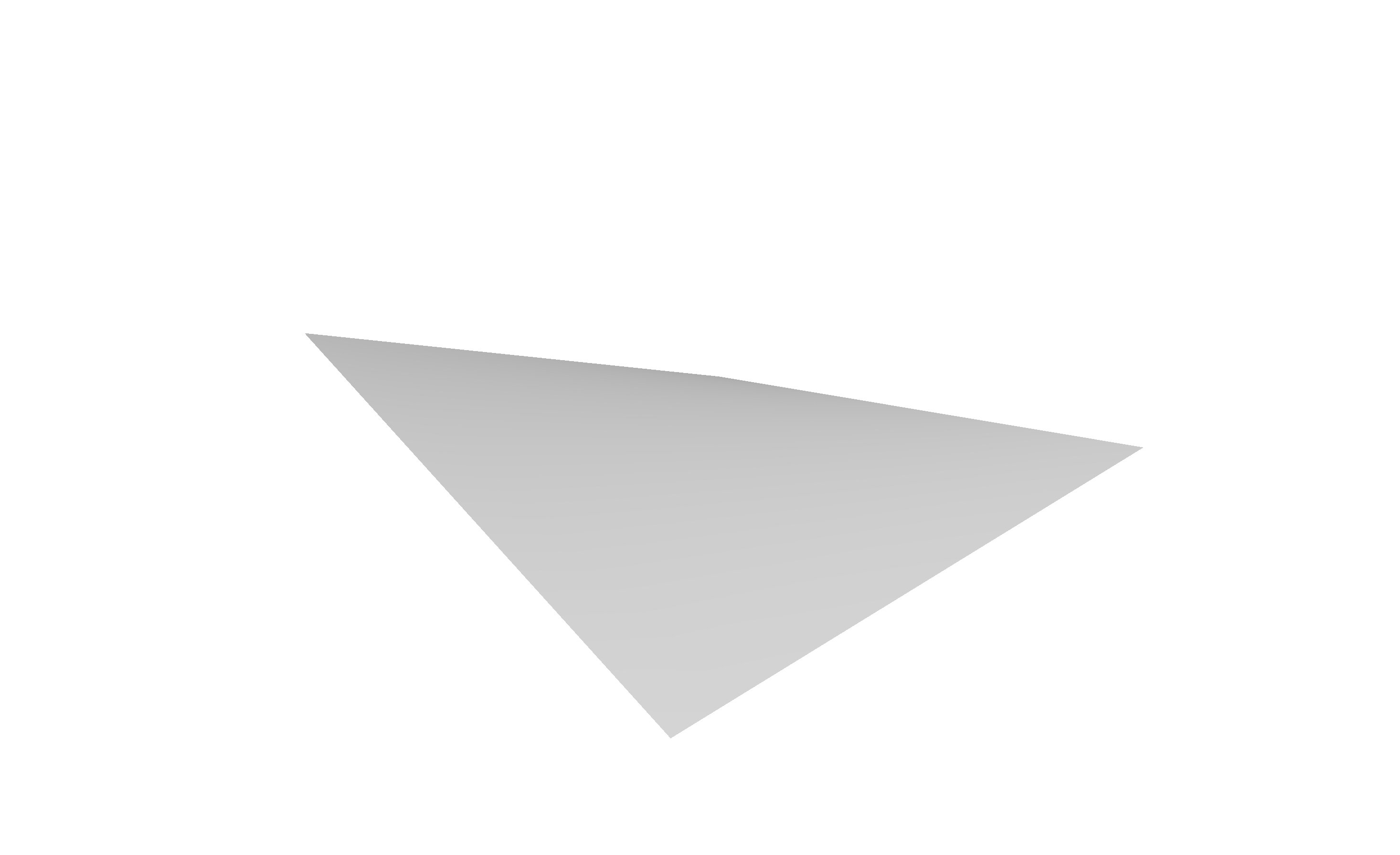
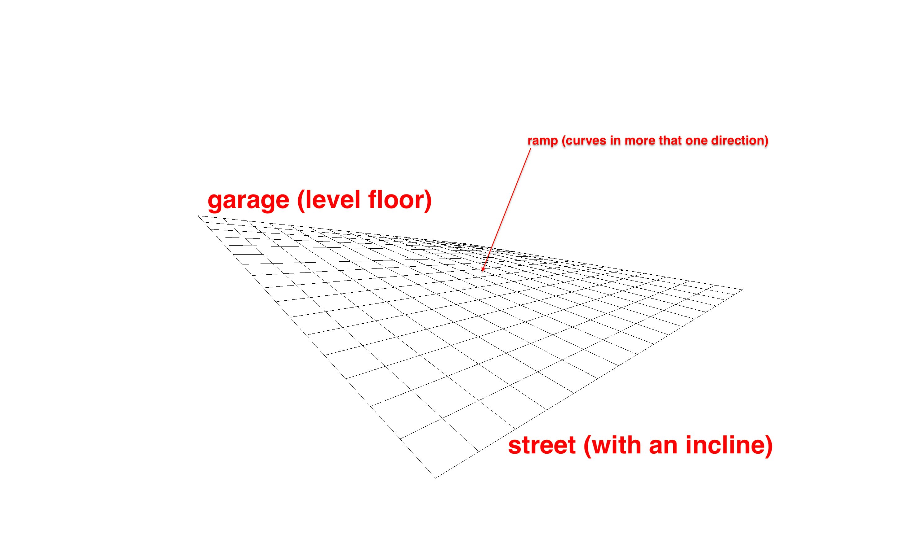
It it currently not possible to have a site model modifier that does a form like the images I attach. I have tried doing this with a 3D Polygon placed under the DTM-Modifier class but the site model reads 3D polygons as contour lines. The pad with slope doesn't provide the form I want to create either. I have also tried creating a 3D Polygon, converting it to Nurbs then via the 3D power pack>Create Surfaces from Curves, then Create Interpolated Surfaces, and then placing that in the DTM-Modifier class but then the site model converts that into a mesh with little information that does not contain the form that I want. So the best way to create this strange shaped would be with the subdivision surface. I hope one day one can use this object as a site modifier. Or it could also be created via an interpolated surface but then the site model should respect all vertices and not read the interpolated surface as quite a basic mesh when the interpolated surface is in the DTM-Modifier class. Maybe I'm totally wrong and doing this type of form in a terrain is possible, if so, I would be very glad if someone tells me how can this be done. This type of form occurs many times in the real world, for example you have a ramp that's connected to a street with an incline and to a garage that it's entry level is straight...

- 2 replies
-
- 1
-
-
- dtm-modifier
- site model
- (and 3 more)
-
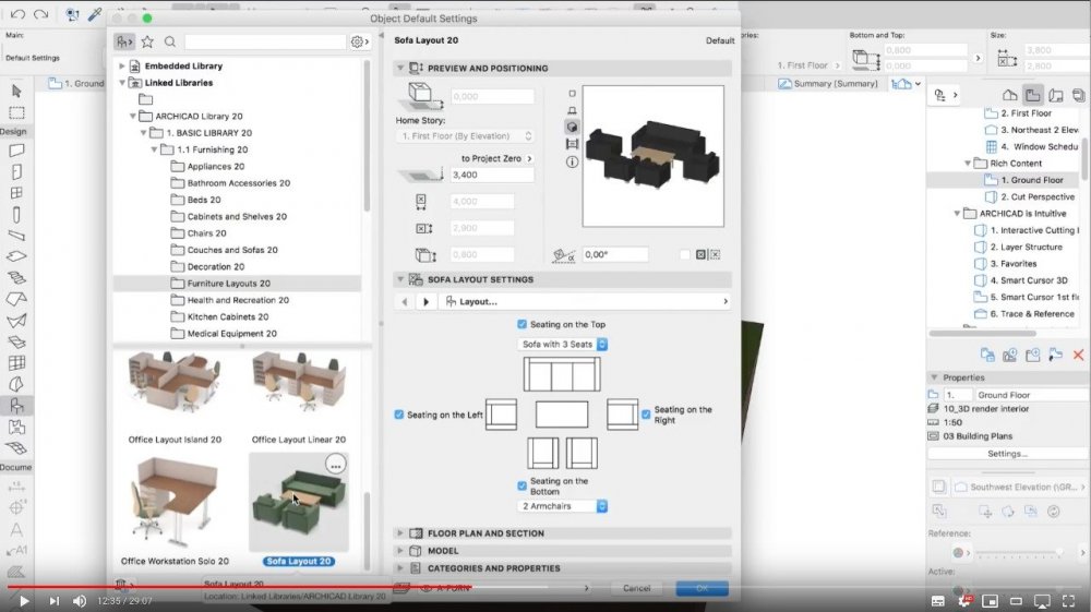
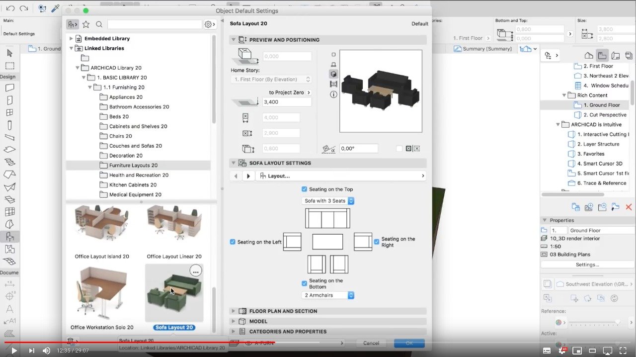
Would be handy if VW could have a similar tool to the one archicad has that helps create a quick sofa layout... Very handy for placing furniture on living rooms or waiting areas... Take a look at the screenshot I provide and also have a look at the youtube video I post from minute 12:35 onwards. Hope someday it becomes a feature! video (fast forward to minute 12:35):
-
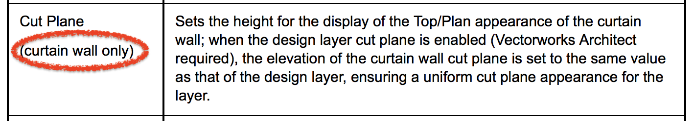
According to the Help site... (http://app-help.vectorworks.net/2018/eng/index.htm#t=VW2018_Guide%2FWalls_edit%2FEditing_Walls.htm&rhhlterm=wall layer cut plane&rhsyns= &ux=search) The Cut Plane feature only works with curtain walls.... It would be extremely useful if it could also work with standard walls. This would solve the problem of how to draw the example I mentioned above...

-
@nrkuhl couldn't agree more with you in this wishlist item! I hope we soon get a feature that let's us represent properly cases in which a wall is above the cut plane... like in this case:
-
@Boh no it doesn’t... at leat it hasn’t helped me in any way...
-
Does anybody know if representing this wall and window situation can be done correctly in VW 2018 or 2019? I have this sort of problem all the time in VW.
-
Pillar - left and right texture option
martinfdc posted a question in Wishlist - Feature and Content Requests
Hi, Would be great if the Pillar tool could accept left and right textures. I think the Pillar tool is a superior tool when compared to the wall projection tool. The projection tool always causes issues when the projection reaches the ends of walls. The Pillar tool works great always. You can join walls from everywhere and it works. Maybe even rename the Pillar tool to Irregular Wall or something like that because thats the way it works best. -
Custom Sash Horizontal Slider Window or Door
martinfdc replied to martinfdc's question in Wishlist - Feature and Content Requests
Hope this wish list item makes it to Vectorworks 2020! Or even better if it makes it to Vectorworks 2019 in a service pack! -
I hope one can send forward windows in Vectorworks 2019 in order to have the line weight of the wall cap show.
-
Wesley, I have noticed that if you leave your Vectorworks model in axonometric view and in Open GL it works better. Because if I have it in Top/Plan after two export it simply doesn't export anything. But if I leave it in axonometric view and Open GL then I get the exports I want but they still have broken instances and some instances are deleted but the null containing the symbol still exists...
-
Hi, I'm using the Send to Cinema 4d command and the fist time I did the export everything worked perfectly. Now I have updated my project in Vectorworks and have wanted to Send to Cinema 4D once again. The result is terrible. The main problem is that many Instances of Vectorworks symbols are now broken and some symbols export with no texture tags. It's not possible to work this way. One needs to be able to update the Vectorworks model and send it to Cinema 4D.
-
reinstalled VW and I can use foliage once again with no issues...
-
Hi, I'm wondering if there is a way to save a render in pixel dimensions instead of what's supported in sheet layers which are millimeters. I'd like to export a render the way you do in Cinema 4D, by telling the width and height of your rendered image in pixels... This would work if one would want to make a render that would fit snuggly to a specific 4K TV or any screen really... Hope someone can help me figuring this out. Thanks in advance.
-
Same issue is happening to me....
-
A bit late but better late than never! Many thanks to all for your replies. They have helped me a lot.
-
Hi, I would like to know what can one do in order to make renderings with Displacement Mapping finalize faster. After I turn on displacement mapping in my renders, the calculation of indirect lighting takes forever... Thanks in advance!
-
Would be great if one could also see the wall start mark when looking at a wall in axonometric or perspective views, not only in TOP/PLAN view. Look at the images attached, you can only see the wall start mark in the TOP/PLAN view... Hope this gets implemented soon!
16_32_21.thumb.png.e484355f4ec3fa4c0a8f6d0f85da1ebe.png)
16_32_34.thumb.png.3cd799208b5781ce6c4821fe4ab73df9.png)
16_32_41.thumb.png.19d40de0644986e5e471613e2e0151d2.png)
-
Move by Points Tool
martinfdc replied to zoomer's question in Wishlist - Feature and Content Requests
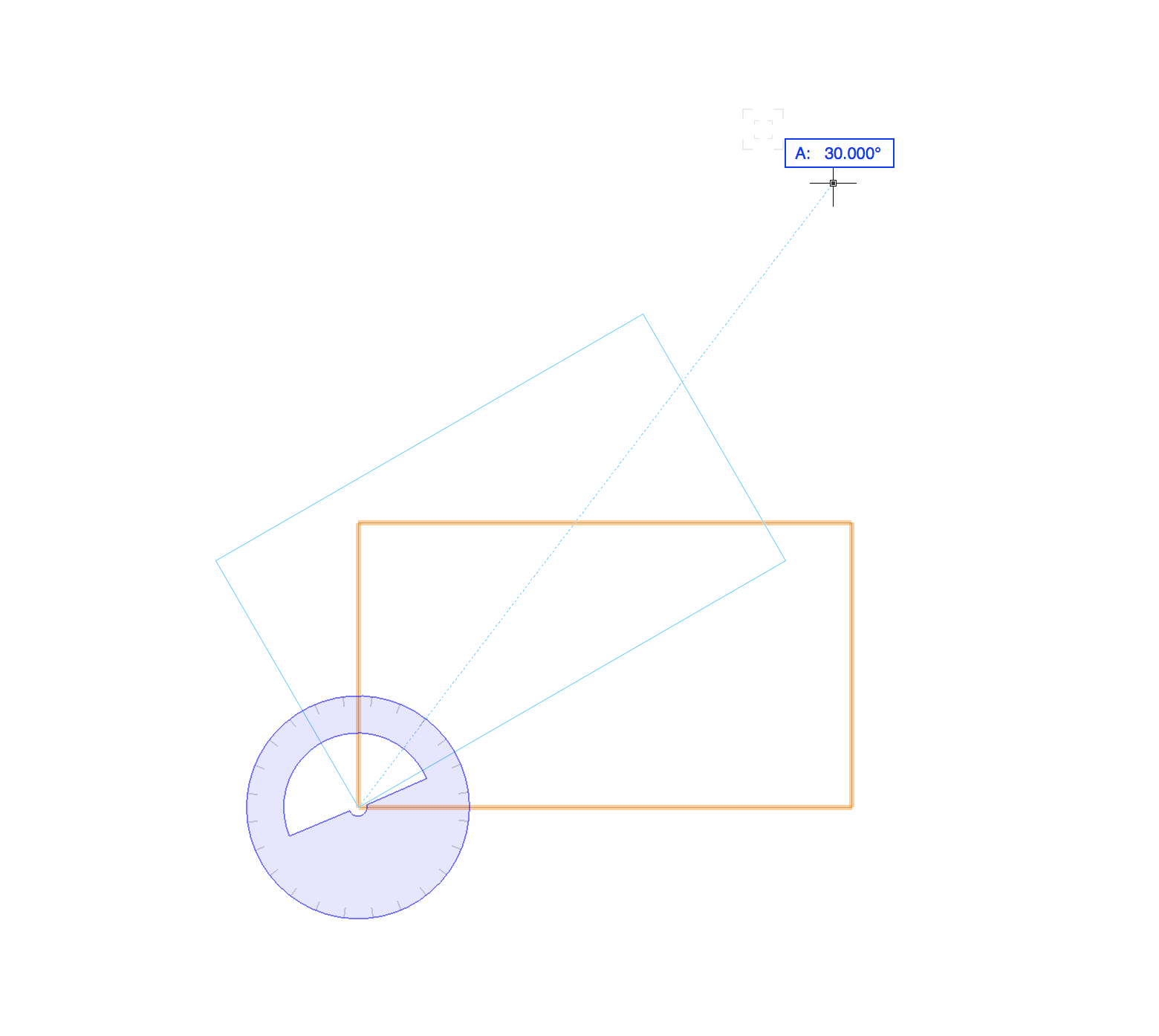
Hi, Would be great to have a preview of the MOVE BY POINTS tool before one actually finished the order, similar to the preview one gets with the rotate tool. I leave an example of the preview one gets with the rotate tool: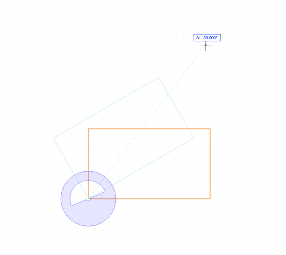
-
Automatic Camera Vertical Tilt Correction
martinfdc posted a question in Wishlist - Feature and Content Requests
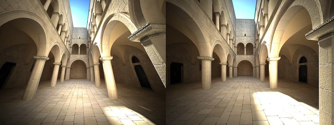
Hi, It would be very useful that the Vectorworks camera would have a feature that allows one to make sure that all vertical lines are vertical. Similar to what a perspective correction lens does in a real camera. With this new tool we could make sure that all of our renders come out with completely vertical lines and a great perspective instead of one that is deformed. It would also make things faster as one would need to fiddle less with the camera in order to get vertical lines. I attach a photo that makes clear what I'm talking about. I took the images from V-Ray for Cinema 4D Manual: http://vrayc4d.com/live/vrayforc4d-manual/vray-physical-camera/vray-physical-camera-examples/ V-Ray has automatic vertical tilt correction. Hope this gets implemented!
- 5 replies
-
- 7
-
-
- camera
- renderworks
- (and 3 more)
-
Walkthrough Gamer Mode and Multiple View Panes
martinfdc replied to martinfdc's question in Troubleshooting
just so that you experience the problem quickly, please move your mouse a lot and long distances (by long distance I mean, displace your mouse in your table for a long distance) and in circles, large circles... -
Displacement mapping relative to applied object size
martinfdc replied to martinfdc's question in Known Issues
Still no fix of this issue in VW2018 SP2! I hope the fix comes in SP3... -
Hi, the walk through gamer mode does not properly work when using the new Multiple View Panes. It seems that when one is "walking" and guiding oneself with the mouse, as soon as the mouse goes over another of the view panes an error occurs. It's difficult to explain. But it's very easy to experience. Just open a document which you can gamer walkthrough, then click Multiple View Panes and in one of your view panes activate the Walkthrough Gamer Mode, you'll immediately see the problem that occurs. Hope this gets fixed soon!
-
Displacement mapping relative to applied object size
martinfdc replied to martinfdc's question in Known Issues
Great. I'll be waiting for news! -
Displacement mapping relative to applied object size
martinfdc replied to martinfdc's question in Known Issues
Here you have @JimW Displacement_Mapping_Problem.vwx
16_32_21.png.be2b02c28805f2bd0ee5d2f04f79cb92.png)
16_32_34.png.bf039a10d67458f0877a0c532a9b53db.png)
16_32_41.png.7a3a440367c29bcea6e8c9ca27059618.png)