MHBrown
-
Posts
333 -
Joined
-
Last visited
Content Type
Profiles
Forums
Events
Articles
Marionette
Store
Everything posted by MHBrown
-
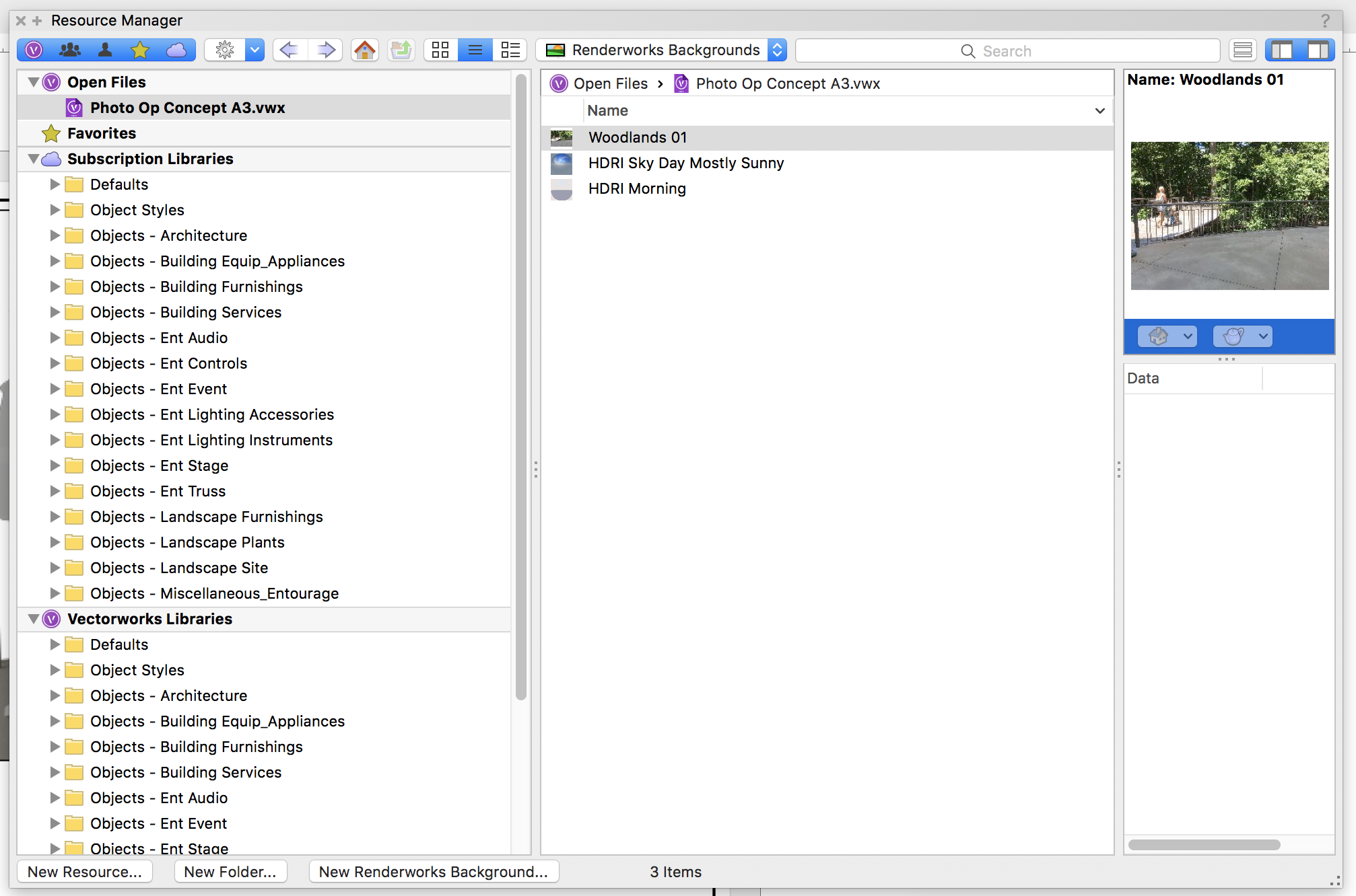
I created a Renderworks Background and I can now see it in the Resource Manager. I'd like to edit it, however there does not seem to be an "edit" option anywhere in this expansive window. Am I just missing it? VW 2018 SP2. I'm including a screen shot. It includes everything except "edit." I've gone through all the pull down menus I can find. I know it must be there somewhere, but where? Thanks, MHBrown

-
As of July 13, 2018, Combine Surface cannot be used with all closed polylines. This used to work; now it does not. All polylines are closed with no intersecting geometry. VW2018 on Mac VW2018 SP2, build 401138. Mike
-
To, Gadzooks, Thank you, but that doesn't work either. I think something was changed in VW, the MacOS, or with the Xerox driver software that has broken the ability to tile VW drawings. This is an unfortunate event for me, limiting the size of my drawings to 11x17. I appreciate your advice, however. MHBrown
-
Up to VW2016 I was able to print oversized drawings by tiling the output. I could print at 200 percent over four sheets of 11x17 paper. In VW2018 I cannot seem to do this. Even when I set it up the same way in the Page Set up it only prints to one 11x17 page (though it prints the four quadrants of that sheet in the manner of a tiled sheet: four separate mini-versions of what I'd like filling four separate 11x17 sheets.) Can someone explain what is up with this? I seem to remember a "tile drawing" option or something like that. Has that been removed? MH Brown
-
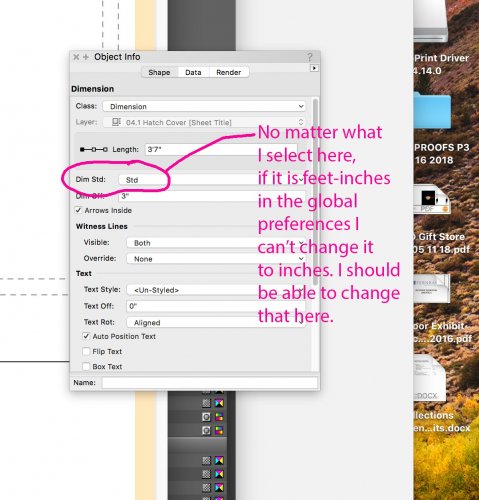
Thanks, Art. I'll try to create a style and see if I can get that to work. It would be nice as a Viewport preference, too, just as scale is. To Kevin, I flip a coin and then set my units to either "feet and inches" or "inches." It doesn't matter because ultimately I'll have to change it in my Document Preferences and print one page at a time. Perhaps I wasn't clear in my OP, but I'm not only talking about dimensions under one foot. I'm talking about creating drawings that the builder will be most comfortable using. Most woodworkers prefer inches, for example, so my dimensions would read 43" and not 3'-7". All the other dimensions would follow suit. Someone running a milling machine would prefer 43.00" because that would inform him of the tolerances involved. A house framer may prefer the 3'-7", but drawings should always consider the person using the tape measure on-site. At present, Vectorworks is missing this very fundamental feature. It's probably not sexy enough to promote as a "new feature," so it is not addressed at all. In my mind, however, proper dimensioning should have been near the top of the original MiniCAD features list and have stayed there. Thanks to all for the replies! MH
-
Am I the only person who needs to use different units in a single drawing set? With all the changes and additions to VW over the last few decades, why is something that seems so basic still apparently missing? Please, someone tell me I'm totally wrong and it has been added. Here is my problem. When I'm dimensioning a site plan, feet and inches works great. But if I'm dimensioning a drawer in the same drawing set, am I expected to use something absurd like 0'-6 1/4"? I'd like to simply have my dimension read 6 1/4". So do I have to have a completely different file based on the units I'm using? Talk about the tail wagging the dog. Please don't tell me to use dual dimensions and just "turn one off." That is not an answer. The correct answer is to be able to select units in the Object Info Palette. When will this be implemented? Is it there now and I'm just missing it? It would be great if someone could point me in the right direction. Thanks, MH
-
I used to be able to export a set of VW saved sheets as a PDF. This straightforward, elegant system has been replaced in VW2018 by what I find to be an awkward and broken "Publish" command. When I invoke this, it neither gives me a chance to name the file nor choose where it goes. It acts like it is printing the file, but it doesn't print (by the way, if I wanted to print I'd choose print!!) When I press "Select Folder," it does not send the file to that folder. I have no idea where it goes, if it goes, or what name to search for (if you recall, there is not opportunity to name the file.) The "File Export Options" does nothing when selected. There is a menu with poorly named choices, but nothing happens regardless to what is selected. I get an annoying message that the Publishing was successful, but it is not. It then automatically opens my Vectorworks 2018 folder. This is a seriously rotten system and it needs to be fixed. It should work like this: 1. Publish (or export) to PDF 2. Choose files 3. Save as a set? yes/no 4. Name set 5. Choose Destination Folder 5. Options: PDF quality 6. Start. It is pretty simple. Please fix it. MHBrown
-
Thanks, but that hasn't worked for me since VW2013. I have to delete and insert the new one. Perhaps it has something to do with my title block being a symbol, but I assume most users make their title block a symbol.
-
Has anyone else noticed that the Data Stamp still doesn't work in the newest version, VW2017? Specifically, the file name does not update automatically nor will it update by "refreshing" in the info palette. The date updates using the info palette, but the file name will not change. The same workaround as we previous versions is required: delete the existing stamp and replace it with a new one every time you update your file. Is this just happening to me or is it still a bug for the bug list? MHBrown
-
The best thing was the way it has been since at least MiniCAD 5 (ca. 1995) and that is to have unfilled things render as wireframe and the wireframe renders in the color selected. It's pretty straightforward and very useful since transparencies are not supported in all rendering styles. Even with a house, it might be nice to leave the window glass as unfilled so that they can be rendered as "transparent" in hidden line. A complicated programming fix would be for VW2018 to include a "Render transparent objects as wireframe" option for the rendering styles that do not support transparency. Or just fix what has been, in my opinion, broken in the move to VW2017.
-
Thanks to everyone! The only problem with giving my acrylic a fill is that I think they will render as solid when I do a hidden line rendering. I'll try the NURBS "trick" and see if that works. I'll do a little experimenting and see what works. Again, thanks for everyone's help. MHBrown
-
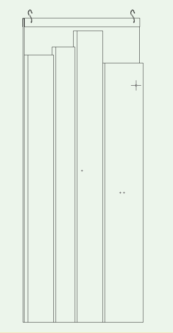
Thanks to all, but lost in this is the fact that since Renderworks was offered with VW, it has always rendered unfilled objects as wireframe. The "wire" having the color selected by the users pen choice. Is this no longer the case? It's always been an easy way to create a transparent effect in renderings (good enough for my purposes) without the rendering time "hit" taken when rendering transparency. They can't be completely transparent or my client will think all the objects on the cases are uncovered. I don't want to give them real geometry (i.e., each box made out of five 1/4" transparent panels) because of the rendering hit there. It has always been simpler to just leave them unfilled and give the lines a "glass" color. Light blue seems to get the idea across. By the way, Jim, don't extruded rectangles have "...actual 3D geometry"? Lastly, will they always render black now and not blue? Should I change them all to NURBS curves? If I do give them a fill, can I control the transparency without making a texture map that is 90 percent transparent? Hope that makes sense. Thanks to all for the help! MHBrown
-
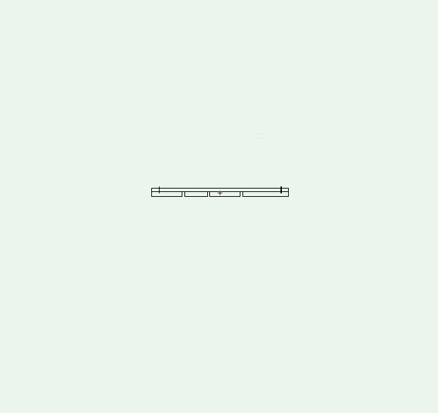
They are extruded rectangles with no fill, just an stroke color (light blue).
-
Just installed VW2017 and the High Quality Renderworks seems to have a bug. When rendered in VW2016 the solid black lines seen in this rendering (representing clear acrylic tops) render the color they are drawn at: light blue. As you can see in this image, VW2017 renders them black. I'm using the SP4 version of 2017. Any ideas? I tried changing to Custom Renderworks and tweaking a bit, but the results are the same. I'm on an iMac, with 16GB RAM running OS10.12.6 Thanks, MHBrown
-
Thanks for the help, Pat. It is the most simple of spreadsheets. The first column has about 100 numerals (some have initial letters, i.e. "R915"). The second column has the names of the objects that correspond to the numeral. For example: "456 Shoe" would have "456" in the first column and "Shoe" in the second column, but both in the same row. It's just like an Excel spread sheet. I want to put them all in numerical order, so it is a simple numerical sort by the first column. It does not get any simpler, nor more fundamental. My workaround is to do it in Excel and copy/past into the VW sheet. That works OK. I don't really think a script should have to be written for something this basic or is this VW worksheet for something other than what I thought it was for? MHBrown
-
Different ways to organize column data in a worksheet
MHBrown commented on PVA - Admin's article in Knowledgebase
This doesn't work in VW 2016 on a Mac. Even if it did, it's a very odd way to design a sort command. Why not just select what you want to sort, select "sort" from the edit menu, and select the column criteria for the sort. All this icon dragging is not intuitive. Oh, and did I mention that it doesn't work? The icons are always grayed out and do not drag anywhere. -
In VW2016 I created a simple worksheet of objects. Each object has a unique number that may be "123" or "R123" with the numerals "123" representing any of the 1,000 combinations of three digits. These numbers are in the first column. The second column simply has the name of the objects. I was given a list of objects that was not in order, thinking I'd just enter them as listed and I'd sort them once they were in the worksheet. I figured there would be, I don't know, a "Sort" command. Well, I think there is a sort icon, but it is grayed out. So my question is, why does this version of VectorWorks have light gray dummy icons that seem to do nothing? No matter what I do, it will not sort. Any ideas as to why? Thanks, MHBrown
-
One or more operations were aborted due to lack of memory
MHBrown replied to MHBrown's question in Troubleshooting
It happens with files of different sizes and there is no single tool or operation that triggers it. This time it happened after VW crashed. I opened the file back up and started getting the message. Let's assume that it is a correct message first. What does it mean? -
One or more operations were aborted due to lack of memory
MHBrown posted a question in Troubleshooting
I'm using Mac VW2016 sp3 and this ancient bug is popping up again. This problem has persisted since at least 2008. Has it never been fixed? Why am I getting this message? I have 16GB of RAM and VW is only addressing around 500GB according to Activity Monitor. It also says I'm using 8.44 GB of memory total, about half of what is installed. Clearly, this is a bug, but is there a work around to reset it so it stops popping up? Back in 2008 and 2009 there were some suggestions, but I assume those are not valid any more. What is up with this? Why has it not been fixed...or am I the only one seeing it? Thanks, MHBrown -
Thanks, Jim, but I get that dialog, so don't have it set to always give me the same thing. I regularly only need to change the 2D or 3D geometry. Thanks Andy and Kevin, those are helpful tips. Andy's adds an extra step and Kevin's makes me have to stop what I'm doing and hunt in my Resource palette, but both will work. I still think it should just behave as before, but these are good tips to have handy! MHBrown
-
It used to be that if you double-clicked on a hybrid symbol you would be taken to a window showing the symbol in way it is stored, i.e. the way it was created. This made it easy to edit since, more often than not, symbols placed in a drawing are at odd angles. In one of the "teen" versions of VW this was lost. The workaround was to double click the object and immediately go to Top/Plan (the 2D mode). In an odd animated way, you would watch the symbol swing itself around until it reached the aforementioned way it was stored. This was an extra step and required watching the little animation, but it got it in the correct plan view for editing. The problem is that if you go to any other view of this object it reverts to the view from the drawing. In other words crooked, aka, useless. What is the point of that? I realize that this is a programming mistake and that the "Top/Plan" patch was quicker than rewriting a bunch of code. It is, however, totally half-assed since it only allows proper editing in Top view, neglecting the other projections. I think VW needs to bite the bullet and fix this unless there is a way to edit symbols that I'm not aware of. Is there? As it stands now, I have to place a copy of the symbol in my drawing and edit that un-rotated version. That's pretty absurd since it used to work fine in VW12. How do others edit symbols other than double-clicking on them in the drawing? That has always seemed the most straight forward for me, but after 22 years of MC/VW I might have a number of legacy methods that are no longer correct. MHBrown
-
According to a little window that randomly appears on top of my VW drawing, I have the opportunity to upgrade to VW 2017. My decision rests on one question: Will the Data Stamp in the Tool Set palette update the file name, the date, and all other displayed information when I select it and press "Update" in its info window? At present, it changes the date, but it does not change the file name (when I've renamed the file, of course, with a "Save As"). It's been this way for quite a while. Thanks, MHBrown
-
To Alan, If I need to draw on an angled face, that is a "rare occasion" where I use the Working Plane mode to view something straight on. It seems only really useful in limited ways because there are so few commands that recognize you are in that orientation. If I use the keypad for front, left, right, etc. It just reverts to the screen plane...even if I've chosen "working plane only" or "Screen Plane or Working Plane." There may be a way to use it, but it doesn't make sense to me. I never use the push-pull tool. I'm not even sure what it is. Generally, if I want to make an angled side of something I draw its side view on an angle and then extrude it. MHBrown
-
Thanks, Kevin, that works. However, it means I can't edit symbols from my layout. I have to find an open space, go to the Resource Browser, find the symbol in the list, drag it into my drawing, make the changes, go back to the layout and see how it looks. In the previous versions, the symbol would go to the orientation in which it was designed right away--usually a useful (and carefully chosen) orientation that made navigating with the number pad easy. I can't imagine a situation where you would want to edit an object looking at skewed orthographic projections. Certainly that should NOT be the default. That is why, even if it is as designed to work that way I label it a "bug." A "bug" is not always an error in math; it can also be an error in judgement by the programmer (I imagine it was an error in the programming, but it was left as is). Thanks for the workaround, but I hope it is fixed someday. MHBrown
-
Here are two screen shots inside a symbol mode. Before, VW2016, you could double-click to edit a symbol and you would get the orientation in which the symbol was created. This is the only way it should work. Why would you want to work on a symbol that was angled? I was told this was fixed by invoking the Top/Plan view to return to the correct view. The one screen-shot shows this. When I go to front view, however, it is wrong. It uses the placed view instead, angled rather than flat. Has this bug been fixed for VW2017? Thanks, MHBrown