Boh
-
Posts
1,704 -
Joined
-
Last visited
Content Type
Profiles
Forums
Events
Articles
Marionette
Store
Everything posted by Boh
-
Site model - understanding "existing" and "proposed"
Boh replied to line-weight's topic in Site Design
How does this way loses cut/fill info? I would suggest having two DTM both created with the exactly the same (existing) source data. The extg site model would have no modifiers applied to it and would just be used for as-existing plans/elevations/sections. The other would be the proposed site model which would have site modifiers applied and thereby cut/fill calcs are possible. The option to show the "existing & proposed" contours in top/plan view is also available. As you say though the DTM snapshots does keep a history of changes as well as the opportunity to show the DTM in different styles. I guess they could also good for complex files to just import a snap shot of the DTM held in a seperate file as the DTM's can bulk up a file if complicated. -
Hmm apologies, I may have confused you in my previous post as I am getting my line naming slightly wrong. I've edited my previous post: So i've done a little research and there are a few types of "polys": "polygons" are flat polys with only corner vertices. They may not be on the layer plane or horizontal but they will be flat. If you change one of the vertices of a polygon with the reshape tool to any of the other vertice types (fillet/spline/bezier etc) then you will see in the OIP that it has changed from a "polygon" to a "polyline". A "polyline" can have any of the vertice types but is still flat. You can convert either polygons or polylines to "3d polygons". Polygons and polylines cannot be used for site model source data but 3d polygons can. 3d polygons do not need to be flat (i.e. their vertices can be moved to any z height) but like 2d polygons they can only have corner vertices. If you convert a rounded polyline to a 3d polygon the rounded portion will be broken down into a bunch of straight segments. 3d polygons viewed in top/plan view have no fill. Note that a polygon located in 3d space is not a "3d polygon". So coming back to your site model issue was the poly in your site model source data an actual "3d polygon" or just a polygon sitting in 3d space? If the former then it should modify your site model.
-
Importing a Vectorworks drawing as a referenced viewport
Boh replied to StatonCohen's topic in Site Design
Check the correct classes and layers are on. check if the viewport crop is in the correct place. Check the viewport is in the correct projection I.e. Top plan , orthoganal etc. If the viewport is 3D projection check the render style. you could also try the eye dropper tool to copy attributes from the correctly displaying viewports to the one you are having trouble with. Cheers -
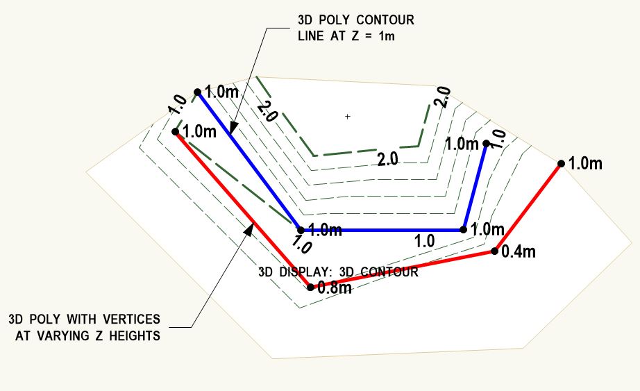
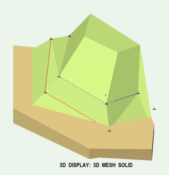
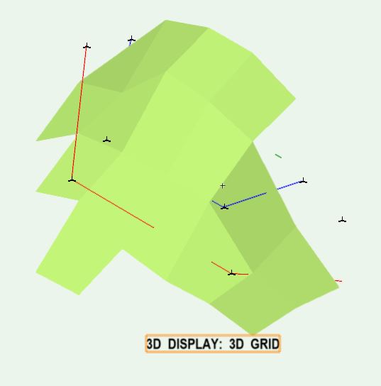
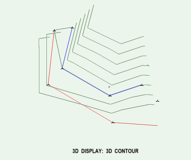
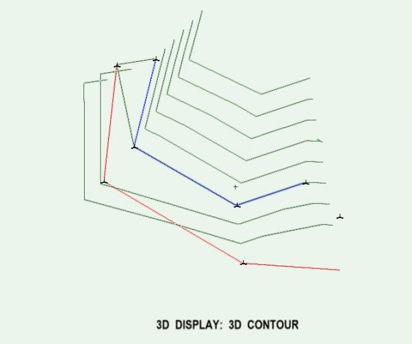
It's a 3d polygon. Yes I don't think polygons (even if in 3d space) are valid as site model source data. They need to be 3d polylines, 3d loci or stake objects. You can just use 3d locii however i prefer 3d polylines even if it is only their vertices defining the site contour as it helps group them into one object rather than having a whole bunch of 3d locii. 3d polylines with vertices at varying z heights are also typically imported into VW from surveys dwg files which are then often used to create DTM's. I've done a quick site model with 3d polylines in it as source data. I've also duplicated the polylines outside of the DTM along with stake objects sitting on top of the DTM surface. You can see how the polys relate to the updated DTM in top/plan as well as in various 3d display styles. See screen shots attached. Note they accurately define the DTM contour in 3D mesh and 3D contour which are the ones I tend to prefer. A cool little trick too is for your proposed DTM you can simply place 3d polylines, 3d loci or stake objects into a class called "Site-DTM-Modifier" and they will automatically become site modifiers. Instead of using a site modifier tool I have often simply just created 3d polylines for things like the edge of a new path or driveway and placed them in this class. You get a clean edge and it is easy to edit. Hope all that is helpful! Cheers Edit: the "poly"s referred to in below screen shots are 3dpolylines, not polygons! Edit 2: the "poly"s referred to in below screen shots are 3d polygons, not polygons! (I don't think there is such an object as a 3d polyline...)


-
If you then 3d move the 3d poly the height of the fence you then have a line to snap to get the top of the fence a constant height above the site. This works for the wall tool, not sure about fence tool - need to try that...
-
Something isn't right as even the vertices of the orange poly don't match the displayed contours. Check if that poly is a 3d polyline (not a polygon in 3d space) in your site model source data and that it isn't conflicting with other source data.
-
Yes a 3d polyline with vertexes at different z heights
-
Yes the site model has to interpolate terrain and depending on which 3D setting you use the interpolation will be slightly different. typically I think it is the vertex points of the lines that dictate the model. However I have successfully used 3D polylines to accurately model linear terrain like road kerbs, top of banks etc. I.e the whole line rather than just the vertexes seem to dictate the site model contours. one thing To be careful with is that 3D ploys at different heights used for the site model source data can't cross each other this just confuses the model.
-
You say "not rendering" however your screen shot suggests it is not a rendering issue rather a visibility issue. If it was just a rendering issue you would actually see the walls but no render textures on them. If I understand correctly then, you have walls that look fine in top/plan view but are not visible in 3d views. Here's a quick checklist. Hopefully if you go through it in this order you should get to the crux of the problem: Check all classes are set to visible. Check the design layer has a layer wall height > 0 Select a wall. Check that the wall height in the OIP > 0 (i.e.the top/bottom offsets are not offsetting to a net wall height of 0 or less). Check the wall style attributes. Go to the "edit wall style" dialogue and click "edit wall attributes...". The wall attributes should have a fill style (i.e. not a fill style of "none") or are "by class". If "by class" check the class that the wall is on has a fill (again not a fill style of "none". Note I am using VW2016 so the dialogue boxes might be slightly different on other releases. See how you go... I've found for me the easiest way of dealing with the confusing multiple attribute settings for wall styles is to just set them all to "by-class" and then have various classes set up with the attributes I want to see in my drawings. In that way I can have a simple general wall style that can be an extg timber partition or a new concrete block wall depending on what class I put it in. For multi-component walls my wall style will have a core structural component as well as other cladding (siding) or lining components. I will have the core component set to the "object style" class (in the "wall component settings" dialogue). This class is the class the wall is placed into and it has to have a fill. (An example of a core wall class I use is "Model-Wall-Framed-New"). The other components of the wall style will have their own classes (E.g. "Model-Component-Wall-Cladding"). I adjust the component class attributes for the cladding I want. The main thing is that the wall styles have all their attribute settings set to "by-class". A big advantage of doing it this way is that viewport class overrides can be used to change the appearance of the same wall in different viewports. I hope that helps. Cheers
-
Are the lines in different classes? Can you isolate the ones you want to join. If so you couldtoggle them on and off or group them and then "bucket fill" them with the polygon tool inner boundary mode to create a sinlge new polygon? Then delete the original ones. They would have to be closed polys.
-
Site model - understanding "existing" and "proposed"
Boh replied to line-weight's topic in Site Design
There is facility to show "existing", "proposed" or "existing & proposed" in 2d plan. You can adjust this in the OIP. Also in the site model settings you can edit graphic properties. by default extg & proposed contours are on the site model class but you can put them on their own classes and then toggle them on or off in your viewports. Not sure this will do exactly what you want but worth checking out. Edit: My work around is simply to have two models - an extg and a proposed. If additional data needs to be added for the extg model I simply past-in-place to the proposed model source data also. -
Can the client send you another file from a different project that has objects on each of the template classes. If so you could then import that file into vw and the classes will import too. Then just delete the objects. Alternatively if you can get a text file listing the classes then I'm pretty sure worksheets could be used to create the classes. The scripters and worksheet experts would have to help there though as that is beyond my level of expertise...
-
No worries. A similar post about DLVP's came up recently which might be worth a look. Cheers
-
Hi Bruce. One reason could be that the walls that aren't rendering have wall style "by-class" settings for fill and the class you have placed the walls in does not have any fill. This is similar to an extrude not rendering because it's fill style is "none". Give it a soild fill and surfaces are then avialable for rendering. Perhaps when you place the walls in a different file, that file has the same class but with a solid fill instead of no fill, hence they render in that file but not the other.
-
Did you check your z height of thr DLVP? It's not floating around above out of view? Or does the DLVP have a crop? If so try deleting the crop object.
-
This sounds like exactly the scenario where you should be looking at bim modeling. Both formats ex and importing info to the same model.
-
Classes listed/manipulated via Worksheets
Boh replied to Patrik Braun's topic in Resource Share - Worksheets
I have another little issue with class/design layer/sheet layer description... I really like how the class/design layer/sheet layer description pops up when you hover over an item in the navigation palette. You can see quickly what a class or layer is intended to be used for. A great feature I thought so I diligently started adding descriptions to the classes in my template file. However I've just discovered that this description does not pop up in the OIP class or layer drop downs when you are looking to change the class or layer of a selected object. I.e. you have selected an object and are scrolling through the "class" or "layer" drop down in the OIP looking for the class or layer to allocate to it - no pop description is available. This is precisely the time when the class or layer description is most needed, especially for someone such as a new user working on someone else's file. To have a little prompt available in the OIP would definitely help objects be classed correctly. Incorrect classing of objects is one of those things that can really make file structure breakdown. Do others agree? Can we please include this little feature in a future release? Thanks! -
Adding 3d loci to the site model source data works for me and I am using VW2016. Maybe what is happening is that you are trying to make the site model bigger by adding 3d loci beyond the boundary of the current site model but not updating the site model crop object? VW by default creates a site model crop around the boundary of the original site model source data. I've quickly tested and found that adding 3d polygons to the source data will automatically redefine the extents of the site model crop, however adding a 3d loci does not. I.e. the site model crop does not change if you add 3d loci beyond the extent of the current site model but it does change if you add 3d polygons. I suggest that you try, (after adding the 3d loci), right clicking on the site model, click edit site model crop, and delete the crop object.
-
Write record information to symbol
Boh replied to Samuel Derenboim's question in Wishlist - Feature and Content Requests
Ok cool. Thanks Gerard. I hadn't imported a plug-in before so have learnt something new today! Bonus is that it actually works! -
Write record information to symbol
Boh replied to Samuel Derenboim's question in Wishlist - Feature and Content Requests
Thanks for that. Yes I wouldn't normally use this but I am reworking a symbol library and template files from scratch so I thought this might be useful. I have a lot of light symbols for example that I would like to set default records for. With that being the case, for me it would be better suited as a script command contained only in the symbol library file rather than as a menu command. -
Write record information to symbol
Boh replied to Samuel Derenboim's question in Wishlist - Feature and Content Requests
Hi Gerard. I tried downloading the file, unzipping, copying contents of file into a new script and it didn't work. I'm clearly doing something wrong? Can you point me in the right direction? -
Class upgrades: Groups / Drag + Drop Org / Live Search /
Boh replied to Tom Klaber's question in Wishlist - Feature and Content Requests
Under "tools" menu there is a rename classes tool. You can add a prefix or replace certain text in many different classes in one go. You can add a prefix with a "-" to create a hierarchical class naming structure. Ideally however, if you are doing similar projects using the same classes you would create a template file with classes already created instead of creating them as you go. This is fairly standard practice. Your suggestion of having a group class - a class in which groups are placed so that you can control visibilities of the variously classed objects contained within the group in one go is another option however it does mean that in order to see the objects contained within the group both the object and group class need to be set to visible. I've used this technique and it is o.k. however it can get confusing for another user trying to work with your file as occasionally they wil lbe stumped as to why certain objects aren't visible even though their class is set to visible - not realising of course that these objects are in a group class which is turned off. -
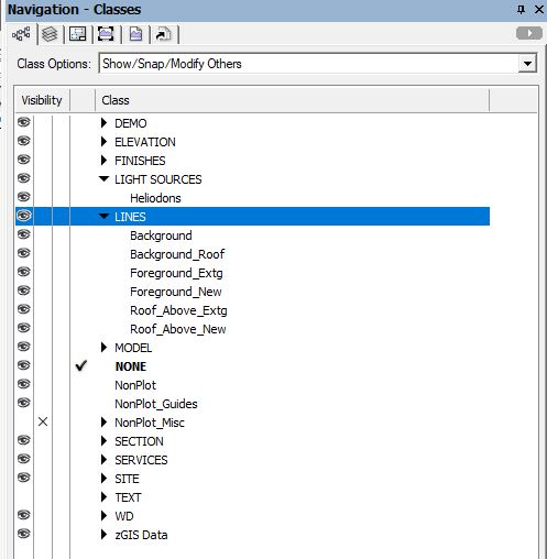
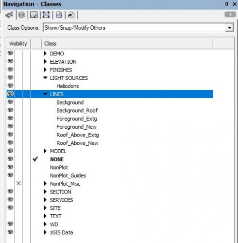
Hey TKA. Yes that is the "hierarchical" display mentioned as attached screenshot: In addition to the viewport class visibilities dialogue it would also be great to see hierarchical display used in the "new class" dialogue. Currently I have to scroll down through dozens and dozens of template file classes to find the one I want to import. This would be a lot quicker if an option to show in hierarchical display was provided. Btw there was a recent post about setting up viewport templates and using the eyedropper tool to transfer visibilities from one viewport to another:
-
I understood it to be about hierarchical display of classes in the class visibilities dialogue of viewport settings.
-
I like this idea!