


Boh
-
Posts
1,704 -
Joined
-
Last visited
Content Type
Profiles
Forums
Events
Articles
Marionette
Store
Posts posted by Boh
-
-
There is no tool for finding duplicated layers that I know of however duplicated design and sheet layers get a "-2" after them by default as they can't have the same name.
-
I'm sure there are a bunch of scripts out there that people could share however I've noticed many contributors to this forum and myself included typically set all attributes "by-class" and have a class structure system built into their files.
This has several benefits including:
-saving time setting object attributes
-standardising drawing appearance throughout a file, between files and between users in the same office.
-"global" editing of all objects on the same class by editing the class attributes
-Enabling effective use of viewport class overrides.
the only downside is that a class system requires some effort up front to set up and typically you need quite a few classes to cover the range of object types you are dealing with.
However if done well class the classes are generally straight forward to manage.
-
Sounds like a bug. Perhaps try deleting the referencing and then recreating it again?
-
The changes should show. Have you updated the referenced file in your other drawing?
-
I'm now trying it on VW2018 and having more success. I.e. managing to export though the initial view was a bottom view. Not sure why that was as I set my preferred initial view before exporting.
Finding the orbit & 1st person navigation controls a bit wierd but maybe it's just because I am still learning. Will report back if still struggling after a bit more experimentation.
Thanks!
-
Hi Sean. Is the space label symbol world or page based? Try "edit symbol" in the resource manager and see. It should be page based so that it stays the same size relative to the size of your page - no matter what scale the DL is set to.
Also a good idea to edit page based symbols at 1:1 scale. TI do so create a DL at 1:1 place a symbol in it then right click "edit symbol". Set your text to your desired font size there.
-
Today I have tried using Web view for the first time on VW2017.
My first attempt the file exported but there was nothing in the web view. just the empty sky etc. And yes I defintily had some 3d geometry in the export.
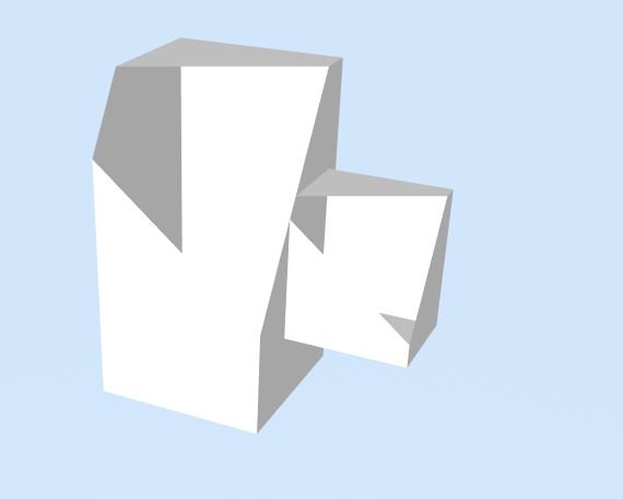
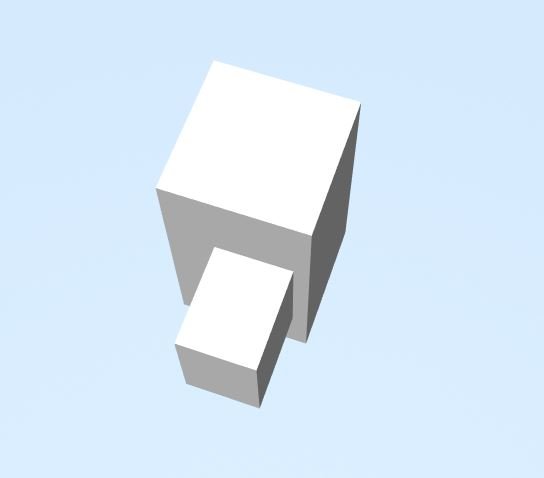
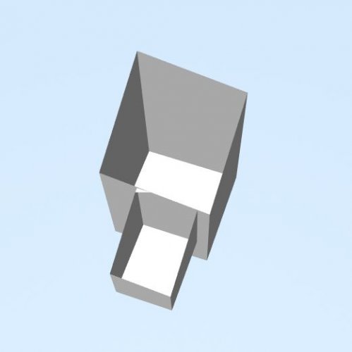
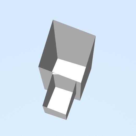
For the secound attempt I created a super simple 3d model - 2 x extrudes and exported that.
This exported but there seems to be a cut in the view depending how close I zoom in. Can some one point me in the right direction with this?
-
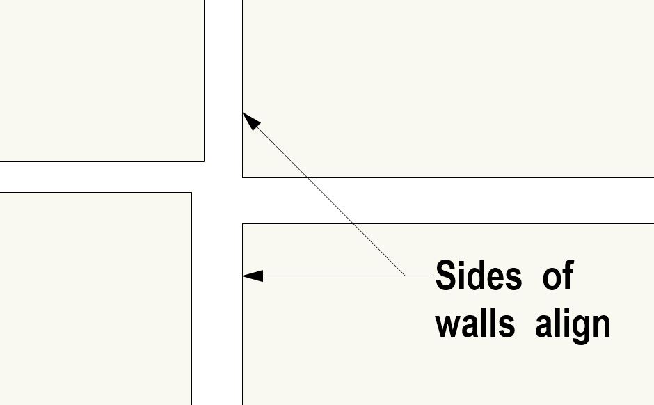
I don't think it is possible to join all 4 walls with the wall join tool as they are currently set out. The walls have to join cleanly onto one wall. Were a wall is "straddling" the ends of two different wall then it is not possible to join it. You could join 3 walls but always have one that won't join.
It looks like the right hand sides of walls 2 & 4 almost align. If you can tweek the set out slightly to align the right hand side of walls 2 & 4 then you can join all walls.

-
All good! Happens to the best of us...
-
Thanks. looks like i already voted!
-
34 minutes ago, klawson said:
You can always add that to your Context Menu in Tools > Edit Workspaces
I couldn't find the "Visibilities..." option under the "all menus" section of the workspace editer. Can you point me in the right direction?
-
Please please fix the stair tool!
-
Please fix the stair tool!
-
 1
1
-
-
I'm not on VW2018 yet but it looks like the stair tool still hasn't been sorted yet... I'm also using the custom stair tool - much more user friendly than the stair tool despite it's many frustrating bugs.
Where do I find the wishlist topic to vote for a stair tool upgrade?
-
I don't know of any specific stacking tools but can you group similarly stacked objects to cut down the number of stacks? For example I typically group room name tags and send them to the front so they stay visible.
another technique is to lock objects objects with solid fills such as slabs or floor finishes that need to be kept at the bottom.
alternatively break up your model into more design layers that can be stacked by reordering them in the Nav palette.
-
Does the wall style have the central component selected as a structural (or perhaps it's called a "core") component? Perhaps check your wall style in the edit wall style dialogue box.
Structural (or "core") components should auto join.
-
I just tried creating a jogged section line on VW2016 and seem to be having the same problem - it only shows the first section on the section line. You can however subsequently still add additional sections and the "jogs" will then show.
Re moving section lines. Yes I wonder how others do this. Moving the section line "sideways" also moves the viewport view the same direction but of course the VP annotations or crop object don't move. Each time I have to go and carefully edit the crop and annotations back to where they should be in relation to the view which is a pain. Does someone out there have a technique to moving section lines that doesn't mess up VP annotations/crops?
-
Typically the existing DTM is generated from the source data inside the DTM. Right click on the DTM and click on edit source data. Add 3d locii or 3d polys to create the terrain on either side of your existing retaining wall.
The proposed DTM is generated from site modifiers placed externally. In that way the proposed modifiers can "overlap" the same terrain as the extg source data.
If you are still confused I could look at your file that you attached but you would have to save it as a VW2017 file for me.
There's been a couple of other threads on site modelling recently you might want to check out too.
-
9 hours ago, line-weight said:
Yes, this works.
In practice though I think I've decided it makes sense to draw things like kerbs as separate objects on top of the surface, because then I have more control over which lines are visible in top/plan view. Because the site model doesn't know to show a line where there's a sharp drop in level like this. Just a step in the contours. I suppose the other option is to draw the line in manually in 2D for top/plan purposes but this won't update automatically if i make changes to the model in the future.
It might be nice if in the source data you could draw certain 3d polygons and specify for them, "draw this edge as a line in top/plan view".
A kerb could be drawn as a 3d polygon and placed on the "site-dtm-modifier" class. It would then be visible as a line in top plan view as well as modify the DTM.
Downside is that it would only be part of the proposed DTM (so would effect cut/fill calcs), also there may be other modifiers on this class that you don't want to be visible.
I usually just end up doing a seperate 2d line for my top/plan view...
-
9 hours ago, line-weight said:
One thing I'm still a bit confused about though... like you say, 3d polylines can only have corner vertices...but I'm sure I've seen somewhere talk of dealing with curved contours and how they are interpolated. And in the "site model" settings there's a setting for "segmentation length" which mentions curved contours:
Is that a VW2018 feature as I can't find it on VW2016 or 2017?
-
23 hours ago, line-weight said:
I've played around a bit with using 3d polylines as edges as you suggest. I wondered if placing two of them, one directly 100mm above the other, would allow me to create a vertical kerb edge but that doesn't seem to work.
No a site model can't have vertical or undercut terrain. If you offset the polys slightly (say a few mm) then you'll get a close approximation of a vertical.
-
On 6 October 2017 at 9:46 AM, Gadzooks said:
Yes Alan, but that doesn't provide the stop end detail required to the upper wall which I assumed RJR was after.
I've done it this way before and edited the wall end detail so it looks just like the desired stop end detail. If you add a couple of vertices to the end of the higher wall you can "notch out" the mitred end.
this technique also works when there is no corner window and you want the walls to look mitred on top plan view.
-
1 hour ago, Benson Shaw said:
@line-weight - More thinking. Two site models can make sense in some of situations. But this practice loses cut/fill information and probably some other features that might be important during design or construction. Perhaps your proposed model can be created as the usual hybrid with most current existing and proposed, but never display the existing from this combo model. Use the other, "existing only" model for vps exclusively associated with the existing status of the site.
How does this way loses cut/fill info? I would suggest having two DTM both created with the exactly the same (existing) source data. The extg site model would have no modifiers applied to it and would just be used for as-existing plans/elevations/sections.
The other would be the proposed site model which would have site modifiers applied and thereby cut/fill calcs are possible. The option to show the "existing & proposed" contours in top/plan view is also available.
As you say though the DTM snapshots does keep a history of changes as well as the opportunity to show the DTM in different styles. I guess they could also good for complex files to just import a snap shot of the DTM held in a seperate file as the DTM's can bulk up a file if complicated.
-
Hmm apologies, I may have confused you in my previous post as I am getting my line naming slightly wrong. I've edited my previous post:
19 hours ago, Boh said:Edit: the "poly"s referred to in below screen shots are 3dpolylines, not polygons!
Edit 2: the "poly"s referred to in below screen shots are 3d polygons, not polygons! (I don't think there is such an object as a 3d polyline...)
So i've done a little research and there are a few types of "polys":
"polygons" are flat polys with only corner vertices. They may not be on the layer plane or horizontal but they will be flat. If you change one of the vertices of a polygon with the reshape tool to any of the other vertice types (fillet/spline/bezier etc) then you will see in the OIP that it has changed from a "polygon" to a "polyline".
A "polyline" can have any of the vertice types but is still flat.
You can convert either polygons or polylines to "3d polygons". Polygons and polylines cannot be used for site model source data but 3d polygons can.
3d polygons do not need to be flat (i.e. their vertices can be moved to any z height) but like 2d polygons they can only have corner vertices. If you convert a rounded polyline to a 3d polygon the rounded portion will be broken down into a bunch of straight segments. 3d polygons viewed in top/plan view have no fill.
Note that a polygon located in 3d space is not a "3d polygon".
On 2/21/2018 at 8:17 AM, line-weight said:To illustrate what I mean about the generated contours not matching the contours I give it, see this screenshot. The line highlighted in orange is a polyline set at 2000, but you can see in the light green generated contours that the 2000 line deviates quite a bit from mine (including at the vertices). On the other hand, where I've placed loci, the generated contours pass through them exactly.
So coming back to your site model issue was the poly in your site model source data an actual "3d polygon" or just a polygon sitting in 3d space? If the former then it should modify your site model.


Help with new workstation
in General Discussion
Posted · Edited by Boh
What sort of issues could we encounter with a Quadro card?
We have just had a new card Quadro P600 card installed into one of our office computers. So far the machine is running VW2016 fine. That said we haven't tried any really large files.
We are also upgrading to VW2018 soon...