Boh
-
Posts
1,704 -
Joined
-
Last visited
Content Type
Profiles
Forums
Events
Articles
Marionette
Store
Everything posted by Boh
-
I had pretty much the same problem a week or two ago and it was my model had geometry to far from the drawing origin. I.e. what @twksaid.
-
Connect points (2D or 3D loci) into lines?
Boh replied to Gilbert Osmond's topic in General Discussion
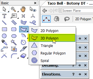
I use the 3d polygon tool:
-
I made some basic try out data sheets for Framing objects and a couple of other things and it is pretty cool how you can filter out what fields you want to see in the OIP data pane and edit the objects from there rather than from the shape pane. It's a bit hit and miss though as it looks like not all types of parametric objects can have data sheets (Title Blocks for example don't appear in the available list of built-in plug-in objects list in the data manager) and not all the settings via the data pane work like their equivalents do in the shape pane or settings dialogues - e.g. to enter a colour in the data pane you need to know the colour number. Mapping data sets by class is pretty slick though. That, I think, will be a useful tool as our office gets better at using records, data tags, worksheets etc. Interesting that mapping a data set to a symbol definition via the data manager doesn't seem to add it to the symbols definition itself rather, from what I seen, adds it to the symbol instances as they are inserted. I.e. after mapping a data set to a symbol definition you can't see the "added" data in the data pane of the RM but when you drag the symbol into the drawing the data is indeed attached to the symbol instance.
-
Symbols issue - Appears to Scale in different files and when active
Boh replied to mta's question in Troubleshooting
Could it be that you are creating page based rather than world based symbols? -
Thanks again @Tom W.. So the tip I picked up going through those posts is to experiment with data sheets. I’m thinking of setting them up to quickly edit commonly changed settings of parametric plugins without having to go into often clunky and overly complicated settings dialogues.
-
Thanks @Tom W.. That was a good tip. I ripped through that course in 15min. The data manager is really powerful but, as the course says itself, is most useful for large collaborative projects using Bim /ifc. We aren’t a big office and whilst we do use ifc the scale of our projects is relatively small so “data management” isn’t really an issue. That said I do like how with the data manager classes can be mapped so that records can automatically be associated to objects placed in classes. How I can use that? I’m not sure... I like to set my object attributes to “by-class” and have a whole range of classes set up specifically to make objects display certain graphic attributes. It seems that data mapping by class could be like an extension of that. The other useful-to-me aspect of the data manager perhaps is the ability to attach records to symbol definitions.
-
@Pat Stanford can you recommend any good tutorials or videos demonstrating how the data manager works? I have looked and can’t seem to find anything for a data noob like myself.
-
Yes or change the dl names in your template. Just as long as the names are not exactly the same. You can just add a dash or full stop to the name. Once imported you can easily move objects from one dl to another. If you’ve done any edits to the dls in your original file like scale, elevation, height etc, you probably want to use those layers rather than the template one anyway.
-
Yes if you duplicate an extg legend you can assign callouts to either one. Do this via the oip. Just to say you will have to be careful with your classing to make sure keynotes are assigned correctly to the same class.as their legend. Slightly risky in my view. Can you put the different phases on different sheets?
- 1 reply
-
- 1
-

-
You classes shouldn’t change. For objects on design layers it is better to import the design layers.. When you import DLs there is an option to import layer objects. Jut make sure the DLS have different names than those already in the file.
-
As I understand it you generally can’t edit geometry via a worksheet, just record info/data. What you can do with a worksheet is see what the x/y coordinates of your labels are and then if you want to adjust any right click on the row header and choose “select item”. This should take you to the item tho I have noticed that with vw 2021 this doesn’t always work with objects in vp annotations. It works if the correct sheet is active when the “select item” is done. So if you have a column in your worksheet for sheet layer then you can see which sheet a label is on and make the sheet active before selecting the item. All that said, like @jeff prince I just manually locate drawing labels. We have a 5x5mm guide grid built into our titleblocks and along with snapping and full screen cursor cross hairs lining things up is pretty quick.
-
All gd. There is an option to enter delta x an delta y instead of an angle. Gd luck.
-
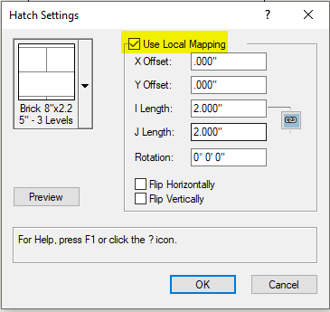
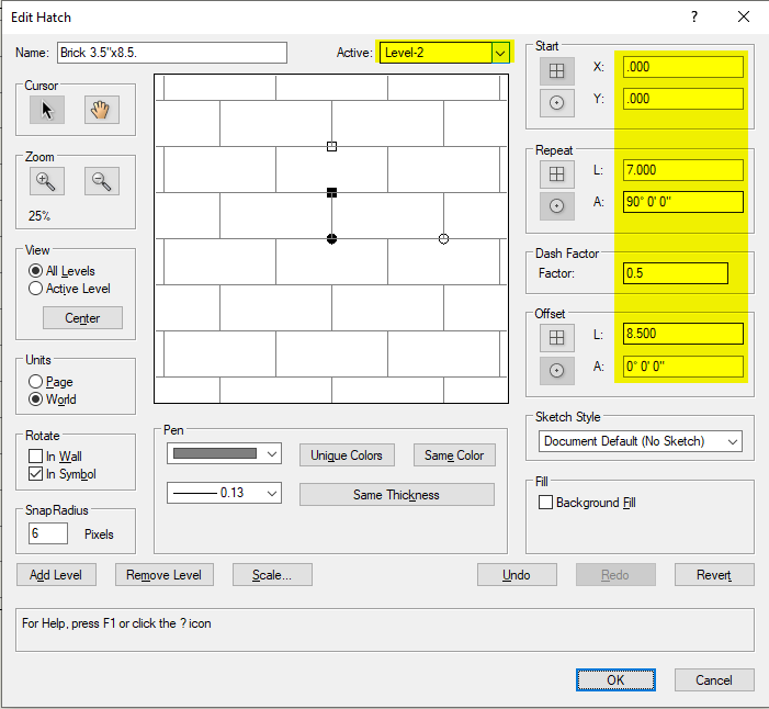
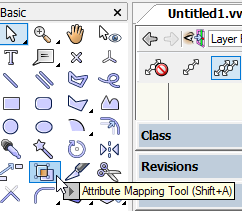
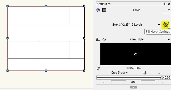
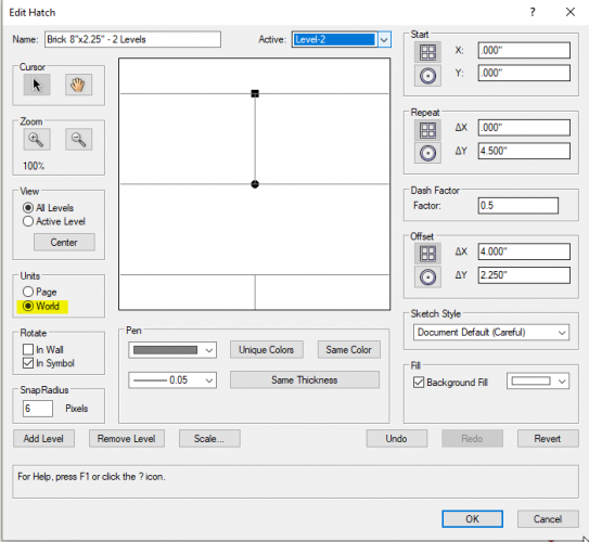
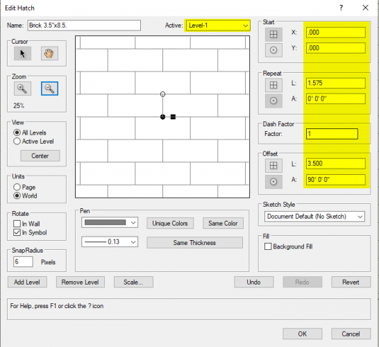
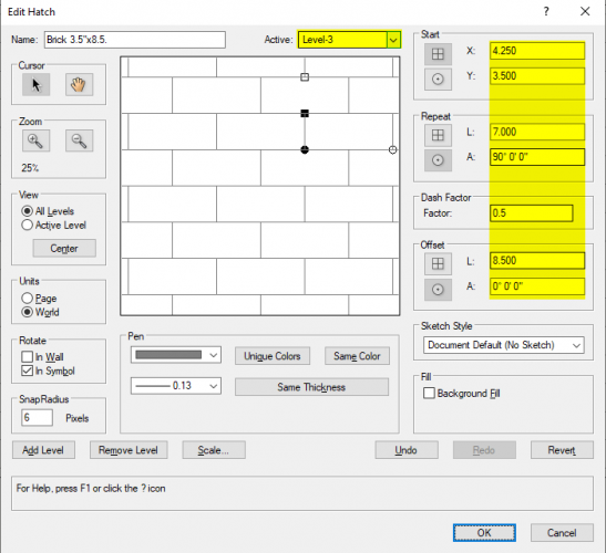
Apologies I've confused you. Firstly - I didn't read your post properly and gave you the hatch settings for the default vw 3.5"x8.5" brick hatch rather than what you wanted, i.e. a 2.25"x8" brick. Secondly - you can do the hatch edit in 2 levels rather than three. 3 level just breaks the vertical running bond coarse lines into 2 different levels which is perhaps easier to understand. 2 levels does the vertical lines in one level. Thirdly - I should have also mentioned to make sure the hatch is world based rather than page based. Here's an explanation of the hatch edit settings for a 2.25"x8" brick for both 3 level and 2 level hatches. 3 Level brick hatch Level 1 - Solid horizontal coarse lines. Repeat: not required as is a solid line (can be set to anything). Offset: The height between horiz lines: i.e. one brick height ΔY=2.25" Level 2 - Dashed vertical lines offset horizontally a full brick along with no vertical offset. Starting point X=0, Y=0. Repeat: You want the vertical lines to repeat vertically every second coarse so ΔY = 2x 2.25=4.5". Dash factor is set to 0.5 so that only half the repeat is solid i.e. one brick coarse solid then one brick coarse gap. Offset: This is just horiz distance between vertical lines with no ΔY offset. i.e. ΔY = 0, ΔX = one brick length = 8". Level 3 - As level 2 but just with different starting point of half a brick length along and one brick high: X = 4", Y = 2.25" Repeat: As level 2. Offset: As level 2. 2 Level brick hatch Level 1 - Solid horizontal coarse lines. Settings as Level 1 for 3 level brick hatch above Level 2 - Dashed vertical lines with horizontal offset half a brick along and one brick high. Starting point X=0, Y=0. Repeat: As Level 2 setting for 3 Level Brick Hatch above (ΔY = 4.5" / dash factor = 0.5). Offset: Here the horiz offset is half a brick along and the vertical offset is one brick high. ΔX = 4", ΔY = 2.25". Hope that makes sense! Now try and allow for the width of the mortar joints in that!! You can locally map a hatch, i.e. change it's scale, alignment and rotation via the attribute mapping tool or via the attributes palette. The attribute mapping tool will only let you scale it proportionally (what I called "direct scale" in previous post). This is where the x axis is scaled the same as the y axis. To go from a 3.5"x8.5" brick to a 2.25"x8" brick you have to scale the x axis differently from the y axis. You can do this via the attributes palette by playing with the local mapping "I length" and "J length" settings but that to me looks even harder than just redoing it in the hatch edit dialogue. The attribute mapping tool is in the basic tool set. Have a play with it, it is really useful. Adjusting hatch attribute mapping via the attributes palette:

-
Ok that's wierd. Glad you got the @Matt Panzer onto it!
-
Referenced files are linked by their file name and their location. So if you change the name or location you lose the link. I suspect at some point you did a save as and renamed the file or changed its location. The reference will still be looking at the original file/location rather than the saved as one.
-
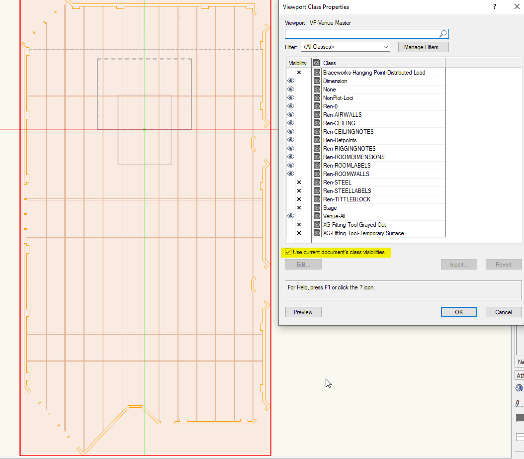
Putting it on another layer will help. Probs need to know what sort of object the white object is but whatever it is putting it on a different class will also allow you to have its visibility switched off in viewports or saved views. I suspect it’s is a polygon that has somehow got “in front” of everything else in the draw order. So you could also try, in a 2d top/plan view , the “send to back” command (ctrl b I think) which should push it “behind” everything else for your 2d view. This won’t effect the 3D view as what is on top is dictated by z values not draw order. If it is a 2d polygon then an alternative to putting the white object on a different layer or class is to put it on the screen plane and then activating unified view with uv settings to not display screen plane objects in. 3D views. This will make it visible in 2d but not visible in 3D. With white object selected, in the object info palette there is a “plane” drop down. It should say “layer”, change this to “screen”. Then in the view menu putting a check mark next to unified view and just below that select the unified view settings. Put a check Mark next to “hide screen objects in 3D views” Hope these suggestions help. Cheers
-
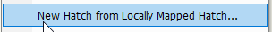
There is a quick way to create a new hatch from an existing one and that is by locally mapping the hatch, either with the Attribute Mapping tool or via the attributes palette, and then right click and hit: Downside is that for your brick you don't want a direct scale of the brick proportions so unless you are adept at locally mapping to what you want then you probably need to go back to the less than intuitive hatch edit dialogue. To make it a bit easier I have edited another brick hatch to be 3.5" x 8.5". There are three layers to a brick hatch. You can copy the settings for each layer from the screen shots below. Cheers


-
Haha unfortunately I’m not a genius. Just someone who happened to have pretty much the exact same issue just last week 😁. It only took me 3 hours to realise there was a toilet symbol pasted into the file 30km from the origin... I saw the rendering issue which made me suspect this was the issue then saw the x/y coordinates of your symbol screen shot. Glad you got it sorted!
-
One of your screen shots showed your dlvp some distance from the origin, which may mean the model in the ref file is also some distance away. Suggest you bring things closer to home then see if the probs are still there.
-
My first thought is have you done a save with the file being referenced and then updated the reference?
-
Hey Bertin. Are you sure the license is current? Maybe you need to go to your college/university and ask them to check? Id also suggest you approach you local tech support. It looks like the solution needs to come either from vectorworks inc or your school IT department.
-
People on this forum are very helpful but as @Tom W.says some more details are required. What sort of object is the “white layer” you mentioned.? If it a 2d polygon then changing it to screen plane with the right unified view settings will allow only the 3D geometry to show in 3D views whilst keeping 2d geometry visible in top/plan views.
-
Not sure. Needs further investigation. There is something about it being in a symbol that came into play. I ran out of time to play further.
-
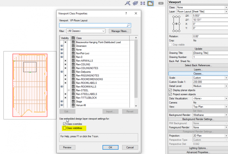
@C. Andrew Dunning I haven't found this to be the case when I opened your file. Mind I don't have vw2020 so opened it with v2021. Have you played with these settings?

-
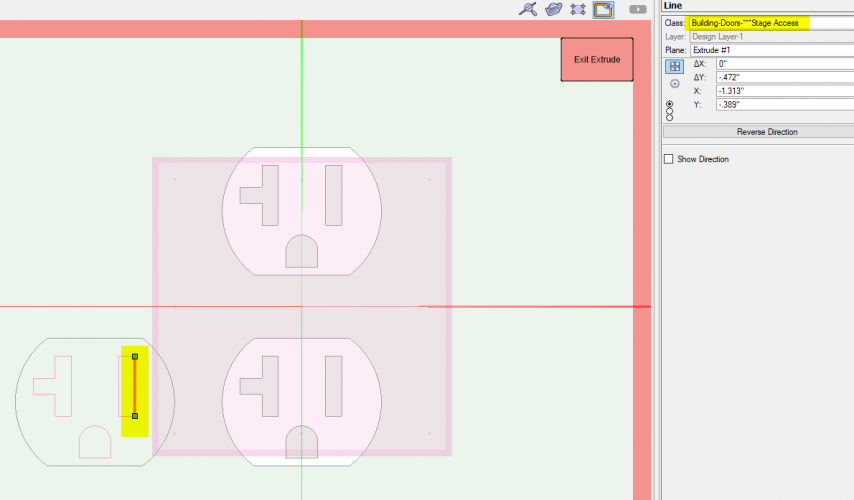
Hey @JB_Tech3 I had a look at your file. This is interesting. It seems that when you decompose the polylines defining one of the extrudes in the 3d component of the "AC Outlet Horizontal", then some of the lines pop up in the Building-Doors-***Stage Access class. However changing these lines to the none class and recomposing the polylines still doesn't allow the Building-Doors-***Stage Access class to be purged from the file. It somehow seems to be stuck to the symbol. No other decomposed geometry in the symbol showed up the Stage Access class. To get rid of the class I had to rebuild the symbol - essentially copying and pasting all the 2d, 3d and wall component geometry into a new symbol definition. Attached is your file with the rebuilt symbol - now called "AC Outlet Horizontal - New". This file doesn't have the Stage access class in it. Phew! So if you import the "New" symbol into your file then delete the old one, replacing all instances of the old with the new as you go, then you should be able to delete the Stage Access class. That's assuming there are no other symbols in your file displaying similar behaviour. Good luck! ClassAssignmentIssue.vwx